Computime TDL6192 US SMART PLUG User Manual
Computime Limited US SMART PLUG
User Manual

US Smart Outlet Purchase Spec September 21, 2012
Doc: D10025-002 Tendril Confidential Page i
US Smart Outlet
Purchase Specification
Revision 1.02
July 17, 2012
Document: D10025-002
Tendril Inc.
2560 55th St
Boulder, CO 80301

US Smart Outlet Purchase Spec September 21, 2012
Doc: D10025-002 Tendril Confidential Page ii
This document contains information that is extremely sensitive to Tendril and its suppliers. It is an
unpublished work that contains confidential and secret information that is protected under the copyright
laws. The existence of the copyright notice is not to be construed as an admission of presumption that
publication has occurred. Restricted Rights: Use, duplication, or disclosure by the U.S. Government are
subject to restrictions as set forth in subparagraph © (1) (ii) of the Rights in Technical Data and Computer
Software clause at DFARS 252.227-7013.
Do not reproduce or further distribute without written consent from Tendril Corporation.
Copyright © Tendril Corporation 2012. All Rights Reserved.
Tendril and the Tendril logo are trademarks of Tendril Corporation, registered in the U.S.A. and other
countries.
Author / Editor
Tim Hughes x2146
Devices Development Group
Location
//Filer/Groups/Engineering/Engineering Specs/US Smart Outlet Purchase Spec D10025-000.doc
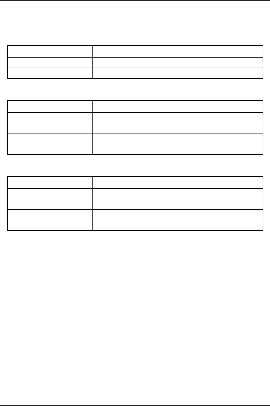
Revision History
Document Name - Doc Number Date Summary
US Smart Outlet Purchase Spec D10025-000.doc 03/22/12 Initial Version
US Smart Outlet Purchase Spec D10025-001.doc 06/28/12 CUL / CSA added
US Smart Outlet Purchase Spec D10025-002.doc 07/17/12 Label Spec Updated

US Smart Outlet Purchase Spec September 21, 2012
Doc: D10025-002 Tendril Confidential Page iii
TABLE OF CONTENTS
1 INTRODUCTION .................................................................................................................................... 1
1.1 Executive Summary...................................................................................................................1
1.2 About This Specification............................................................................................................ 1
1.3 Related Documents................................................................................................................... 1
2 PRODUCT DESCRIPTION .................................................................................................................... 2
2.1 Features..................................................................................................................................... 2
2.2 Electronic Hardware Description ............................................................................................... 2
2.2.1 Block Diagram..................................................................................................................... 3
2.3 Relay.......................................................................................................................................... 3
3 Performance Specifications ................................................................................................................ 4
3.1 Reliability ................................................................................................................................... 4
3.1.1 Reliability Testing................................................................................................................ 4
3.2 Power......................................................................................................................................... 4
3.2.1 Power Source...................................................................................................................... 4
3.2.2 Power Consumption............................................................................................................ 4
3.2.3 Noise Rejection................................................................................................................... 4
3.2.4 Power Cycling ..................................................................................................................... 4
3.3 Sub-metering Accuracy ............................................................................................................. 5
3.4 Radio ......................................................................................................................................... 5
3.4.1 HAN Radio Specifications................................................................................................... 5
3.4.2 Channel Tx Power............................................................................................................... 5
4 Physical Specifications........................................................................................................................6
4.1 Dimensions................................................................................................................................ 6
4.2 Appearance ............................................................................................................................... 6
4.3 LEDs.......................................................................................................................................... 6
4.4 Button ........................................................................................................................................ 7
4.5 Device Labeling ......................................................................................................................... 7
4.5.1 Housing and Agency Label................................................................................................. 7
4.5.1.1 Company and Product Name ................................................................................... 7
4.5.1.2 Tendril Logo.............................................................................................................. 7
4.5.1.3 Model Number.......................................................................................................... 7
4.5.1.4 Label Example.......................................................................................................... 7
4.6 ESD Failure Level Limits ........................................................................................................... 8
4.7 Environmental Specifications ....................................................................................................9
4.7.1 Altitude ................................................................................................................................ 9
4.7.2 Temperature........................................................................................................................ 9
4.7.3 Humidity .............................................................................................................................. 9
4.7.4 Actual Environmental Test Corners .................................................................................... 9
4.8 Shock and Vibration Specifications......................................................................................... 10
4.8.1 Transportation Vibration.................................................................................................... 10
4.8.2 Transportation Drop .......................................................................................................... 10
4.8.3 Non-Operational Shock..................................................................................................... 10
4.8.4 Non-Operational Vibration ................................................................................................ 11
4.8.5 Operational Random Vibration..........................................................................................11
5 Installation...........................................................................................................................................12
5.1 Location ................................................................................................................................... 12
5.2 Maintenance / Service............................................................................................................. 12

US Smart Outlet Purchase Spec September 21, 2012
Doc: D10025-002 Tendril Confidential Page iv
6 Manufacturing / Test Specifications.................................................................................................12
6.1 Manufacturing Process............................................................................................................ 12
6.2 Minimum Testing Requirements..............................................................................................12
7 Agency Requirements........................................................................................................................13
7.1 Electromagnetic Compatibility (EMC)...................................................................................... 13
7.1.1 Background Radiation.......................................................................................................13
7.1.2 RF - United States - FCC.................................................................................................. 13
7.1.3 RF - Canada - IC...............................................................................................................13
7.2 Safety....................................................................................................................................... 13
7.2.1 Safety Standards...............................................................................................................13
7.2.2 Required Safety Notifications............................................................................................ 13
7.2.3 Additional UL Requirements .............................................................................................13
7.2.4 Future Agency Certification Plans..................................................................................... 13
7.3 Environmental Impact.............................................................................................................. 14

US Smart Outlet Purchase Spec September 21, 2012
Doc: D10025-002 Tendril Confidential Page 1
1 INTRODUCTION
1.1 Executive Summary
The US Smart Outlet is a radio controlled outlet that can apply or remove power to a device plugged into
its receptacle. It also measures RMS power being utilized by the device being controlled.
The Outlet communicates wirelessly via 802.15.4 ZigBee SE 1.0 protocol, and responds to the ZigBee
Smart Energy commands. It can be controlled via the Tendril Connect Platform through several portals
(consumer, utility, support) for use in home automation and energy monitoring applications. The device is
intended for indoor applications on UL rated 15A circuits.
1.2 About This Specification
This document describes the Outlet minimal requirements for purchase, such as performance,
environmental specifications, and regulatory compliance requirements. This document is created and
maintained by the Engineering and Operations Team.
1.3 Related Documents
• D10009-1xx Outlet Engineering Specification
• D10080-0xx Outlet Test Specification
• D10022-XXX Product Labeling Spec
• D10079-XXX Tendril Supplier Quality Policy

US Smart Outlet Purchase Spec September 21, 2012
Doc: D10025-002 Tendril Confidential Page 2
2 PRODUCT DESCRIPTION
2.1 Features
1) Smart Energy (SEP 1.1) certified via NTS or similar test house
a) AES 128 bit encryption across the HAN
b) Multiple ESI Support
c) Cluster Binding
d) ECC capability with Production Certificates
2) Switches 120V, 15A UL rated device on or off via SEP DR Clusters and Tendril custom control
commands. Device uses a latching SP relay that opens the hot side..
3) Application Bootloader OTA upgrade capability of radio FW.
4) Current, Voltage, and power measurement of attached loads, made available via the SEP Simple
Metering Cluster
a) ID = Instantaneous Demand = Power (V*I*PF)
b) CSD = Current Summation Delivered = Energy (kWh)
c) Voltage = Special Tendril Cluster
d) Current = Special Tendril Cluster
5) Certifications
a) UL 916 (Load Management Equipment)
b) Canadian UL Listed to Canadian Safety Standards (CAN/CSA 22.2)
c) FCC 15-B approval (US)
d) FCC ID and IC numbers on labels
e) Other International Certifications planned for future versions
1) Consumer safe, durable plastic housing for indoor use
2) Push Button for:
a) Opt out of DR events or other OFF condition
b) Scanning for networks for non-ECC HANs
3) Colored LEDs indicate status
2.2 Electronic Hardware Description
PCBs contains:
• ZigBee Radio Module containing:
o EM357 Radio SoC
o 100mW RF Power Amp operating at 2.4GHz
o 1MB external serial flash EEPROM
• 5V and 3.3V regulation
• Bi-color LED
• Switch for button
• Internal UART and test port connections sufficient to access the processor for programming at
initial manufacture, and validate PCBA functionality
• 150VAC / 16A minimum rated latching relay with 5V coil
• Current and voltage monitoring circuitry for the connected load
Further power and radio specifications are listed in the Performance Section below.
US Smart Outlet Purchase Spec September 21, 2012
Doc: D10025-002 Tendril Confidential Page 3
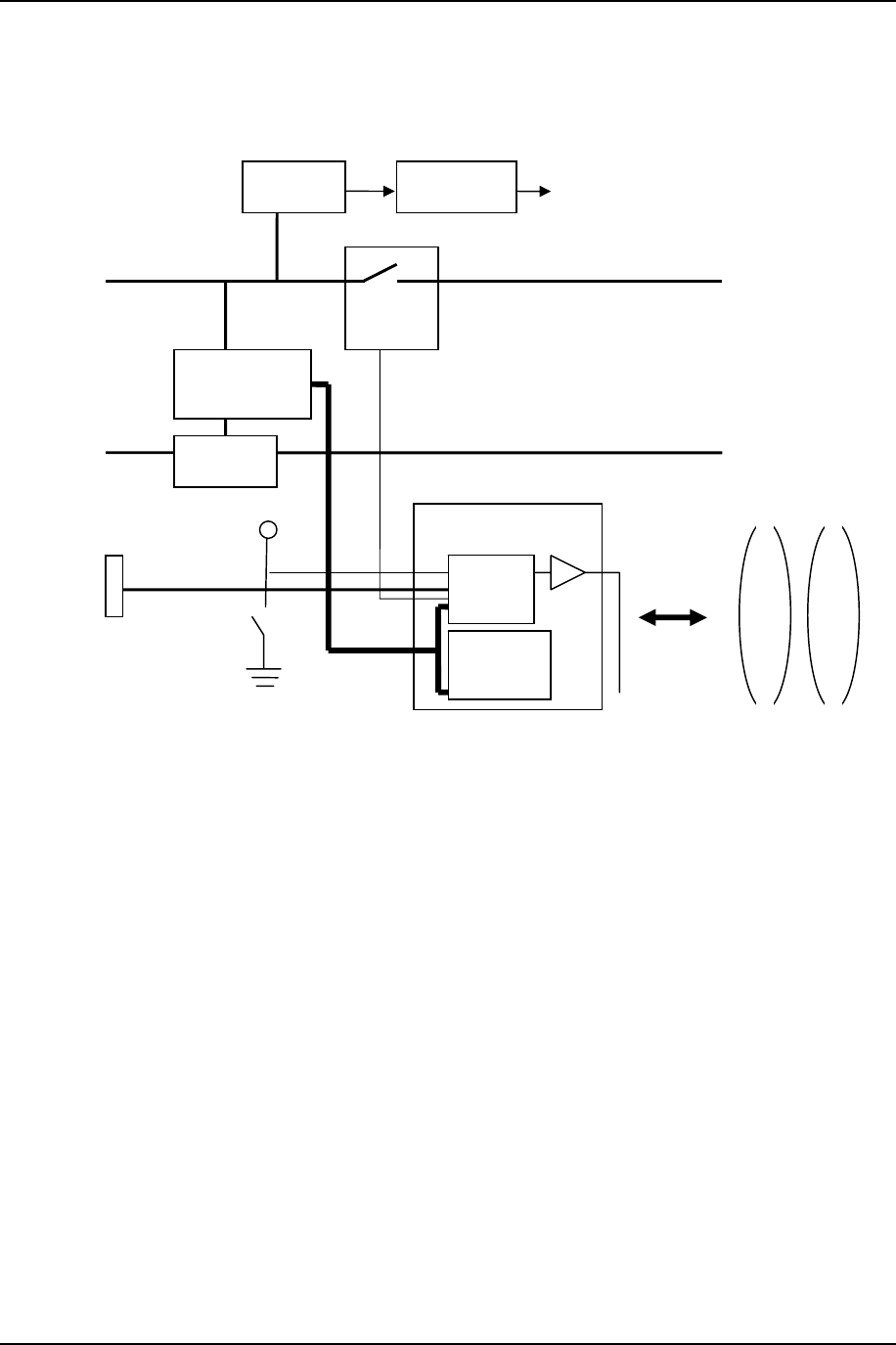
2.2.1 Block Diagram
2.3 Relay
The device uses a latching relay, to retain the state through a device reset following an OTA. If a
standard Normally Closed relay is used, and the device is reset while the relay is open, it will close
momentarily. This is avoided if the relay is latched, and reset will not affect it.
ZigBee RF Module
RF to/from
HAN
Relay
Button
3.3 V
5.0 V
PCB
Trace
Antenna
Linear
Reg
LED
AC In
Hot
AC In
Neutral AC Out
Neutral
AC Out
Hot
V + I
Measurement
Current
Sense
Switching
Reg
Test /Program
Header
Serial
Flash
EEPROM
Ember
357

US Smart Outlet Purchase Spec September 21, 2012
Doc: D10025-002 Tendril Confidential Page 4
3 Performance Specifications
3.1 Reliability
MCBF Environment
Unit reliability = 500,000 POH (based on component analysis)
Equates to a failure rate of 1.7% per year over the useful service life of 5
years.
Indoor Residential
Switching reliability = 100,000 MCBF operating both relays at 10 A resistive
load Indoor Residential
3.1.1 Reliability Testing
The reliability specification is tested at 120 VAC, 10A load while maintaining ZigBee radio communication.
• The radio shall not reset during device switches.
• ZigBee communication shall not be degraded by a consumer noticeable level during normal
operation.
3.2 Power
3.2.1 Power Source
The unit is powered from a standard US 120 VAC + 10% source @ 50-60Hz. The unit operates over an
input range of 100 to 150 VAC.
3.2.2 Power Consumption
AC Power Consumption is 0.6 W in quiescent state, ranging up to 1.5 W during RF transmission and all
LEDs illuminated. 50ms surges of up to 0.5W additional power draw can occur when relay state changes
are activated.
3.2.3 Noise Rejection
The unit meets ANSI C37.90a Surge Withstand Capability and other immunity requirements as specified
in the agency requirements in Section 7.
Furthermore, no permanent damage to the unit will occur if noise on the AC power line is below the
following specifications:
• Motor noise spikes of an extra 30V peak on top of the nominal AC line voltage and frequency
3.2.4 Power Cycling
The unit shall perform without failure through 3600 power cycles. This is based on a use case of 2 power
cycles/day over 5 years.
Testing to validate this spec is done by cycling power for 5 seconds on, 30 seconds off, repeated 7200
cycles on a population of 4 units. This provides ~80% confidence this spec is met.
US Smart Outlet Purchase Spec September 21, 2012
Doc: D10025-002 Tendril Confidential Page 5
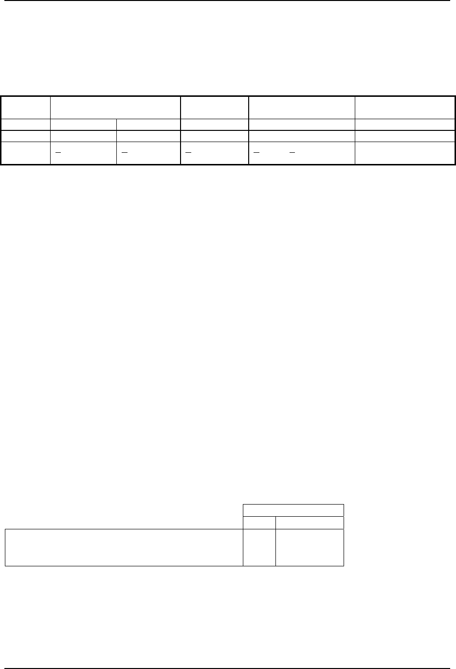
3.3 Sub-metering Accuracy
The unit measures and reports Voltage, Current, Instantaneous Power, and Energy as described in
Section 2.1. Note that only Power and Energy are presently reported to TNOP. The accuracy is
specified as follows:
CurrentRMS VoltageRMS Instantaneous
Demand
Current Summation
Delivered
Low Normal
Range 0-1.7 ARMS 1.7-15 ARMS 100-150 VRMS 0.1 -3.0 kW [0, 281 TWhr)
Average
Accuracy + 50 mARMS + 3%
+ 2% + 4% or + 6 W Same as Inst
Demand in %
The current shunt sense accuracy is stated as 3% or 50mA, whichever is higher. Similarly, Instantaneous
Demand accuracy is either 4% or 6W, whichever is larger. Finally, the same % error determined for
Instantaneous Demand carries forward into Current Summation Delivered.
Distortion of the voltage or current can adversely affect the accuracies declared above. Typically this is
not an issue for line powered devices without an SCR or other switching components.
Tendril does not have the equipment or procedure to calibrate units.
3.4 Radio
3.4.1 HAN Radio Specifications
The product conforms to the Zigbee (IEEE 802.15.4 RF) specification and utilizes the ZigBee Smart
Energy profile with additional Tendril functionality. The unit utilizes a fully tested and certified transceiver
module with the following specifications:
• Indoor Range: 300 ft
• Outdoor Line of Sight: 1000 ft
• Tx Power: +20dBm (100mW)
• Rx Sensitivity: -102 dBm
• RF Data Rate: 250 kbps
3.4.2 Channel Tx Power
In order to comply with US FCC Requirements as stated in OET Bulletin No 63, October 1993, the upper
channels are attenuated relative to other channels as follows:
Typical Tx Power
Level Power (dBm)
Channel 11 (2405 MHz) – Channel 23 (2465 MHz) 3 20
Channel 25 (2475 MHz) -3 14
Channel 26 (2480 MHz) -14 4
US Smart Outlet Purchase Spec September 21, 2012
Doc: D10025-002 Tendril Confidential Page 6
4 Physical Specifications
4.1 Dimensions
Specification Value (to be updated)
Length 108 mm (4.5 in)
Width 64 mm (2.75 in)
Depth 35 mm (1.5 in)
Unit Weight 0.22 kg (.5 lbs)
Shipping Weight (packaged) 0.33 kg (.8 lbs)
Packaging Dimensions 228.6 mm (9.0 in) x 177.8 mm (7.0 in) x 69.9 mm (2.75 in)
Orientation Operates in any orientation
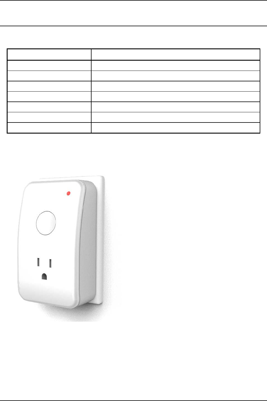
4.2 Appearance
The unit appears roughly as shown.
4.3 LEDs
The unit contains 1 bicolor LED.
US Smart Outlet Purchase Spec September 21, 2012
Doc: D10025-002 Tendril Confidential Page 7
4.4 Button
A large button on the front of the unit is used to provide manual input to the processor. It provides tactile
feedback upon closing the switch. It activates with < 1lb pressure and is warranted for 5000 presses.
4.5 Device Labeling
Please refer to the Product Labeling Specification D10022-001 for the general device labeling
requirements. This section covers device specific details over and above that specification.
4.5.1 Housing and Agency Label
For this product, the Housing and Agency labels can be split into two labels or applied as one label (on
the back of the unit) as long as clear readability of the contents are maintained. EUI-64, Installation Code,
Agency marks, FCC ID and IC numbers must be clearly visible.
4.5.1.1 Company and Product Name
This product should display manufacturer’s company and model name on the label instead of
“Tendril Networks, Inc.” specified in the Product Labeling Spec.
4.5.1.2 Tendril Logo
Instead of Tendril Logo specified in Product Labeling Spec, the following logo should be placed on
any one of labels.
This logo identifies the product as Tendril Connect certified.
4.5.1.3 Model Number
Tendril model number for this product is defined as TDL6192
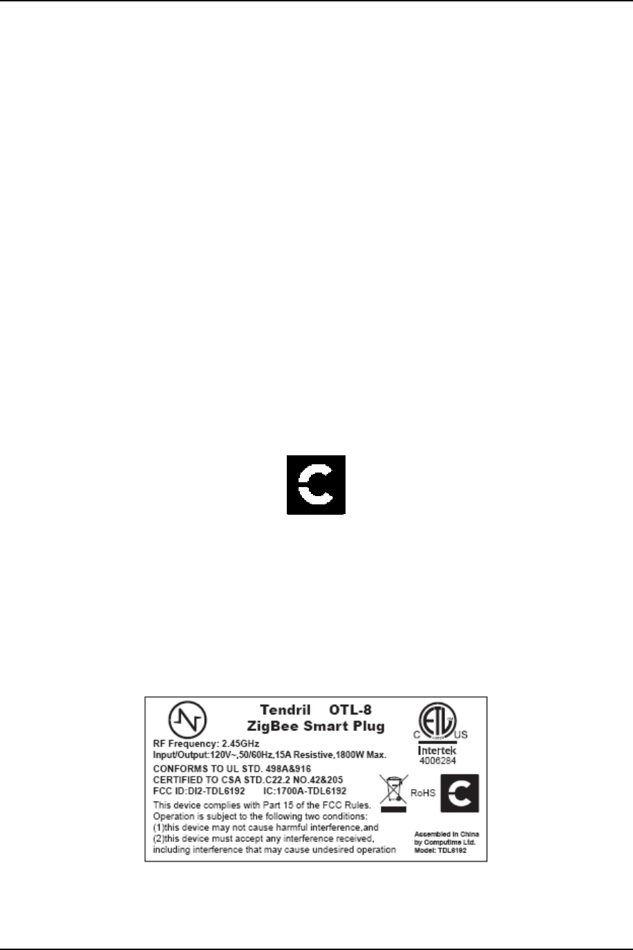
4.5.1.4 Label Example
Below is a sample of contents in a single label case. Please refer to the Product Labeling Spec for
two labels.

US Smart Outlet Purchase Spec September 21, 2012
Doc: D10025-002 Tendril Confidential Page 8
4.6 ESD Failure Level Limits
Failure Type Equipment Failure Level Allowable Errors
Hardware Office 1 to 8 kV No operator intervention
(recoverable error allowed)
Hardware Office Up to 15 kV No component damage - operator intervention
allowed
The unit is tested in its normal usage state, plugged into a grounded wall outlet.
Ref Document: 89/336/EEC, Directive Concerning Electromagnetic Compatibility (EMC)
Test Specification: EN61000-4-2. Refer to Section 7 for further immunity specifications.
ESD protection and warranty are voided if the unit is opened by personnel other than Tendril or the
supplier employees.
US Smart Outlet Purchase Spec September 21, 2012
Doc: D10025-002 Tendril Confidential Page 9
4.7 Environmental Specifications
4.7.1 Altitude
Altitude Value
Operating Range -500 feet to 15,000 feet
Non-operating Range -500 feet to 50,000 feet
4.7.2 Temperature
Temperature Value
Operating Range 0o C to 40o C
Operating Gradient Maximum of 15o C per 60 minutes
Nonoperating Range -40o C to 65o C
Nonoperating Gradient Maximum of 20o C per 60 minutes
4.7.3 Humidity
Humidity Value
Operating Range 10% to 90% (non-condensing)
Operating Gradient Maximum of 20% per 60 minutes
Nonoperating Range 5% to 95% (non condensing)
Nonoperating Gradient Maximum of 20% per 60 minutes
4.7.4 Actual Environmental Test Corners
Operational
0°C @ low absolute humidity
0°C @ 90%RH
40°C @ 20%RH
40°C @ 70%RH
32°C @ 90%RH
Non-operational Storage
+20°C at 10% RH
+65°C at 5% RH
+32°C at 95% RH
+20°C at 20%
-40°C
US Smart Outlet Purchase Spec September 21, 2012
Doc: D10025-002 Tendril Confidential Page 10
4.8 Shock and Vibration Specifications
4.8.1 Transportation Vibration
This test exposes the unit under test, packed for shipment to transportation vibration for approximately
one hour.
• The test shall be done to the same units under test, using the same packaging, as the units used
for Transportation Drop Test and shall be conducted PRIOR TO the Transportation Drop Test.
The units under test, packaged in their intended packaging shall meet the requirements identified
in Vibration Testing in the International Safe Transit Test Procedure 1A.
4.8.2 Transportation Drop
This test shall follow Transportation Vibration and shall be conducted as described in Shock Testing in
the International Safe Transit Association test procedure 1A.
• The device shall be in its intended final packaging.
• The device shall be exposed to ten drops to hard floor in accordance with the above referenced
International Safe Transit Association standard.
4.8.3 Non-Operational Shock
The product shall pass a test conducted as described in ICE 60068-2-27 REV 1987 based on the
following conditions:
1. The device shall not be operating and shall be without packaging.
2. The device shall be rigidly mounted to a test fixture and at a reference point for the control
accelerometer shall be attached to the test fixture.
3. Half sine pulse applied 3 times in each direction, for each of the 3 mutually perpendicular axes
and a total of 18 shocks.
4. Peak acceleration shall be 15 g (150 m/s^2) with a duration of 11 ms with a corresponding
velocity change of 1.0 m/s.
5. Post test, an accuracy performance check shall be performed to verify function.
Specification Value
Pulse Shape Half sine wave
Peak Acceleration 15 G (150 m/s^2)
Duration 11 ms
Application 3 pulses per side for 3 sides
US Smart Outlet Purchase Spec September 21, 2012
Doc: D10025-002 Tendril Confidential Page 11
4.8.4 Non-Operational Vibration
The product shall pass a test conducted as described in ICE 60068-2-6 REV 1987 based on the following
conditions:
1. The device shall not be operating and shall be without packaging.
2. The device shall be rigidly mounted to a test fixture and at reference point for the control
accelerometer that shall be attached to the test fixture.
3. The test shall be run over a frequency range of 30 to 350 Hz with a sweep time of one octave per
minute at 5 m/s^2 (0.5 g) along each of three mutually perpendicular axes.
4. The sweep duration shall be 30 minutes also each axis.
5. Post test an accuracy performance check shall be performed to verify function.
Specification Value
Frequency Range 30 - 350 Hz, sweep of one octave/minute
Acceleration Level 0.5 G (5 m/s2) along each axis
Application 1.5 hour total test time. 30 minutes along each axis
4.8.5 Operational Random Vibration
The product shall pass a test conducted as described below based on the following conditions:
1. The device shall be operating and shall be without packaging
2. The device shall be rigidly mounted to a test fixture and at a reference point for the control
accelerometer that shall be attached to the test fixture
3. The test shall be run over a frequency range of vibration as described below.
4. Concurrent with vibration and post test, an accuracy of performance check shall be performed to
verify function.
Random Vibration
Specification Value
Frequency Range 1-400 Hz
Acceleration Level 1.06 Grms
Application 3 sides - 20 minutes per side
PSD Spectrum
Frequency PSD (g2/Hz)
1 Hz 0.0003
3 Hz 0.0055
12-100 Hz 0.01
400 Hz 0.000003

US Smart Outlet Purchase Spec September 21, 2012
Doc: D10025-002 Tendril Confidential Page 12
5 Installation
5.1 Location
The unit is designed for indoor use, plugged into a standard wall outlet, covering both receptacles, or into
an appropriately grounded extension cord. The package is designed for In-home installation. The
product is not intended to operate exposed to the elements.
5.2 Maintenance / Service
The device requires no user maintenance. Users should observe the requirement that the electronics
within the device be kept enclosed and sheltered from the elements. The firmware within the device will
be maintained via the Tendril OTA or SE1.1 OTA process.
The device is not user serviceable. Units that are defective or not repairable via the OTA process require
an RMA process. Details on the RMA process are found in the Master Supply Agreement.
6 Manufacturing / Test Specifications
6.1 Manufacturing Process
The units are manufactured at a UL certified facility that has been approved by Tendril. Refer to D10079-
XXX Tendril Supplier Quality Policy for supplier requirements.
EC approval is specified in the Long Form Agreement.
A database containing the following items per device is maintained and available to Tendril:
1. Serial Number
2. EUI-64
3. Installation Code
4. ECC Certificate (or a cross reference to a secure list)
5. Manufacture Date
6. Pass/Fail results for the parameters listed below, with parametrics as available
6.2 Minimum Testing Requirements
The Manufacturing Test Requirements document shall e provided by the supplier and approved by
Tendril. That That testing may be a superset of this minimal requirement list stated here:
1. Program the radio processor and validate success
2. Validate 2 way RF communication
3. Verify both relays open and close when commanded by processor
4. Validate metering capability of both channels
5. Validate button and LEDs operate correctly via processor
6. Validate ECC Certificate and any configuration tokens are set

US Smart Outlet Purchase Spec September 21, 2012
Doc: D10025-002 Tendril Confidential Page 13
7 Agency Requirements
7.1 Electromagnetic Compatibility (EMC)
7.1.1 Background Radiation
The unit is certified as passing EMC requirements covered under the UL 916 spec.
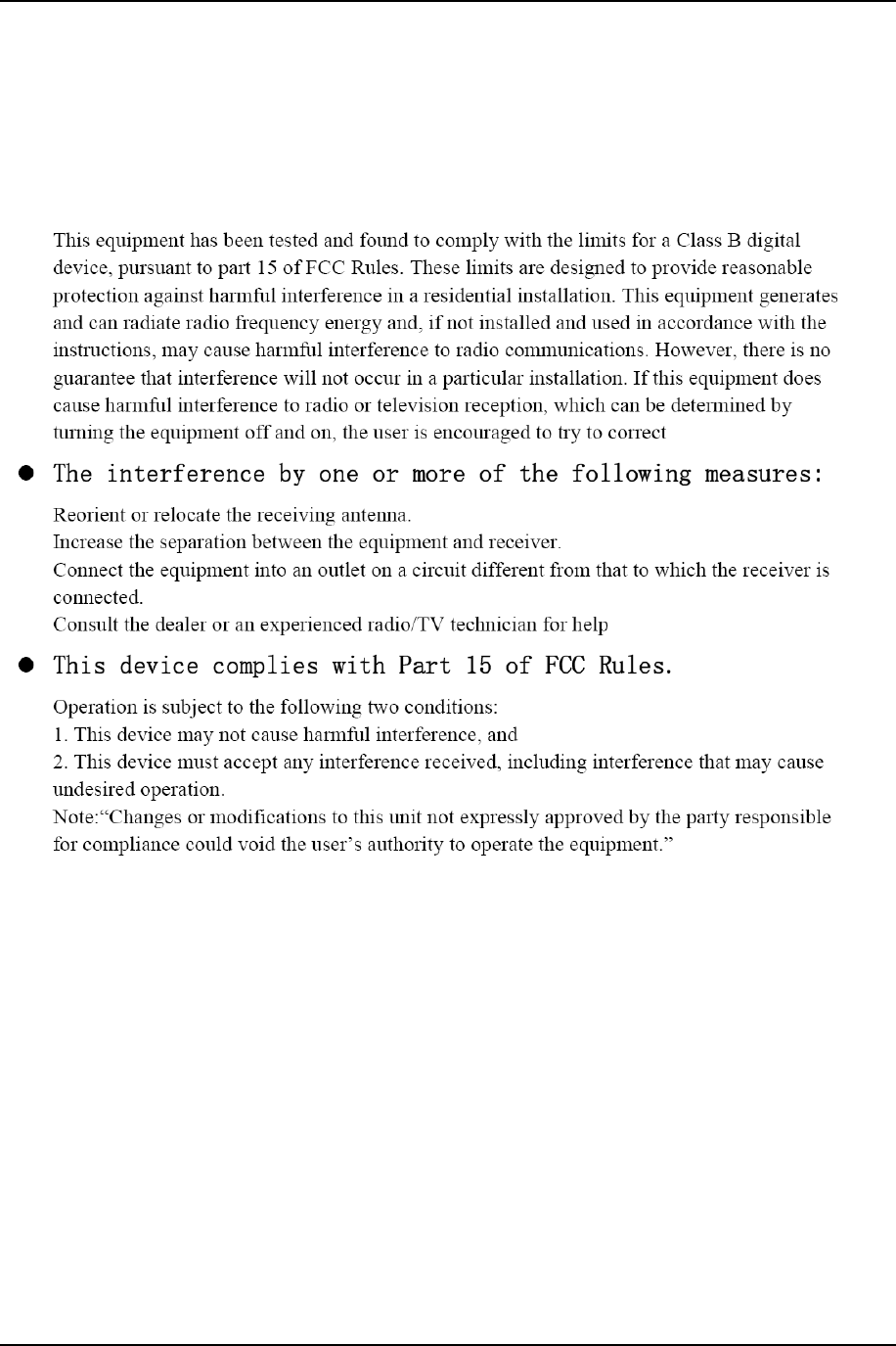
The unit is certified under FCC part 15 Class B. External labeling shall indicate certification.
7.1.2 RF - United States - FCC
The unit meets FCC Part 15 Subpart C for intentional radiators. The radio module FCC ID of QPU3020
extends to device. External labeling shall indicate certification.
7.1.3 RF - Canada - IC
The radio module used internally is IC Certified. The radio module IC: 4523A-SN2030 extends to device.
External labeling shall indicate certification.
7.2 Safety
7.2.1 Safety Standards
The unit displays certification to the following specifications:
• UL 498 and UL 916 (Load Management Equipment) or ETL equivalent
• CAN/CSA 22.2: Canadian UL Listed to Canadian Safety Standards
7.2.2 Required Safety Notifications
Labeling - The label on the units need to be made of a UL or ETL Recognized material by a UL or ETL
Recognized label manufacturer and be suitable for the surface on which it is placed. The label must
contain the following minimal information:
• Manufacturer's name
• Electrical ratings
• Model number
7.2.3 Additional UL Requirements
• All components are UL Certified
• A/C adapters are UL Listed, Class 2, UL flammability rating of the plastics as low as 94 HB
• PCBs are made of a UL Recognized material and manufactured by a UL Recognized supplier
• PCB temperature rating is rated 105 degrees C minimum
7.2.4 Future Agency Certification Plans
As the device is modified to be suitable for international shipment, the following agency certifications will
be required and displayed via labeling:
a) CE (Europe)
b) C-TICK (Australia and New Zealand)
US Smart Outlet Purchase Spec September 21, 2012
Doc: D10025-002 Tendril Confidential Page 14
7.3 Environmental Impact
Meets Waste Electrical and Electronic Equipment Directive (WEEE Directive)
Meets Restriction of Hazardous Substances Directive (RoHS Compliant)
7.4 :Canada/FCCStatement