Comtech Mobile Datacom CMDCMTM203 L Band Satellite Earth Station User Manual
Comtech Mobile Datacom L Band Satellite Earth Station
User Manual

Comtech Messaging System (CMS)
MTM-203 Transceiver Module
End User Manual
Document Version: B
Document Number: CMDC-DOC-0138
Author: Kerry Keksz
Date: November 1, 2006
Privilege Level: Customer
Transceiver Host Firmware: 3.4T
Transceiver DSP Firmware: Altera 0.227
This document is property of Comtech Mobile Datacom, Germantown, Maryland.
This document is not to be disclosed to persons outside the organization without written authorization and execution of
a Non-Disclosure Agreement. ©2006 Comtech Mobile Datacom Corporation.
Comtech Mobile Datacom Corporation (hereafter referred to as ‘Comtech’) is a subsidiary of Comtech
Telecommunications Corporation.
This document contains confidential business or system information. Any possession, use, or copying of this material
requires prior written permission from Comtech.
Comtech shall not be liable for technical or editorial errors or omissions contained herein. The information in this
document is provided “as is” without warranty of any kind and is subject to change without notice. The warranties for
Comtech products are set forth in the express limited warranty statements accompanying such products. Nothing
herein should be construed as constituting an additional warranty.
Product names mentioned herein may be trademarks of their respective companies.
Product is Patent Pending.

Comtech Mobile Datacom Corporation CMDC-DOC-0138, Rev. B
© COMTECH MOBILE DATACOM CORPORATION Page 2 of 37
PROPRIETARY & CONFIDENTIAL
This is an unpublished work protected under the Copyright laws.
All rights reserved.
REVISION HISTORY
Revision Date Revision By Whom Description of the Changes
11/1/06 B Lajuana
Johnson Modified page 34 the Regulatory
Compliance section of the document to
include regulatory information as
required by the FCC.

Comtech Mobile Datacom Corporation CMDC-DOC-0138, Rev. B
© COMTECH MOBILE DATACOM CORPORATION Page 3 of 37
PROPRIETARY & CONFIDENTIAL
This is an unpublished work protected under the Copyright laws.
All rights reserved.
Notices
Throughout this manual, a user will see: WARNINGS, CAUTIONS, NOTES, and
TIPS.
WARNINGS are for procedures that, if not followed, may result in personal
injury or death.
CAUTIONS are for procedures that, if not followed, may result in hardware
or software damage or failure.
NOTES are included to provide the operator with additional information
intended to simplify a step or entire procedure.
TIPS are included for the operator detailing useful information about using
the equipment and software.

Comtech Mobile Datacom Corporation CMDC-DOC-0138, Rev. B
© COMTECH MOBILE DATACOM CORPORATION Page 4 of 37
PROPRIETARY & CONFIDENTIAL
This is an unpublished work protected under the Copyright laws.
All rights reserved.
Safety steps to follow if someone is the victim of electrical shock
1. Do not try to pull or grab the individual.
2. If possible, turn off the electrical power.
3. If you cannot turn off the electrical power, pull, push or lift the person
to safety using a dry wooden pole, or dry rope or some other insulated
material, send for help as soon as possible.
4. After the injured person is free of contact with the source of electrical
shock, move the person a short distance away and immediately render
first aid, as applicable.
WARNING: If nuclear, biological, or chemical (NBC) exposure is
suspected, all air filter media will be handled by personnel wearing full NBC
protective equipment.

Comtech Mobile Datacom Corporation CMDC-DOC-0138, Rev. B
© COMTECH MOBILE DATACOM CORPORATION Page 5 of 37
PROPRIETARY & CONFIDENTIAL
This is an unpublished work protected under the Copyright laws.
All rights reserved.
Table of Contents
1. About this Manual ..............................................................................................7
1.1. Purpose of this Section..................................................................................................7
1.2. Intent of this Document.................................................................................................7
1.3. Terminology Clarification.............................................................................................7
1.4. Conventions Used in this Document.............................................................................7
1.5. Description of Document Contents...............................................................................7
2. Introduction to the Comtech Network..............................................................9
2.1. Purpose of this Section..................................................................................................9
2.2. Components of the Network .........................................................................................9
2.3. Agent...........................................................................................................................10
2.4. Transceiver..................................................................................................................11
2.4.1. Transceiver Subsystems.........................................................................12
2.4.2. High Power Amplifier (HPA) Subsystem...............................................12
2.4.3. Modulator Subsystem ............................................................................12
2.4.4. Synthesizer Subsystem ...........................................................................12
2.4.5. Baseband Subsystem..............................................................................12
2.4.6. Low Noise Amplifier (LNA) and R/F I/O Mux Subsystem .....................12
2.4.7. Down Conversion and A/D Subsystem ..................................................13
2.5. Transceiver Operational Considerations.....................................................................13
2.6. Client API and Command Set (Agent and Transceiver).............................................13
3. Integrating the MTM-203 into a Device .........................................................15
3.1. Purpose of this Section................................................................................................15
3.2. Needed Materials for Integration ................................................................................15
3.2.1. MTM-203 Interface Requirement ..........................................................15
3.2.2. External Power Supply Requirements ...................................................16
3.2.3. External GPS Requirements..................................................................16
3.3. Physical Interface Description ....................................................................................16
3.4. Mounting the Transceiver in a Device........................................................................17
3.5. Connecting to the Transceiver ....................................................................................17
3.5.1. Control Interface ...................................................................................17
3.5.2. LEDs......................................................................................................19
3.5.3. P2 Connector.........................................................................................19
3.5.4. Antenna Interface ..................................................................................19
3.5.5. External GPS Connector .......................................................................21
3.6. Booting-up the Transceiver.........................................................................................21
3.7. Provisioning................................................................................................................23
4. Indicators and Diagnostics...............................................................................24
4.1. Purpose of this Section................................................................................................24
4.2. Using LEDs.................................................................................................................24
4.2.1. LED A....................................................................................................24
4.2.2. LED B....................................................................................................24
4.2.3. LED C....................................................................................................24
4.2.4. Interpreting LEDs during Boot-Up .......................................................24
4.3. Displaying Receiver Lock Status................................................................................24
4.4. Measuring Signal to Background Noise......................................................................25
4.5. Interpreting Signal to Noise Measurement..................................................................25

Comtech Mobile Datacom Corporation CMDC-DOC-0138, Rev. B
© COMTECH MOBILE DATACOM CORPORATION Page 6 of 37
PROPRIETARY & CONFIDENTIAL
This is an unpublished work protected under the Copyright laws.
All rights reserved.
5. Troubleshooting ................................................................................................26
5.1. Purpose of this Section................................................................................................26
5.2. Error Messages............................................................................................................26
5.3. Troubleshooting the MTM-203...................................................................................26
6. Customer Support Contact Information........................................................30
7. Warranty ...........................................................................................................31
Appendix A – Specifications....................................................................................32
Power Specifications.............................................................................................................32
Environmental / Mechanical Specifications..........................................................................32
Input/Output (I/O) Specifications .........................................................................................32
Satellite Channel Specifications............................................................................................33
Regulatory Compliance.........................................................................................................34
Appendix B – Mechanical Drawings....................................................................... 35
Physical Description .............................................................................................................35
Glossary......................................................................................................................37

Comtech Mobile Datacom Corporation CMDC-DOC-0138, Rev. B
© COMTECH MOBILE DATACOM CORPORATION Page 7 of 37
PROPRIETARY & CONFIDENTIAL
This is an unpublished work protected under the Copyright laws.
All rights reserved.
1. About this Manual
1.1. Purpose of this Section
The purpose of this section is to introduce the user to the terminology and layout of this
manual.
1.2. Intent of this Document
This document is intended for users who are seeking a general overview of Comtech’s
transceivers. This document provides a general introduction and understanding of:
• transceiver functions
• transceiver integration and connectivity
• transceiver diagnostics
• common errors and troubleshooting
Comtech’s transceivers support multiple privilege levels. This document is intended for
users with “Customer” level access to a transceiver.
1.3. Terminology Clarification
Throughout this document the term “transceiver” refers to the MTM-203 transceiver
(satellite antenna). The term “Agent” refers to the program that allows users to connect
to the terrestrial component of the Comtech network.
1.4. Conventions Used in this Document
To distinguish between API commands entered by a user or application and various API
outputs. This document uses two different font formats.
Commands All interface commands are in 10 Point Black Bold Courier Font.
Commands are case sensitive. All commands must be entered in lower
case.
Responses All interface responses and outputs are in 10 Point Blue Verdana Font.
1.5. Description of Document Contents
This document is organized into functional sections described in Table 1. Some sections
of the document are targeted for users who know very little about the Comtech network,
other sections are for more experienced users who are interested in configuring the
MTM-203 transceiver.

Comtech Mobile Datacom Corporation CMDC-DOC-0138, Rev. B
© COMTECH MOBILE DATACOM CORPORATION Page 8 of 37
PROPRIETARY & CONFIDENTIAL
This is an unpublished work protected under the Copyright laws.
All rights reserved.
Table 1: Document Structure
Section # Description Target Audience
Chapter 2:
Introduction to the
Comtech Network
This section provides a brief overview of the
Comtech network, and introduces the reader to the
major components of the network.
Users who are unfamiliar with the
Comtech Network.
Chapter 3: Integrating
the MTM203 into a
Device
Appendix A:
Specifications and
Appendix B:
Mechanical
Description
These sections provide an understanding of the
transceiver interface and how to physically
integrate the transceiver into a device. Appendix A
and B include specifications and mechanical
drawings that detail the transceiver’s physical
description.
Users and organizations who intend
to build their own cable sets (rather
than using cables provided by
Comtech) and/or users who are
integrating the transceiver into a
device for the first time.
Chapter 4: Indicators
and Diagnostics This section describes the LEDs (Light Emitted
Devices) and their functions. Users who want to verify transceiver
operations when integrating the
transceiver into a device. This section
is also used for diagnostics.
Chapter 5:
Troubleshooting This section describes error messages, including
“Bad command” message, and describes
troubleshooting techniques.
Users who want to understand error
messages and troubleshoot problems.
Chapter 6: Customer
Solutions This section provides contact information for
Customer Solutions. Users who are unable to resolve
problems after referring to
Diagnostics and Troubleshooting
sections.
Comtech Mobile Datacom Corporation CMDC-DOC-0138, Rev. B
© COMTECH MOBILE DATACOM CORPORATION Page 9 of 37
PROPRIETARY & CONFIDENTIAL
This is an unpublished work protected under the Copyright laws.
All rights reserved.
2. Introduction to the Comtech Network
2.1. Purpose of this Section
This section provides a brief overview of the Comtech network, and introduces the major
components of the network. The focus of this section is to introduce the Agent and the
Transceiver.
2.2. Components of the Network
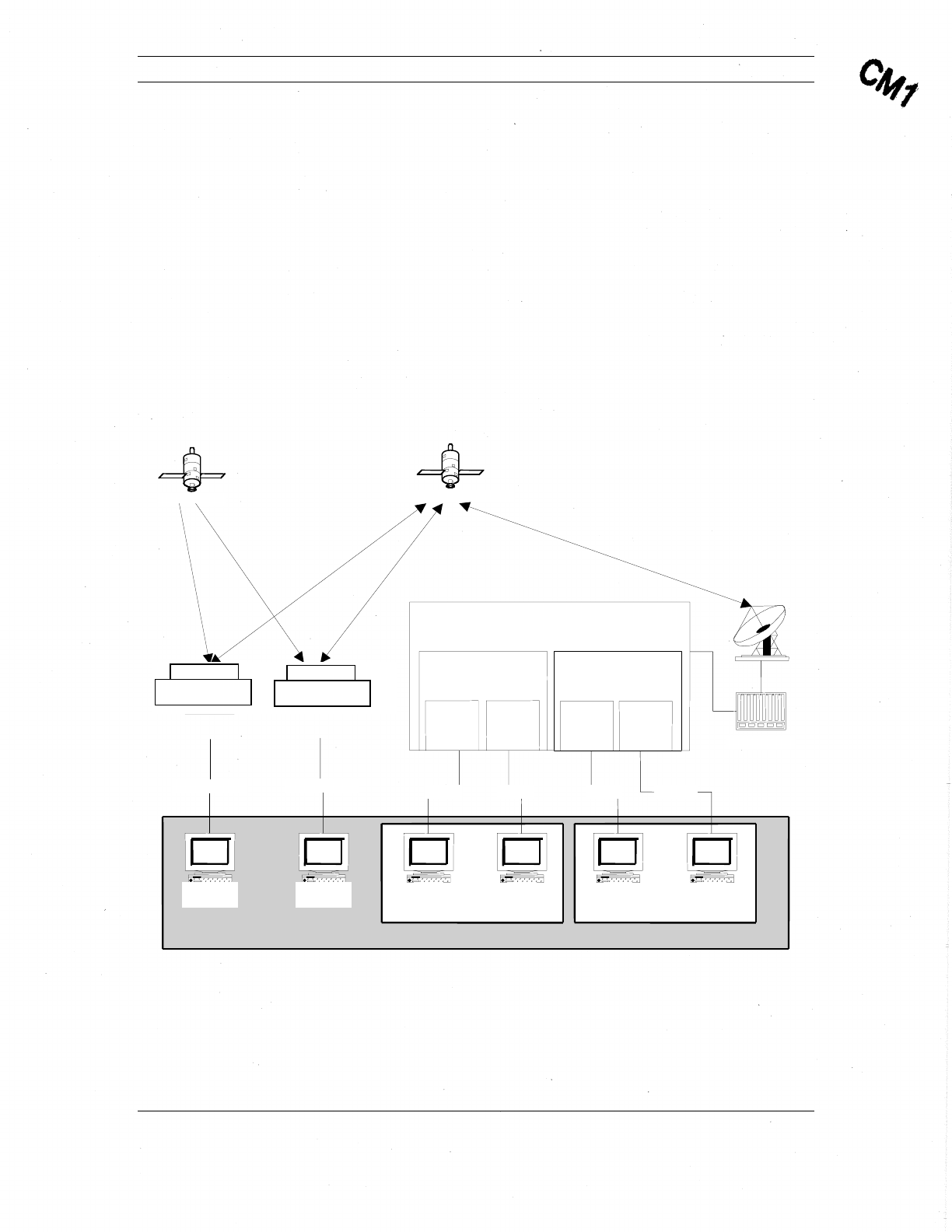
The following figure illustrates the Comtech Network Architecture and is followed by a
description of the network components.
Figure 1: Comtech Network Architecture.
Application Development Area
Customer
n Customer X
Communications Satellite
GPS
Satellite
Transceiver
Client
Transceiver
Customer
X
RS
422
Serial
A
gent
Client
A
gent
Client
A
gent
Client
A
gent
Client
TCP/IP
Transceiver
Customer
n
TCP/IPP
Transceiver
Client
RS
422
Serial TCP/IP TCP/IP
Comtech Hub
Network Packet Switch
Agent X
Session
X-1 Session
X- n
Agent n
Session
n-1 Session
n-n
The Comtech Mobile Datacom Network consists of three main components:
• Network Packet Switch
• Hub
• Transceiver

Comtech Mobile Datacom Corporation CMDC-DOC-0138, Rev. B
© COMTECH MOBILE DATACOM CORPORATION Page 10 of 37
PROPRIETARY & CONFIDENTIAL
This is an unpublished work protected under the Copyright laws.
All rights reserved.
The Network Packet Switch (or Switch) is a set of ground station computers through
which all network traffic is routed. The Switch can support many different types of
connections:
• VSAT
• Internet
• Leased line
• Dialup
The Switch’s primary function is to handle the routing of network traffic. The Switch has
several processes to support this function. Of the processes running on the Switch, the
Agent process is the most important process to a customer. An Agent is one of the access
points a customer can use to send messages via the CMS. Section 2.3 describes the
functions and workings of an Agent in more detail. For security purposes, the Switches,
and therefore the Agents, are protected via a firewall.
The Comtech Hub is connected to the Switch. The Hub contains radio frequency (RF)
modulation and demodulation equipment. The Hub’s primary function is to transform
data into a radio frequency signal and a radio frequency signal into data. The Hub takes
outgoing TCP/IP packets from the Switch and transforms them into signals that are then
transmitted up to the satellite and down to a transceiver. The Hub also takes the incoming
signals sent from a transceiver via satellite and transforms them into TCP/IP packets that
can be processed by the Switch.
The transceiver is a customer’s other access point into the Comtech Network. A
transceiver’s primary function is to act as an antenna. A transceiver sends and receives
messages as directed by the client application that is connected to it. A transceiver also
has some on-board processing capabilities that allow it to send messages autonomously.
Section 2.4 describes the functions and workings of a transceiver in more detail.
2.3. Agent
An Agent is a process that runs on the Network Packet Switch. An Agent’s main function
is to manage message traffic for a given customer. Typically, each customer is assigned a
separate agent, thereby creating a VPN (Virtual Private Network) for each customer.
Customers cannot access each other’s Agents, unless the customer instructs Comtech to
permit such access.
The Agent performs the following functions to incoming messages:
• Accepts messages from transceiver or client connections
• Decrypts messages
• Delivers messages to their intended recipients

Comtech Mobile Datacom Corporation CMDC-DOC-0138, Rev. B
© COMTECH MOBILE DATACOM CORPORATION Page 11 of 37
PROPRIETARY & CONFIDENTIAL
This is an unpublished work protected under the Copyright laws.
All rights reserved.
The Agent performs the following functions to outgoing messages:
• Accepts messages from a client connections
• Encrypts the outgoing messages
• Sends messages through the Comtech network
Customers with specific processing requirements often have applications that connect to
the Agent. Each Agent has a process focused on listening on a specific TCP/IP port for
incoming client connections. Once an Agent receives an incoming connection, the Agent
forks (spawns) a child dedicated to servicing the client. This child process will continue
to service the client until the client application closes the TCP/IP connection. An Agent
can service up to 64 separate connections.
2.4. Transceiver
The MTM-203 Transceiver is a compact module that can easily be integrated into a
device. The transceiver’s primary function is to allow users and applications the ability to
send and receive messages via satellite. Using the GPS receiver, a transceiver can
“piggyback” location information on each message. A transceiver can also transmit its
location automatically.
The MTM-203 Transceiver module provides the following features:
• Small, two-sided board to easily integrate into a device
• Includes a single serial interface, at TTL levels
• Supports API commands using the serial interface
• Contains internal GPS device with capability to connect to an external GPS
device. The internal GPS pass-through model provides an RF signal to the
external GPS for both L1 and L2 frequencies
• Low power operation to minimize battery consumption and can connect to an
external power supply
• Ensures GPS receiver can receive RHCP signal, regardless of communication
channel polarization
• Allows for dual polarization antenna use
• Provides overload protection on the receive channel to prevent LNA burn-out
for large signals
• Allows for FPGA code loading via an external serial port at rates higher than
normal API rates
• Ensures a short power on to operational period, including less than 1 sec
FPGA load times
Comtech Mobile Datacom Corporation CMDC-DOC-0138, Rev. B
© COMTECH MOBILE DATACOM CORPORATION Page 12 of 37
PROPRIETARY & CONFIDENTIAL
This is an unpublished work protected under the Copyright laws.
All rights reserved.
2.4.1. Transceiver Subsystems
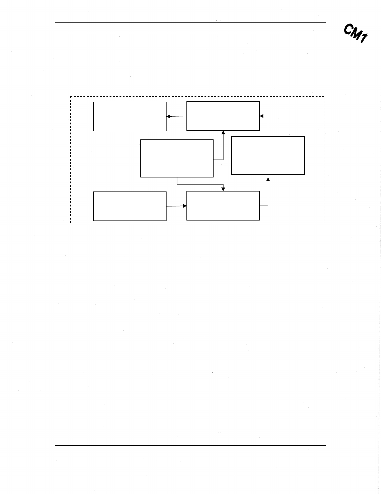
The following figure illustrates the MTM-203 Transceiver subsystems. A description of
each subsystem follows.
Figure 2: MTM-203 Block Diagram of Subsystems.
2.4.2. High Power Amplifier (HPA) Subsystem
The HPA subsystem is comprised of amplifiers and converter circuitry to boost signal
sufficiently for transmissions.
2.4.3. Modulator Subsystem
The Modulator subsystem processes the signal from the baseband subsystem for
amplification by the HPA.
2.4.4. Synthesizer Subsystem
The Synthesizer subsystem provides the timing signals to synchronize the other
subsystems.
2.4.5. Baseband Subsystem
The Baseband subsystem is comprised of a Field Programmable Gate Array (FPGA) and
Central Processing Unit (CPU), which process the received and transmitted signals.
2.4.6. Low Noise Amplifier (LNA) and R/F I/O Mux Subsystem
The LNA, R/F, and I/O Mux subsystem processes the receive signal for use by the down
converter.
HP
A
(Amplifiers and Related
Circuitry)
Modulato
r
D/A and
Up-converter
LNA and RF I/O MUX
Including R/L and T/R
Switches
Down Converter & A/D
Synthesize
r
DDS and Related Circuitry
(shared between the
transceiver and receiver)
Baseband
(FPGA and CPU)

Comtech Mobile Datacom Corporation CMDC-DOC-0138, Rev. B
© COMTECH MOBILE DATACOM CORPORATION Page 13 of 37
PROPRIETARY & CONFIDENTIAL
This is an unpublished work protected under the Copyright laws.
All rights reserved.
2.4.7. Down Conversion and A/D Subsystem
The down converter and A/D subsystem processes the received signal for use by the
baseband.
2.5. Transceiver Operational Considerations
The transceiver enables satellite communications via an external antenna. Therefore, the
external antenna must be able to “see” the satellite in order to function properly. The
transceiver is designed to operate outdoors with an unobstructed view of the southern
sky. Some obstacles that can block the transceiver include tall buildings, tunnels, parking
garages, and dense forests. The transceiver may operate inside of a building provided the
antenna is positioned in a window with a view of the satellite, and provided the window
is not coated with a reflective material.
In addition to large visible obstacles, multi-path interference may hinder a transceiver
from receiving optimally. Multi-path interference occurs when multiple signals arrive at
an antenna having traversed different paths. Multi-path is due to reflections from objects
(surfaces) located near the transceiver. In most cases, moving the transceiver a few feet
(sometimes inches) in one direction or another will alleviate the interference caused by
multiple signals.
NOTE: Since the communications receiver and the GPS receiver are two separate
receivers, each performs (receives its signal) independently. A partition of the front-
end receiver is common between the GPS path and the message receiver path.
Therefore, it is possible for the antenna to receive messages but not have a valid
GPS fix. The reverse is also true.
NOTE: Comtech’s transceivers are designed to operate in the United States of
America in accordance with Federal Communications Commission (FCC)
regulations (authorization pending as of 05/16/06). To operate in the U.S., the MTM-
203 transceiver must adhere to FCC regulations regarding mobile radio
transmitters which use L-Band. By regulation, a transceiver operating in the U.S.
must be configured so that it will not transmit if its receiver is not in lock (locked
onto the satellite signal). Therefore, any Comtech transceiver operating in the U.S. is
configured not to transmit if the transceiver’s receiver is out-of-lock. Transceivers
may be configured differently in other countries.
CAUTION: External antennas should not be positioned within six feet of each
other. Antennas that are too close together may result in equipment damage.
CAUTION: Do not place equipment directly on wet ground, snow, or ice for
operations.
2.6. Client API and Command Set (Agent and Transceiver)
As previously stated, the CMS provides two basic access points, the Agent and the
transceiver. Each access point has its own Application Programming Interfaces (APIs).
These APIs allow external applications to use the platform as a conduit for application

Comtech Mobile Datacom Corporation CMDC-DOC-0138, Rev. B
© COMTECH MOBILE DATACOM CORPORATION Page 14 of 37
PROPRIETARY & CONFIDENTIAL
This is an unpublished work protected under the Copyright laws.
All rights reserved.
message exchange and for other supported functions (such as mobile GPS tracking). The
APIs may be engaged directly by users or by application programs.
In the spirit of the traditional client-server model, this document will use the general
terms ‘client’ and ‘server’ when referring to components of a Comtech messaging
implementation. In this context, a client will generally refer to any external entity that
engages an Agent or Transceiver API. This may include any of the following variations:
• A user accessing the API directly (typically via a terminal communications
utility such as TELNET).
• A user interface application that bridges between the API and a user.
• An automated application.
The term ‘server’ will generally refer to a specific instance of an Agent or Transceiver
API.
The Agent and Transceiver components each provide an API for external clients. Both
APIs consist of an interactive command line interpreter (CLI) that is generally activated
when a client establishes a connection.
The CLI presents a command prompt and allows the client to issue specific commands to
the server process of the respective Agent or Transceiver. The server will generally
respond to client commands with action (such as changing a session setting), data output
(such as displaying current settings), or both. Certain commands may prompt the client
for additional input.
The CLI operates synchronously. It issues a new command prompt only after it
completes execution of the previous command. The client must wait for a prompt before
submitting subsequent commands (i.e., the CLI does not support type-ahead).
In certain situations, the CLI may present unsolicited information to the client while the
client is issuing commands (primarily in the case of message arrival). However, this
behavior can be suppressed and/or controlled in most cases.
Interaction between client and API will usually be discussed in the context of a ‘session’.
In the case of an Agent, a session is generally defined as the period of the TCP/IP
connection between client and Agent. In the case of a Transceiver, a session is best
described as the operational period of the transceiver following boot-up.
The session concept implies a period in which the configuration of the Agent or
Transceiver (with respect to commands issued by the client) is retained. In the case of an
Agent, all session contexts are lost when the TCP/IP connection is broken. In the case of
the Transceiver, session context is generally retained as long as the transceiver is
continuously operating – whether or not the client is actively engaging the serial
interface. (Note: The CMDC concept of session may not necessarily apply to that of a
particular client application.)

Comtech Mobile Datacom Corporation CMDC-DOC-0138, Rev. B
© COMTECH MOBILE DATACOM CORPORATION Page 15 of 37
PROPRIETARY & CONFIDENTIAL
This is an unpublished work protected under the Copyright laws.
All rights reserved.
3. Integrating the MTM-203 into a Device
3.1. Purpose of this Section
The purpose of this section is to provide guidance for integrating the Comtech Mobile
Datacom MTM-203 Transceiver Module into a device. The focus of this section is to
describe transceiver integration, including material requirements and a detailed
description of the MTM-203 transceiver interface and connectors.
3.2. Needed Materials for Integration
The following materials are needed to integrate the MTM-203 Transceiver Module into a
device:
• Antenna, cable, and connectors
• Power supply
• Optional Military GPS Receiver
3.2.1. MTM-203 Interface Requirement
Required Performance Characteristics for Antenna
Gain +1dBiC minimum for elevation angles between 20 degrees and 60
degrees
Impedance 50 ohms
Polarization for
use in the USA Right-hand circularly polarized (RHCP). The transceiver can be
operated with a single RHCP antenna connected to the RHCP port
or a dual pole antenna with both RHCP and LHCP ports connected.
Polarization for
use outside the
USA
RHCP is required as a minimum. LHCP can be added for
additional satellite coverage options.
Connector Type Cable connectors must be compatible with the type SSMB coaxial
connectors on the MTM-203 module antenna ports. Manufacturer
and part number used for these parts are AEP p/n 7209-1511-050
(alternate supplier is COAXICOM p/n 6M230SL-1).
Max Loss Total combined loss for cable and connections should be no more
than .5dB at 1.6 GHz
Tx Modulation BPSK DS-SS
Tx Frequency 1626.5 – 1660.5 MHz
Tx Level 36.9 dBm Max

Comtech Mobile Datacom Corporation CMDC-DOC-0138, Rev. B
© COMTECH MOBILE DATACOM CORPORATION Page 16 of 37
PROPRIETARY & CONFIDENTIAL
This is an unpublished work protected under the Copyright laws.
All rights reserved.
Rx Modulation BPSK DS-SS
Rx Frequency 1525 – 1559 MHz – Communication Channel
1575.42 +/- 13 MHz - GPS L1
1227.60 +/- 13 MHz - GPS L2
Rx Level -131 dBm
GPS Rx
Modulation BPSK DS-SS
GPS Rx Frequency 1525 – 1559 MHz – Communication Channel
1575.42 +/- 13 MHz - GPS L1
1227.60 +/- 13 MHz - GPS L2
GPS Rx Level -107 dBm
Approvals Must pass Comtech System/Network Compliance Approval Process
to be fielded outside of test/development environment.
The wire gauge should be 20 AWG for the cable connection to the MTM-203’s
24 position control interface connector (P1) (Molex, Part Number 87831-2420).
3.2.2. External Power Supply Requirements
The VBAT input to the MTM-203 Transceiver module must be between 6.5V to 15
VDC.
3.2.3. External GPS Requirements
An external GPS RF 50 ohm, -107 dBM (see Table 4) device may be connected to the
MTM-203 transceiver. The cable from the External GPS Input port should have an
SSMB connector.
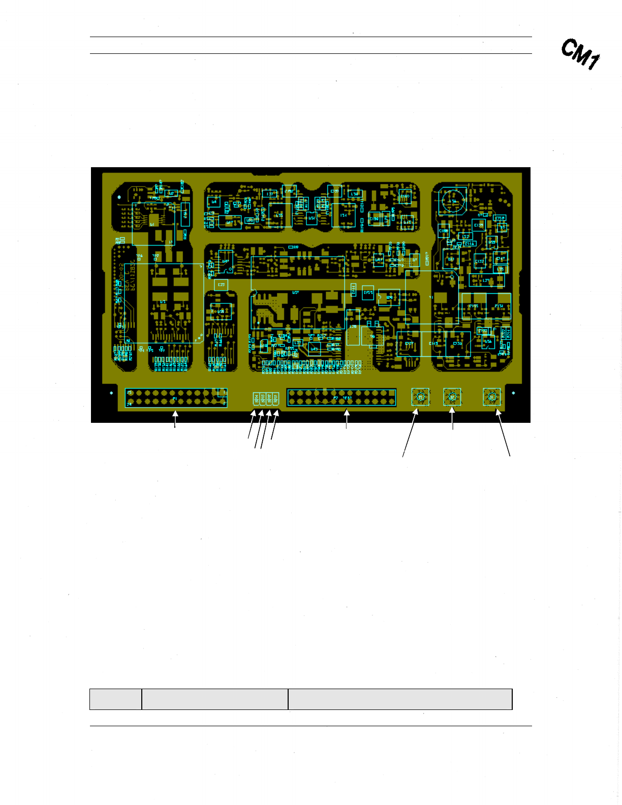
3.3. Physical Interface Description
There are two hardware interface points on the MTM-203 Transceiver Module (Figure
3): the Control Interface and the Antenna Interface.
The Control Interface manages the communication between the data source and the
transceiver. This interface is also used for loading configuration data and updating the
firmware of the module. Power for the MTM-203 Transceiver Module must be provided
through this interface.
The antenna interface consists of three coaxial connectors, two of which deliver the
received signal from either a left hand (LH) or right hand (RH) circularly polarized
(RHCP) antenna to the corresponding low noise amplifier (LNA) circuitry, and the
transmit signal from the High Power Amplifier (HPA) to the antenna. Since the module
operates only in half-duplex mode, only transmit or receive signal will be present at this
interface at any given time. The RF signal from the RHCP antenna is also fed to the on-
Comtech Mobile Datacom Corporation CMDC-DOC-0138, Rev. B
© COMTECH MOBILE DATACOM CORPORATION Page 17 of 37
PROPRIETARY & CONFIDENTIAL
This is an unpublished work protected under the Copyright laws.
All rights reserved.
board GPS device. The transceiver may be configured to automatically switch from LH
to RH (or vice versa) by using the API command to implement worldwide autonomy.
The third coaxial connector is an external GPS input for feeding the RF signal to an
external GPS unit.
Figure 3: MTM-203 PC Board showing connectors and LEDs.
3.4. Mounting the Transceiver in a Device
Appendix B provides a mechanical drawing of the MTM-203 module describing
mounting holes that should be used to secure the module in a device.
3.5. Connecting to the Transceiver
3.5.1. Control Interface
The Control Interface is implemented in the P1 connector (Molex, Part Number 87831-
2420) located on the topside of the MTM-203 module. The following table describes the
P1 connector pin-outs and the function of each pin on this connector.
Table 2: P1 Control Interface Pin-outs
Pin-outs Input/Output (I/O) Pin Description
LED-D P2 Connector
External GPS
Connector (J1)
A
ntenna-RHCP (J2)
Connector
A
ntenna-LHCP
(J3) Connector
LED-C
LED-B
P1 Connector LED-A

Comtech Mobile Datacom Corporation CMDC-DOC-0138, Rev. B
© COMTECH MOBILE DATACOM CORPORATION Page 18 of 37
PROPRIETARY & CONFIDENTIAL
This is an unpublished work protected under the Copyright laws.
All rights reserved.
Pin-outs Input/Output (I/O) Pin Description
1 N/A GND
2 Input VBATT (6.5 – 15 V)
3 N/A GND
4 Input VBATT (6.5 – 15 V)
5 Output LED-C – Flashes during configuration and
remains on once the console is configured
and ready. D3 LED on the PC board.
6 Output LED-A – Illuminates while transmitting
and illuminates during boot. D1 LED on
the PC board.
7 Output LED-B – Illuminates indicating that the
receiver is in lock and High-Level Data
Link Control (HDLC) is in-sync when lit.
D2 LED on the PC board.
8 Output AUX_PWR CNTL
9 Input IGN_SENSE
10 Input MAIN CNTL (ON/OFF) – Turns module
off at .5V. Turns module on at >1.5V. Do
not exceed 30V.
11 I/O User Defined: 0–3 V, 8 mA, max, 3 V
logic
12 I/O User Defined: 0–3 V, 8 mA, max, 3 V
logic
13 I/O User Defined: 0–3 V, 8 mA, max, 3 V
logic
14 I/O User Defined: 0–3 V, 8 mA, max, 3 V
logic
15 Input AUX UART RX IN – Future development
16 Output AUX UART TX OUT– Future
development
17 Input SER DAT IN – Supports communications
using Comtech API commands.
18 Output SER DAT OUT – Supports
communications using Comtech API
commands.

Comtech Mobile Datacom Corporation CMDC-DOC-0138, Rev. B
© COMTECH MOBILE DATACOM CORPORATION Page 19 of 37
PROPRIETARY & CONFIDENTIAL
This is an unpublished work protected under the Copyright laws.
All rights reserved.
Pin-outs Input/Output (I/O) Pin Description
19 Output 3.3 V – Provides debugging. Not
recommended for any other use.
20 Output LED-D – FPGA LED
21 Input GPS Keep Alive – 1.95-3.6V (40 μA max.
at
3.3 V) external power supply to keep the
GPS device's real-time clock and backup
RAM. Connecting it to the
3.3 V on pin 19 will speed up the fix
acquisition of the GPS when using API
commands to control power to the internal
GPS module. Connect to ground if not
used.
22 NC
23 NC
24 NCU
3.5.2. LEDs
Figure 3 illustrates four LEDs: A–D, next to the P1 connector on the top-side of the
MTM-203 Transceiver Module. The function of LEDs A-C is also specified in Table 2.
LED-D indicates hardware receive lock from the FPGA. “On” indicates that the FPGA is
locked to the received signal. The LED will flicker if the signal is weak and the receiver
is reacquiring.
3.5.3. P2 Connector
Figure 3 shows a P2 connector between the LEDs and the antenna interface connectors.
The P2 connector was only available during development and is now disabled.
3.5.4. Antenna Interface
The antenna interface on the MTM-203 Transceiver consists of three coaxial connectors:
two connectors for an external antenna and a third connector for an external GPS module.
Antenna-LHCP (J3)
Connector J3 feeds the LHCP LNA circuitry when in receive mode and connects to the
LHCP HPA circuitry when the transceiver is in transmit mode.
Antenna-RHCP (J2)
Connector J2 feeds the RHCP LNA circuitry in the receive mode and connects to the
RHCP HPA circuitry when the transceiver is in transmit mode. The RHCP LNA also
feeds the internal GPS module as well as the J1 connector.

Comtech Mobile Datacom Corporation CMDC-DOC-0138, Rev. B
© COMTECH MOBILE DATACOM CORPORATION Page 20 of 37
PROPRIETARY & CONFIDENTIAL
This is an unpublished work protected under the Copyright laws.
All rights reserved.
The following table describes the electrical characteristics of the signal in transmit (TX)
and receive (RX) directions.
Comtech Mobile Datacom Corporation CMDC-DOC-0138, Rev. B
© COMTECH MOBILE DATACOM CORPORATION Page 21 of 37
PROPRIETARY & CONFIDENTIAL
This is an unpublished work protected under the Copyright laws.
All rights reserved.
Table 3: Antenna LHCP and RHCP TX and RX Signal Characteristics
Signal
Characteristic Transmit (TX) Receive (RX)
Modulation BPSK DS-SS BPSK DS-SS
Frequency 1626.5 – 1660.5
MHz 1525 – 1559 MHz – Communication Channel
1575.42 +/- 13 MHz - GPS L1
1227.60 +/- 13 MHz - GPS L2
Level 36.9 dBm Max -131 dBm
3.5.5. External GPS Connector
The third coaxial connector, J1, feeds the GPS signal to an external GPS module. The
signal output from this connector is only available when the unit is in the receive
mode. The following table describes the electrical characteristics of the signal for this
connector.
Table 4: External GPS Rx Signal Characteristics
Signal
Characteristics Receive
Modulation BPSK DS-SS
Frequency 1525 – 1559 MHz – Communication Channel
1575.42 +/- 13 MHz - GPS L1
1227.60 +/- 13 MHz - GPS L2
Level -107 dBm
3.6. Booting-up the Transceiver
When applying power to the MTM-203 module, or on system reboot, the transceiver
module will go through a standard boot sequence. Boot-up will last a minimum of five
seconds, but may take longer depending on the boot time-out setting.
The command to reboot the transceiver module is reboot. The following table describes
the various trace statements that display upon boot up.

Comtech Mobile Datacom Corporation CMDC-DOC-0138, Rev. B
© COMTECH MOBILE DATACOM CORPORATION Page 22 of 37
PROPRIETARY & CONFIDENTIAL
This is an unpublished work protected under the Copyright laws.
All rights reserved.
Table 5: Boot Trace Description
Line
# Boot Trace Statement Explanation
1 Default boot Displays type of boot: default, cold, or warm.
2 CMDC GEN2 Terminal Displays type of CMDC transceiver
3 Power On Self Test:
Passed Indicates a self test was performed, which
includes a test of the FPGA, RX PLL, TX PLL,
GPS, Temperature, and Battery. If a Self Test
failed, the response would show which systems
passed and which systems failed.
Example Failed Self Test:
> reboot
Reboot in progress....
Default boot - Watchdog reset
CMDC GEN2 Terminal
Power On Self Test: 0x20
FPGA: Passed
RX PLL: Passed
TX PLL: Passed
GPS: Passed
TEMPERATURE: Passed
BATTERY: Failed Code: 0x2
ID ok.
4 ID ok. Indicates that the transceiver module has been
provisioned with a permanent identity. If this
line does not state “ID ok,” the transceiver has
not been provisioned correctly.
5 >
>
>
Displays command prompts indicating system is
booting up.
6 >api reset Sets the transceiver to interactive mode with the
echo on (display commands). This mode saves a
user from typing the entire commands. As the
user types in the first few characters of a

Comtech Mobile Datacom Corporation CMDC-DOC-0138, Rev. B
© COMTECH MOBILE DATACOM CORPORATION Page 23 of 37
PROPRIETARY & CONFIDENTIAL
This is an unpublished work protected under the Copyright laws.
All rights reserved.
Line
# Boot Trace Statement Explanation
command, the transceiver will attempt to
interpret the characters and then prompt the user
with a known command.
7 > show version? Indicates that what follows are system software
versions.
8 Boot 2.2.E Indicates version of the boot loader the
transceiver is running.
9 Host 3.4.T Indicates version of the Host application that is
running.
10 ALTERA 0.227 Indicates version of the FPGA application that is
running.
11 RTOS 2.70 Indicates version of the receiver operating
system that is running.
12 > Displays the command prompt.
3.7. Provisioning
CMDC ships all transceivers fully provisioned. Provisioning establishes the profile of
configuration commands inherent to the transceiver as to its operation within the Agent.
These configuration settings also adhere to specific requests from the customer as to the
behavior of the transceivers interfacing with their software.

Comtech Mobile Datacom Corporation CMDC-DOC-0138, Rev. B
© COMTECH MOBILE DATACOM CORPORATION Page 24 of 37
PROPRIETARY & CONFIDENTIAL
This is an unpublished work protected under the Copyright laws.
All rights reserved.
4. Indicators and Diagnostics
4.1. Purpose of this Section
The purpose of this section is to provide basic diagnostics to integrate the MTM-203 into
a device. The focus of this section describes how to use the LEDs to interpret transceiver
activity and verify system operations.
4.2. Using LEDs
There are three Light Emitting Diodes (LEDs) on the top side of the transceiver between
the P1 and P2 connectors (see Figure 3). Each LED represents a transceiver state.
4.2.1. LED A
LED A represents the status of the transmitter. When LED A is on (flickers), the
transceiver is transmitting. When LED A is off (not illuminated), the transceiver is not
transmitting. Upon each transmission, LED A will turn on for a few milliseconds.
4.2.2. LED B
LED B represents the status of the receiver. When LED B is on solidly (not flickering),
the receiver is in-lock. When LED B is on, but the light is flickering, the receiver is out-
of-lock. Since the transceiver is half-duplex, upon each transmission, the LED will turn
off for a few milliseconds, indicating the receiver is momentarily out-of-lock.
4.2.3. LED C
LED C represents the status of the console or the interface. When LED C is on, the
transceiver’s interface is available. If LED C is off continuously, the transceiver’s
interface is unavailable and generally indicates a buffer overflow.
4.2.4. Interpreting LEDs during Boot-Up
If the LEDs are operating in the led normal state, during boot up, the LEDs will cycle a
number of times in what appears to be a random order. Although the process appears
random, the LEDs are actually showing the boot up process of the firmware in the
transceiver. If none of the LEDs are illuminating at boot up, the LEDs may be in the led
blackout state. If the LEDs are supposed to be in the led normal state, check the
cables you are using, the transceiver is likely not getting adequate power.
4.3. Displaying Receiver Lock Status
The transceiver’s interface can be configured to display status of the receiver, (e.g., the
receiver is in- or out-of-lock with the satellite). The command show receiver status
queries the receiver one time to determine if it is in-lock or out-of-lock. The transceiver
will respond with:

Comtech Mobile Datacom Corporation CMDC-DOC-0138, Rev. B
© COMTECH MOBILE DATACOM CORPORATION Page 25 of 37
PROPRIETARY & CONFIDENTIAL
This is an unpublished work protected under the Copyright laws.
All rights reserved.
Receiver not in lock Indicates that receiver does not have a proper link to the satellite.
Receiver in lock Indicates that receiver has a proper link to the satellite.
Rather than a one-time query, the operator may want to be alerted of changes in real-
time. The command alert receiver lock will instruct the transceiver to display
statements each time the receiver changes lock states. The command to stop the
transceiver from displaying the status of the receiver is ignore receiver lock.
If the receiver is not in-lock, the operator should attempt to move the receiver to a better
position. The parameter to alert or ignore the receiver status is managed by the Host
processor. To make this parameter available after reboot, the client should issue the save
configuration command.
4.4. Measuring Signal to Background Noise
The measure cno command performs a signal (carrier) to noise ratio (C/No)
measurement or measurement of the signal to background noise, using a pilot signal from
the satellite. For this measurement to work, the frequency of the pilot for the proper
satellite and beam must be set in the transceiver.
4.5. Interpreting Signal to Noise Measurement
The command measure cno prompts the user for a Repeat Count. The repeat count
indicates the number of C/No measurements the user wishes to execute. A repeat count
of three or more is recommended. The output of the command will look similar to the
following:
Measuring C/No at 1556060 kHz, please wait...
Frequency = -1812 Hz
Power = 2.78 dB
C/No = 33.88 dB-Hz
The first line of the output shows which C/No frequency the transceiver is using to
measure. Three measurements follow: Frequency, Power, and C/No. Frequency should be
close to 10,000 Hz (+/- 400 Hz). Carrier power is the second measurement. The third and
final measurement is the C/No. A result of greater than 40 dB-Hz indicates the
transceiver is performing as expected.

Comtech Mobile Datacom Corporation CMDC-DOC-0138, Rev. B
© COMTECH MOBILE DATACOM CORPORATION Page 26 of 37
PROPRIETARY & CONFIDENTIAL
This is an unpublished work protected under the Copyright laws.
All rights reserved.
5. Troubleshooting
5.1. Purpose of this Section
The purpose of this section is to provide guidance with troubleshooting problems when
integrating the MTM-203 transceiver. The focus of this section is to describe common
error messages and how to systematically verify settings to resolve problems.
5.2. Error Messages
The transceiver will display an error message if an incorrect command has been entered.
An incorrect command is usually a command in which the syntax was wrong or
incomplete. When the transceiver is in API interactive mode and it receives an
incomplete command, it responds with the following message:
Unrecognized command
When the transceiver is in API line mode and it receives an incorrect command, it
provides a standard response in two parts. The first part is the text string “Bad Cmd” and
the second part is the hex equivalent of the characters of the command that the client
attempted to issue.
Example: While in API line mode, the user wants to see a transceiver’s identities.
Rather than issuing the show identities command, the user submits the string “show id”.
The transceiver responds with the following message:
Bad Cmd: "73 68 6F 77 20 69 64"
The following table describes common transceiver error messages.
Table 6: Error messages
Error Message Source of Error
Can't transmit: Receiver not in lock. The transceiver is out of lock and the
transceiver is only permitted to transmit
when the receiver is in lock.
SEND FAILED: Bad or missing TO. The active DSP set does not have a
"Default to" or "Default from" set.
5.3. Troubleshooting the MTM-203
To troubleshoot the MTM-203 Transceiver Module, follow the steps below as applicable
until the transceiver is corrected or you confirm proper functionality.
1. Verify frequency and receiver lock status.
a. Open Hyperterminal. Click Start / Programs / Accessories /

Comtech Mobile Datacom Corporation CMDC-DOC-0138, Rev. B
© COMTECH MOBILE DATACOM CORPORATION Page 27 of 37
PROPRIETARY & CONFIDENTIAL
This is an unpublished work protected under the Copyright laws.
All rights reserved.
Communications / Hyperterminal.
b. Select ComPort.
c. Type show receiver status and press Enter.
d. Verify status for “Receiver in lock”.
e. If receiver is not-in-lock, type list settings.
The following is an example response.
f. Verify the frequency you are using is active.
Note: The last setting displayed in the above example is your active
frequency, “Settings Number: 1”.
g. If your frequency is not “Active”, type edit dsp settings and press
Enter.
h. Type load dsp settings and press Enter.
i. Type the Setting Number that corresponds to desired frequency and
press Enter.
The following is an example response indicating the configuration is
loaded.
Loaded DSP configuration 1.
j. Type activate dsp settings and press Enter.
k. Type save configuration and press Enter.
l. Type reboot and press Enter to reboot the transceiver.
> list settings?
1: Tx 1633585/84375/32 I-R, Rx 1532085/84375/32 I-R, 50, To: 1 (BFIELD), From: 3 (TEST-016)
1: Tx 1633585/84375/32 I-R, Rx 1532085/84375/32 I-R, 50, [Active], To: 1 (BFIELD), From: 3 (TEST-016)
2 is available.
>

Comtech Mobile Datacom Corporation CMDC-DOC-0138, Rev. B
© COMTECH MOBILE DATACOM CORPORATION Page 28 of 37
PROPRIETARY & CONFIDENTIAL
This is an unpublished work protected under the Copyright laws.
All rights reserved.
2. If the frequency setting was correct and/or the receiver showed not-in-
lock, follow these steps.
a. Open Hyperterminal. Click Start / Programs / Accessories /
Communications / Hyperterminal.
b. Type start demod reporting and press Enter.
A response displays asking “Interval?” The “Interval” is a parameter
that indicates the interval (in seconds) that the demod statistics are
displayed.
c. Type 5 to indicate second intervals.
d. Allow demod reporting to run for about one minute.
The following is an example demod report set for 5 second intervals.
5 sec, Eb/No 7.9 dB Quality 193, Frequency Offset 330
5 sec, Eb/No 7.8 dB Quality 193, Frequency Offset 330
5 sec, Eb/No 8.1 dB Quality 193, Frequency Offset 330
5 sec, Eb/No 7.7 dB Quality 193, Frequency Offset 330
5 sec, Eb/No 8.0 dB Quality 180, Frequency Offset -330
5 sec, Eb/No 7.9 dB Quality 195, Frequency Offset 330
5 sec, Eb/No 0.8 dB Quality 64, Frequency Offset 330
e. Type stop demod reporting and press Enter.
f. If an Eb/N0 less than 4.0 is displayed, check the placement of the
antenna. Is something obstructing the view of the southern sky? If so,
move the obstruction or the antenna.

Comtech Mobile Datacom Corporation CMDC-DOC-0138, Rev. B
© COMTECH MOBILE DATACOM CORPORATION Page 29 of 37
PROPRIETARY & CONFIDENTIAL
This is an unpublished work protected under the Copyright laws.
All rights reserved.
3. For confirmation of settings, proceed as follows:
a. Type show dsp settings and press Enter.
A list of settings displays. The following is an example display of DSP
settings.
> show dsp settings?
Config Number: 1
Receive Frequency: 1532085000
Receive Chip Rate: 84375
Receive Spread Ratio: 32
Transmit Frequency: 1633585000
Transmit Chip Rate: 84375
Transmit Spread Ratio: 32
Transmit Acquisition Period: 256
Transmit Acquisition Repeats: 1
Transmit Gain: 100
Transmit Auth: 000000
Default From: TEST-016
Default To: BFIELD
C/N0 Frequency: 1556060000
Active VCTCXO: -990
In-Lock Threshold: 30
Out-Lock Threshold: 20
Retry count 4, interval 20
Repeat count 1, interval 5
Repetitions: 1
Freewheel: 180
Scan Dwell: 4000
Config Flags: 000305
Number: 1, Search Step: 40, Search Dwell: 0
Manual Tuning
Lock to Strongest with Acquisition.
Stored VCTCXO: -442
>
b. Verify settings are correct.

Comtech Mobile Datacom Corporation CMDC-DOC-0138, Rev. B
© COMTECH MOBILE DATACOM CORPORATION Page 30 of 37
PROPRIETARY & CONFIDENTIAL
This is an unpublished work protected under the Copyright laws.
All rights reserved.
6. Customer Support Contact Information
If you have questions concerning this document, please contact CMDC’s Customer
Support line at 1-888-428-2101 or send an email to cservice@comtechmobile.com.

Comtech Mobile Datacom Corporation CMDC-DOC-0138, Rev. B
© COMTECH MOBILE DATACOM CORPORATION Page 31 of 37
PROPRIETARY & CONFIDENTIAL
This is an unpublished work protected under the Copyright laws.
All rights reserved.
7. Warranty
Comtech Mobile Datacom Corporation is obligated, under the provisions of the Warranty
for items delivered pursuant to specific contracts, to repair or replace or otherwise
provide a remedy for warranted items only if damage or loss results from or is caused by
the warranted item. Comtech is not obligated to provide repair, replacement or other
remedies in the event that damage or loss is the result of or is caused by actions or events
other than the warranted item, to include such causes as (1) misuse or abuse of the item
beyond the use contemplated in the Specification; (2) accidental damage. To include
aircraft crashes; (3) combat damage; (4) natural disasters, to include flood, earthquake,
hurricane, tornado; and (5) fires or explosions not originating on or within the warranted
item.
Comtech Mobile Datacom Corporation CMDC-DOC-0138, Rev. B
© COMTECH MOBILE DATACOM CORPORATION Page 32 of 37
PROPRIETARY & CONFIDENTIAL
This is an unpublished work protected under the Copyright laws.
All rights reserved.
Appendix A – Specifications
Power Specifications
Power Parameters Specification Maximum Current
VBATT input 6.5 – 15 VDC 2.5 Amp Maximum
Environmental / Mechanical Specifications
Environmental / Mechanical
Parameters Specification
Operating Temperature -40 – 71°C
Storage Temperature -50 – 85 °C
Input/Output (I/O) Specifications
I/O Parameter Voltage Max Current Signaling Comment
Serial Tx 0–3 V 3 V logic
Serial Rx 0–3 V 3 V logic
Serial ground 0 V
RF-A (RHCP) 50 ohm load Max Tx – 4 W
Max noise figure
– 2.0 dB
RF-B (LHCP) 5 ohm load Max Tx – 4 W
Max noise figure
– 2.0 dB
Digital I/O-1 0–3 V 8 mA, max 3 V logic General purpose
I/O
Digital I/O-2 0–3 V 8 mA, max 3 V logic General purpose
I/O
Digital I/O-3 0–3 V 8 mA, max 3 V logic General purpose
I/O
Digital I/O-4 0–3 V 8 mA, max 3 V logic General purpose
I/O
Shutdown 0–5 V High=shutdown 5 V tolerant
input
Comtech Mobile Datacom Corporation CMDC-DOC-0138, Rev. B
© COMTECH MOBILE DATACOM CORPORATION Page 33 of 37
PROPRIETARY & CONFIDENTIAL
This is an unpublished work protected under the Copyright laws.
All rights reserved.
I/O Parameter Voltage Max Current Signaling Comment
Ignition Sense 0-3 V 0 V= ignition
on1
LED-A 0-3 V 5 mA, max 3 V = on LED – “Transmit
On” while
transmitting.
Also lights
during boot. D1
LED on the PC
Board.
LED-B 0-3 V 5 mA, max 3 V = on LED – “Receive
Lock” Software
debounced,
receive in lock
and HDLC in-
sync when lit.
D2 LED on the
PC Board.
LED-C 0-3 V 5 mA, max 3 V = on LED – Console
status flashes
during
configuration
and then stays on
permanently
once configured
and ready. D3
LED on the PC
Board
GPS RF 50 ohm TBD External GPS
Satellite Channel Specifications
Channel
Parameters Return Link Forward Link Comment
KHz from
Center
Frequency
dB
Relative
to
Carrier
1 This signal is intended to be used with an inverting opto-isolator to monitor a vehicle ignition sense
signal.

Comtech Mobile Datacom Corporation CMDC-DOC-0138, Rev. B
© COMTECH MOBILE DATACOM CORPORATION Page 34 of 37
PROPRIETARY & CONFIDENTIAL
This is an unpublished work protected under the Copyright laws.
All rights reserved.
Channel
Parameters Return Link Forward Link Comment
0.3 -43.0
1.0 -54.0
10.0 -74.0
Transmit
phase noise
100.0 -94.0
Based on a
10° peak
phase noise
value (6.5
degree
average)
Transmit
out-of band 1525.0 and
below -85 FCC part 25
& ETSI
EN301-681
v01.03.02v
Specificatio
n
Other
emissions FCC Part 15 & 25, ETSI
EN301-681 v01.03.02v FCC &
ETSI
specificatio
n
Regulatory Compliance
The MTM-203 Transceiver Module has been designed to meet the following FCC and
ETSI compliance standards:
• FCC Part 15 and 25
• ETSI EN301-681 v01.03.02v Specification
• SAJ1113-13, 1455-4.1, 4.9, 4.10, 4.10.3.1
• MIL-STD 810F – High Temp/Low Temp Operation and Storage, Resonance
Survey, Sine-on-Random Vibration, Functional Shock, Crash Hazard Shock,
Bench Handling Shock, Humidity, Temperature Shock, Non-Operational Low
Pressure, Transit Drop Shock
This device has been tested for compliance and certified under FCC Part 25. Any
changes or modifications to the unit not expressly approved by Comtech Mobile Datacom
may void the user’s authority to operate the equipment.
Antennas: Use only the supplied or an approved replacement antenna. Unauthorized
antennas, modification or attachments could cause damage and may violate regulations.
RF Exposure: This unit must be operated with a minimum separation distance of 20 cm
from a person’s body.
Comtech Mobile Datacom Corporation CMDC-DOC-0138, Rev. B
© COMTECH MOBILE DATACOM CORPORATION Page 35 of 37
PROPRIETARY & CONFIDENTIAL
This is an unpublished work protected under the Copyright laws.
All rights reserved.
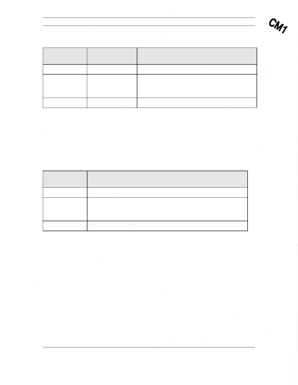
Appendix B – Mechanical Drawings
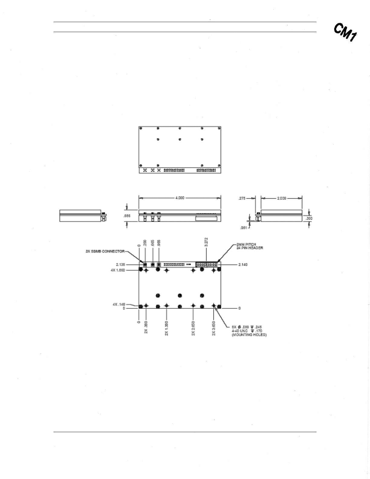
Physical Description
This section provides a physical description of the MTM-203 Transceiver Module. This
includes the physical size, location of components, and mounting holes (Figure 4) and a
description of the shield housing (Figure 5).
Figure 4: MTM-203 Transceiver, Top Level Mechanical View 1
Comtech Mobile Datacom Corporation CMDC-DOC-0138, Rev. B
© COMTECH MOBILE DATACOM CORPORATION Page 36 of 37
PROPRIETARY & CONFIDENTIAL
This is an unpublished work protected under the Copyright laws.
All rights reserved.
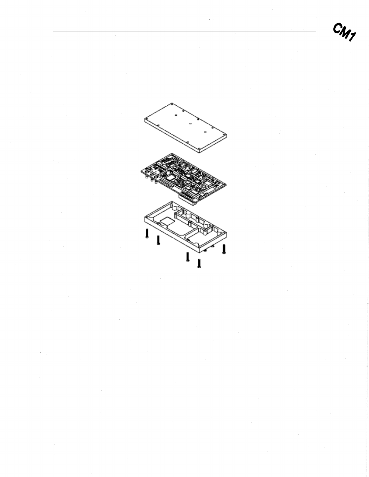
The MTM-203 Transceiver comes with metal upper and lower shields that have tamper
evident seals (see Figure 5). While the shields provide some protection against dust, it is
not intended to have direct exposure to the environment. The MTM-203 module should
be integrated into housing for a larger system.
Figure 5: MTM-203 Transceiver, Top Level Mechanical View 2

Comtech Mobile Datacom Corporation CMDC-DOC-0138, Rev. B
© COMTECH MOBILE DATACOM CORPORATION Page 37 of 37
PROPRIETARY & CONFIDENTIAL
This is an unpublished work protected under the Copyright laws.
All rights reserved.
Glossary
API – Application Programmers Interface
CLI – Command Line Interpreter
CMDC – Comtech Mobile Datacom Corporation
CPU – Central Processing Unit
DDS – Direct Digital Synthesis
FCC – Federal Communications Commission
FPGA – Field Programmable Gate Array
GPS – Global Positioning System
HDLC – High-Level Data Link Control
HPA – High Power Amplifier
IF – Intermediate Frequency
LED – Light Emitting Diode
LH – Left Hand
LHCP – Left-Hand Circularly Polarized
LNA – Low Noise Amplifier
RH – Right Hand
RHCP – Right-Hand Circularly Polarized
RF – Radio Frequency
TCP/IP – Transmission Control Protocol/Internet Protocol
VBAT – Voltage from Battery