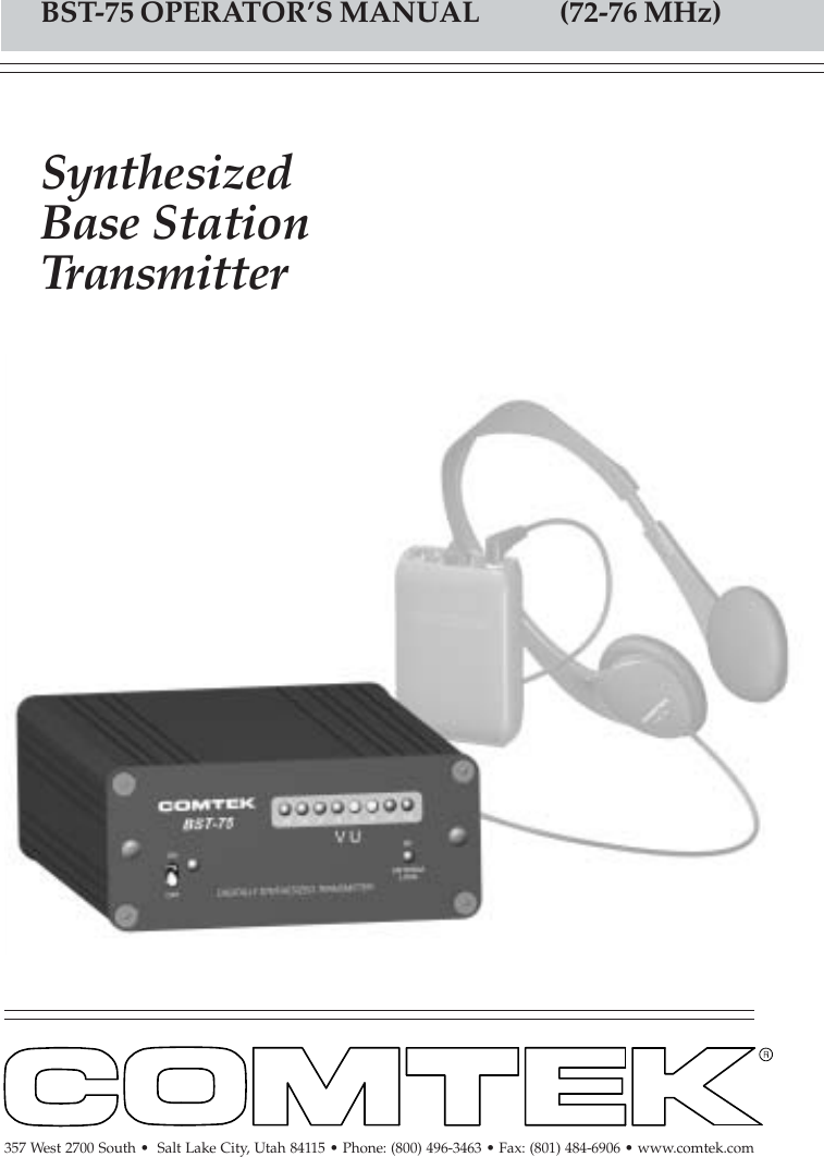
Comtek Communications Technology BST75 Transmitter User Manual Drawing dwg

Comtek Communications Technology Inc Transmitter Drawing dwg

USERS MANUAL

SynthesizedBase StationTransmitterBST-75 OPERATOR’S MANUAL             (72-76 MHz)357 West 2700 South •  Salt Lake City, Utah 84115 • Phone: (800) 496-3463 • Fax: (801) 484-6906 • www.comtek.com
© 2005 COMTEK® All rights reservedPrinted in U.S.A. 0105BST75TABLE OF CONTENTSIntroduction  ...........................................................Equipment Placement  ...............................................Power Requirements  .......................................................Remote Antenna  ......................................................Screw-in Whip Antenna  ............................................Audio Input Connections  ...............................................Audio Adjustments  ...............................................Audio Processing Circuit  ..........................................Front and Rear Panel Facilities  ........................................Frequency Information  ..........................................Accessories  ..........................................................Specifications  ......................................................Warranty and Service  ...............................................122334456-78-910-111213
The BST-75 mini base station transmitter meets the highestprofessional standards while offering outstanding valueand the most advanced technology available.  This versatile andinnovative transmitter is simple to use, yet it has sophisticatedfeatures such as “Flash Memory” 98-channel programmabilitywith synthesized manual 10-channel selectable user-switch.  Plusa unique multi-function R.F. indicator detects bad antenna load, RFpresence, coaxial cable short or open condition for quick and easytrouble-shooting.The compact design of this transmitter is ideal for multiple transmitterinstallations.  Up to four transmitters can be installed in one rackspace.  Also, it operates in the 72-76 MHz band under FCC RegulationPart 90.  This allows a greater RF power capability (120 mW) forgreater range and reliability than customary FCC Part 15 systems.The audio processing circuit produces full fidelity frequency responsefrom 80 Hz to 10 kHz with very low residual F.M. noise and distortion.To accommodate a greater variety of receivers, the BST-75 can operatewith non-companded receivers or with companded receivers for higherfidelity sound reproduction with a signal-to-noise ratio of up to 100 dB.All this is designed into a stylish, compact, all-metal enclosure suitablefor permanent rack-mount installations or for stand-alone portableapplications.INTRODUCTIONBST-75SynthesizedBase StationTransmitterPage 1
Equipment PlacementIf the BST-75 base station is to be rack mounted, a remote antenna mustbe used.  The base station should be mounted away from equipmentthat uses large power transformers to reduce 60 Hz hum possibilities.Special Note:  When using the base station in close proximity to otheraudio equipment, ensure that the audio equipment is not susceptible toRF interference.   This can be accomplished by temporarily installingthe base station as  per above, and then while the base station isoperating, checking all audio outputs for uncharacteristic noise.  If aproblem is found, move the base station or the remote antenna as far aspossible from the affected equipment.  Should you continue to haveproblems, contact COMTEK’s Technical Support Services forassistance.Power RequirementsThe BST-75 base station is designed to be powered by 12 volts DC.  Thestandard barrel type power jack (5.5mm X 2.1mm) is nonpolar and willaccept either plus or minus 12 volt DC on the center pin.  The switchingpower supply adaptor supplied isa universal input type that willaccept 100-240 volt, 47-63 Hz(AP-12V1B).  The on/off switchon the front panel of the basestation transmitter should beturned to the “off” positionwhen the power plug isinitially plugged into thetransmitter.Page 2OPERATING INSTRUCTIONS
Remote AntennaWhen the BST-75 base station transmitteris to be rack mounted for permanentinstallation, a remote antenna must beused.  The RDA-2 1/4 wave remotedipole antenna (or equivalent) or theCOMTEK “Phase Right Antenna”PRA-L72 high performance omni antennashould be used.  These antennas must beplaced vertically polarized up to twentyfeet away from the transmitter with thecoaxial cable supplied.  The highestpossible antenna placement away fromany metallic objects is best.  For highgain directional yagi type antennas andspecialty antennas, contact COMTEK’sTechnical Support Services.Integral Screw-in Whip AntennaIf the BST-75 base station transmitter is to beused outside of the traditional rack-mountedenvironment for stand-alone mobile typeapplications, the screw-in whip antenna(TWA-75) should be used.  The transmittershould be placed on a table or platform ashigh as possible so the fully extendedwhip antenna is at least 24” away fromany metallic objects.  The radiated outputpower of the transmitter with this whipantenna will not be as great as the remoteantennas.  The BST-75 transmitter shouldonly be used in the high power setting whenthe telescoping whip antenna is used.Page 3OPERATING INSTRUCTIONS
Audio Input ConnectionsThe  BST-75 base station transmitter uses an XLR-3F connector with a“Combo” 1/4” phone jack.  The XLR portion of the connector willaccept a true balanced or unbalanced line level signal up to +20 dBm.The 1/4” phone jack portion of the connector is a dedicated input for aphantom-powered, two-conductor Electret microphone.  TheHM-100.25 behind-the-neckdirectional boom microphoneis normally used for languageinterpretation, but any two-conductor Electret microphonemay be used in this input.Audio AdjustmentsIn order to ensure the highest possible transmission fidelity, thetransmitter must be modulating at least 50% with normal speech(0 dB on the VU meter).  This adjustment is made in the followingmanner:a.  Ensure that the audio source has been optimized for bestsignal-to-noise ratio.b.  The XLR-3 connector located on the back of the transmitter isused for line level balanced or unbalanced audio source (0 to +20 dBm).c.  Set the AF Gain Control on the back of the base station  to fullycounterclockwise and then, while normal program information ispresent, slowly rotate the “LEVEL” control clockwise until the VUmeter on the front panel begins to deflect.  Adjustment should be madeso that normal speech or music deflects the 0dB yellow LED.  Only veryloud speech or music should deflect the VU meter full-scale into thelast red LED.Page 4OPERATING INSTRUCTIONS
OPERATING INSTRUCTIONSAudio Processing CircuitThe audio processing system incorporates a peak-level compressor toprevent over-modulation and reduce audio distortion at high levels.This compressor has a very fast attack time and a carefully controlleddecay time to optimize the dynamic performance of the audio process-ing system.  (The VU meter will indicate this compressor action whenthe red LEDs are illuminated.)  The audio is also equalized to addpre-emphasis as well as a very sharp high frequency roll-off circuit tominimize high frequency noise in the audio signal.  The total frequencyresponse and performance of the system is, however, determined by thecorresponding de-emphasis and equalization used in the receiver.In order to accommodate a greater variety of receivers, the BST-75transmitter incorporates the option to operate with receivers that havecompanded or non-companded audio processing.  However, the BST-75transmitter must operate non-companded with non-compandedreceivers and companded only with receivers that incorporatecompanding processing.  A miss-match will result in unacceptableperformance. Basic Companding TheoryThe dynamic range of the audio signal is compressed in the transmitterat a 2:1 ratio.  The receiver then expands the audio signal at a comple-mentary 1:2 ratio to restore the dynamic range of the audio signal to theoriginal level and also to provide additional noise reduction when noaudio signal is present.Page 5
OPTIONAL ANTENNA:  Used for mobile type applications.POWER SWITCH:   Turns the transmitter on or off.POWER LED INDICATOR:  Illuminates when the power is on.VU METER:  Displays the audio level being used for modulation.(See Audio Adjustment Section.)ANTENNA INDICATOR:  Detects coaxial cable shorts and openconditions, bad antenna load, and RF presence.RACK-MOUNTING SCREWS:  Used for mounting BST-75 torack-mounting panels.BST-75 FRONT PANELPage 643213 542 6516
1278910BST-75 REAR PANELDC INPUT JACK:  Requires 12 VDC at 200 mA source (Pin-1 ground,pin-4 +12 volts).TUNING SWITCH:  Selects the frequency on which the transmitter willoperate.  (See Frequency Information Section.)EXTERNAL ANTENNA JACK:  BNC connector provides a standard50 ohm RF output for use with an external antenna.RF POWER SWITCH:  Adjusts the RF power output of the transmitter(High-120mW, Mid-40mW, Low-10mW).AUDIO LEVEL CONTROL:  This control is used to set the propermodulation level when referenced with the VU meter.MIC / LINE AUDIO INPUT:  XLR-3 accepts balanced line level input.1/4” phone jack accepts 2-conductor electret microphone type only.11Page 7710912811
FREQUENCYFREQUENCYPage 8CHANNEL FREQUENCY      #1      #2      #3      #4      #5      #6      #7      #8      #9      #1072.100 MHz72.300 MHz72.500 MHz72.700 MHz72.900 MHz75.500 MHz75.700 MHz75.900 MHz74.710 MHz75.310 MHzUSER-SWITCHABLESELECTED CHANNELS(STANDARD PROGRAM)AVAILABLE  72-76 MHz“FLASH MEMORY”PROGRAMMABLE CHANNELSFrequency SelectionThe BST-75 transmitter canoperate on any 10 channelsthat have been programmedfrom the available 72-76 MHzfrequencies of the BusinessRadio Service under FCCRegulation Part 90.  After youhave determined the channelson which you are going tooperate, position the rotaryswitch to indicate that channel.BST-75 FREQUENCY INFORMATIONChannel #1FREQUENCY72.020 MHz72.040 MHz72.060 MHz72.080 MHz72.100 MHz72.120 MHz72.140 MHz72.160 MHz72.180 MHz72.200 MHz72.220 MHz72.240 MHz72.260 MHz72.280 MHz72.300 MHz72.320 MHz72.340 MHz72.360 MHz72.380 MHz72.400 MHz72.420 MHz72.440 MHz72.460 MHz72.480 MHz72.500 MHz72.520 MHz72.540 MHz72.560 MHz72.580 MHz72.600 MHz72.620 MHz72.640 MHz72.660 MHz72.680 MHz72.700 MHz72.720 MHz72.740 MHz72.760 MHz72.780 MHz72.800 MHz72.820 MHz72.840 MHz72.860 MHz72.880 MHz72.900 MHz72.920 MHz72.940 MHz72.960 MHz72.980 MHz74.610 MHz74.630 MHz74.650 MHz74.670 MHz74.690 MHz74.710 MHz74.730 MHz74.750 MHz74.770 MHz74.790 MHz75.210 MHz75.230 MHz75.250 MHz75.270 MHz75.290 MHz75.310 MHz75.330 MHz75.350 MHz75.370 MHz75.390 MHz75.420 MHz75.440 MHz75.460 MHz75.480 MHz75.500 MHz75.520 MHz75.540 MHz75.560 MHz75.580 MHz75.600 MHz75.620 MHz75.640 MHz75.660 MHz75.680 MHz75.700 MHz75.720 MHz75.740 MHz75.760 MHz75.780 MHz75.800 MHz75.820 MHz75.840 MHz75.860 MHz75.880 MHz75.900 MHz75.920 MHz75.940 MHz75.960 MHz75.980 MHz
Page 9Frequency SelectionThe BST-75 transmitter comes from the factory on 10 standardmanually selectable channels.  Other group frequencies are availablefrom the 98 “Flash Memory” programmable channel list and have beencoordinated for simultaneous operation.  These group frequenciescan be programmed for use with the manual 10-channel selectableuser-switch.  Frequency coordination and after-sale programming fordifferent compatible frequency groups can be done through COMTEK’sTechnical Support Services.Multiple Channel OperationWhen multiple transmitters (more than two) are used in the sameproximity,  intermodulation interference often occurs.  This condition iscommon to all radio receivers to some extent when multiple transmittersare used in the same operating area.  The RF signals will “MIX”together generating additional signals.  If these product frequencies aretoo close to a frequency to which the receiver can also respond, youwill experience intermodulation interference which may causeundesirable operation.To avoid this type of self-interference when multiple transmittersare used in the same proximity, transmitting frequencies must becoordinated  by selecting from frequencies in the same group.FREQUENCY72.020 MHz72.220 MHz72.720 MHz74.610 MHz75.620 MHz75.720 MHzFREQUENCY72.080 MHz72.180 MHz72.720 MHz74.770 MHz75.580 MHz75.920 MHzFREQUENCY72.260 MHz72.580 MHz72.790 MHz74.250 MHz75.840 MHz75.960 MHzGROUP 1 GROUP 2 GROUP 3BST-75 FREQUENCY INFORMATION
Page 10Included Accessories1.   C-16  Carrying case2.   BST-75  Operator’s manual3.   TWA-75 Telescoping      whip antenna4.   AP-12V1B  Power adaptor      (115 VAC Input)5.   BST-75  Base station transmitterBST-75 ACCESSORIES
BST-75 ACCESSORIESPage 11Optional Accessories1.   RDA-2B  Remote      dipole antenna2.   PRA  Phase-Right      coaxial antenna3.   PRA  Phase-Right      antenna mount4.   HM-100.25 Behind-the-neck      directional boom microphone5.   RMK 75-4  Quad       rack-mount face plate6.   RMK 75-2  Double       rack-mount face plate7.   RMK 75  Single       rack-mount face plate
Page 12Audio Inputs:Line level balanced input0 dBm for 80% modulation (+20 dBm max)Electret mic unbalanced input-25 dBV at 5 k for 80% modulationConnectors:XLR-3F Combo with 1/4”phone jackBarrel type 5.5mm X 2.1mmDC power jackBNC type RF outputOperation Indicators:LED bargraph VU meterLED antenna load and coaxialcable condition indicatorLED DC power indicatorAntenna:19” Telescopic antenna mountsdirectly into top of transmitterBNC RF output connector foroptional external antennaFCC Compliance:Type Accepted under FCCPart 90Power Requirements:12 Volts DC, 200 mA maxFrequency Response:80 Hz to 10 kHz Audio Distortion:Less than 0.5% at 80% modulationModulation Limiter:Peak compressor type withhigh linear overload protection(25 dB).  Attack time less than1 ms, recovery time 10 msAudio Processing:Companded and non-compandedto accommodate a variety ofreceiversAudio Gain Control:Limited to 20 dBFrequency Modulation:10 kHz deviationRF Output Power:Maximum power output forFCC Part 90 (120mV)Frequency Stability:Better than 0.002% digitallysynthesized, crystal controlledOperating Frequency:72.020 to 75.980 MHz(98 channels)Harmonic and Spurious Emissions:Better than 50 dB below carrierDimensions:3 3/4" X 1 5/8" X 5 1/4" deepWeight:15 1/4 oz.BST-75 SPECIFICATIONS••••••••••NOTE: Specifications subject tochange without notice
WARRANTYCOMTEK warrants this product to be free from defects in workmanship andmaterial under normal use and conditions for a period of one year from dateof original purchase. Items such as batteries, neckloops, and cords are notcovered by the warranty. Damage due to misuse, ill treatment andunauthorized modification and repairs are not covered by this warranty.COMTEK is not liable for consequential damages arising out of any failureof the equipment to perform as intended. COMTEK shall bear no responsibilityor obligation with respect to the manner of use of any equipment sold by it.COMTEK SPECIFICALLY DISCLAIMS AND NEGATES ANY WARRANTY OFMERCHANTABILITY OR FITNESS FOR A PARTICULAR PURPOSEOF SUCH EQUIPMENT INCLUDING, WITHOUT LIMITATION, ANYWARRANTY THAT THE USE OF SUCH EQUIPMENT FOR ANY PURPOSEWILL COMPLY WITH APPLICABLE LAWS AND REGULATIONS.Service PoliciesWarranty repairs must be done by COMTEK.  Only factory technicians areauthorized to perform warranty service on the BST-75 transmitter. Beforereturning the BST-75 for service, a Return Authorization Number shouldbe obtained from the service department by calling 1-800-496-3463 or1-801-466-3463. Return the unit to the factory with the original or comparablepacking.  COMTEK will pay for insurance and ground return shipping costs inthe United States for all warranty service.357 West 2700 South • Salt Lake City, Utah  84115Phone: (800) 496-3463 • Fax: (801) 484-6906 Web: www.comtek.comE-mail:   sales@comtek.com
357 West 2700 South •  Salt Lake City, Utah 84115 • Phone: (800) 496-3463 • Fax: (801) 484-6906 • www.comtek.com

Navigation menu