Comtek Communications Technology BST75-216 Mini Base Station Transmitter User Manual bst75rear2009

Comtek Communications Technology Inc Mini Base Station Transmitter bst75rear2009

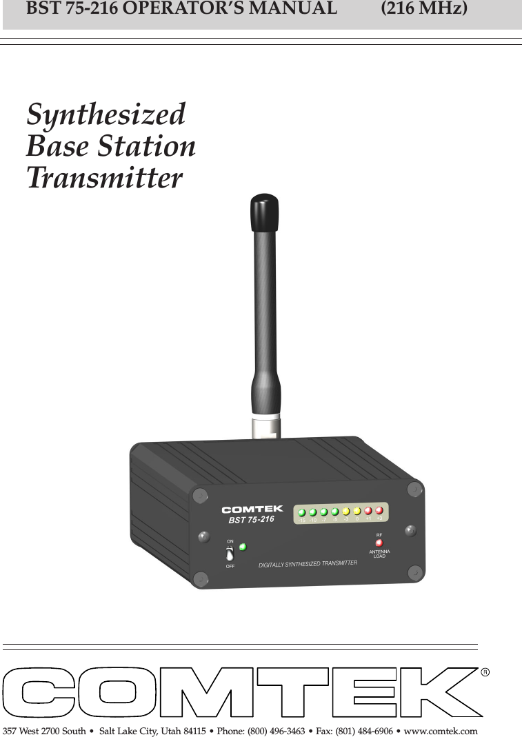
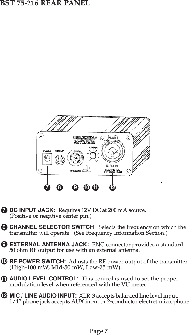
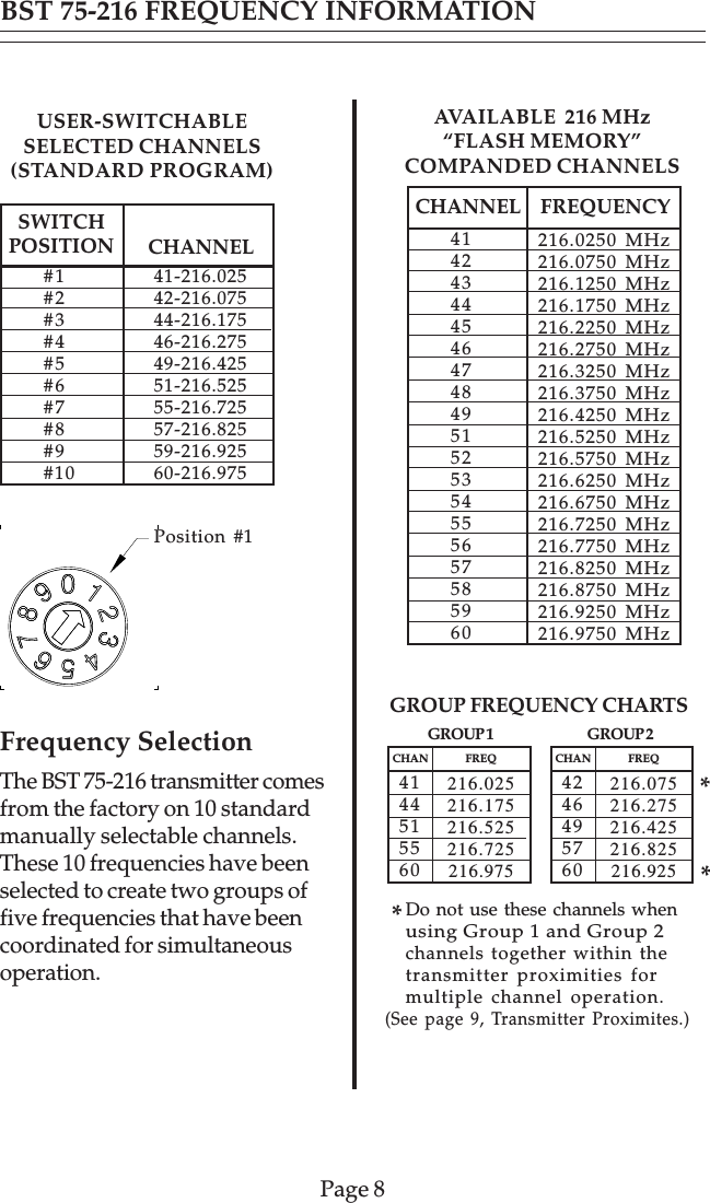
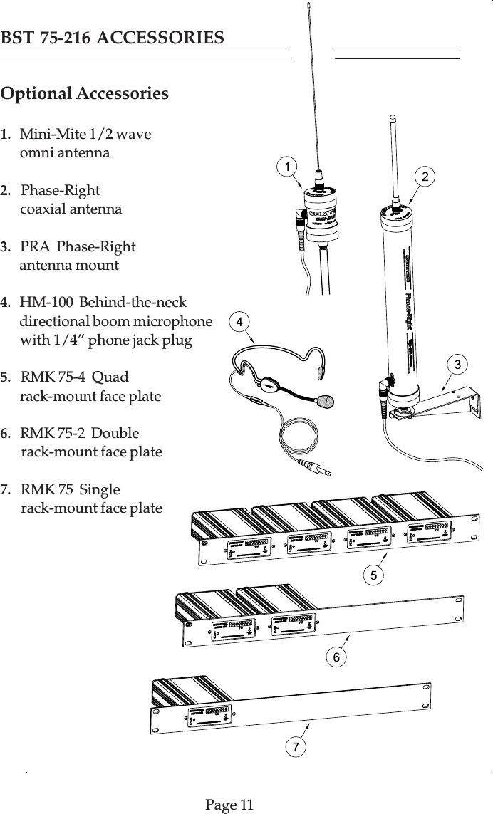
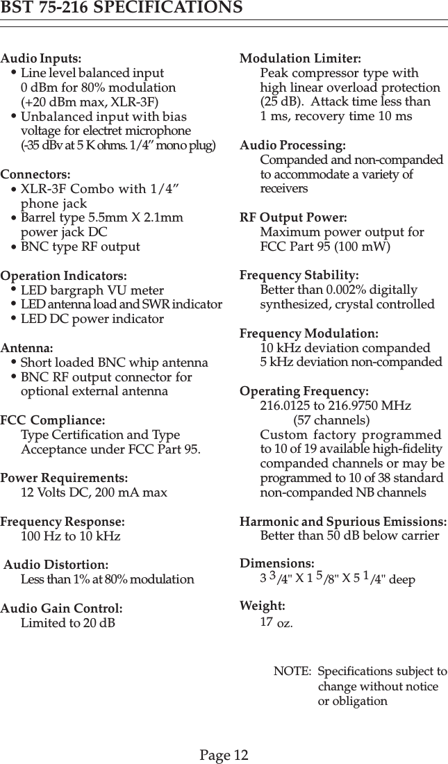
BST 75-216 User's Manual

SynthesizedBase StationTransmitterBST 75-216 OPERATOR’S MANUAL           (216 MHz)357 West 2700 South •  Salt Lake City, Utah 84115 • Phone: (800) 496-3463 • Fax: (801) 484-6906 • www.comtek.com
© 2010 COMTEK® All rights reservedPrinted in U.S.A. 03-10-2010TABLE OF CONTENTSIntroduction  ...........................................................Equipment Placement  ...............................................Power Requirements  .......................................................Remote Antenna  ......................................................Screw-in Whip Antenna  ............................................Audio Input Connections  ...............................................Audio Adjustments  ...............................................Audio Processing Circuit  ..........................................Front and Rear Panel Facilities  ........................................Frequency Information  ..........................................Accessories  ..........................................................Specifications  ......................................................Warranty and Service  ...............................................122334456-78-910-111213NOTE: This equipment has been tested and found to comply with thelimits for a Class A digital device, pursuant to  part 15 of the FCC Rules.These limits are designed to provide reasonable protection againstharmful interference when the equipment is operated in a commercialenvironment.  This equipment generates, uses, and can radiate radiofrequency energy and, if not installed and used in accordance withthe instruction manual, may cause harmful interference to radiocommunications. Operation of this equipment in a residentialarea is likely to cause harmful interference in which case the userwill be required to correct the interference at his own expense.
This transmitter may be used for personal listening applicationssuch as cueing and IFB, wireless automatic tour informationsystems, language interpretation, and for assistive listening forpeople with hearing loss.The BST 75-216 mini base station transmitter meets the highestprofessional standards while offering outstanding value and themost advanced technology available. This versatile and innovativetransmitter is simple to use, yet it has sophisticated features suchas “Flash Memory” 57-channel programmability with a synthesizedmanual 10-channel selectable user-switch.  Plus a unique multi-functionRF indicator detects antenna problems, bad or incorrect antenna, andopen coaxial cable for quick and easy trouble shooting.The audio processing circuit produces full fidelity frequencyresponse from 100 Hz to 10 kHz with very low residual FM noiseand distortion.  To accommodate a greater variety of receivers, theBST  75-216 can operate with non-companded receivers or withcompanded receivers for higher fidelity sound reproduction with asignal-to-noise ratio of up to 90 dB.All this is designed into a stylish, compact, all-metal enclosure suitablefor permanent rack-mount installations or for stand-alone portableapplications.INTRODUCTIONBST 75-216SynthesizedBase StationTransmitterPage 1
Equipment PlacementIf the BST 75-216 base station is to be rack mounted, a remote antennamust be used.  The base station should be mounted away from equipmentthat uses large power transformers to reduce 60 Hz hum possibilities.Special Note:  When using the base station in close proximity to otheraudio equipment, ensure that the audio equipment is not susceptible toRF interference.   This can be accomplished by temporarily installingthe base station as  per above, and then while the base station isoperating, checking all audio outputs for uncharacteristic noise.  If aproblem is found, move the base station or the remote antenna as far aspossible from the affected equipment.  Should you continue to haveproblems, contact COMTEK’s Technical Support Services forassistance.Power RequirementsThe BST 75-216 base station is designed to be powered by 12 volts DC.The standard barrel type power jack (5.5mm X 2.1mm) is nonpolar andwill accept either plus or minus 12 volt DC on thecenter pin.  The switching powersupply adaptor which is includedis a universal input type that willaccept 100-240 volt, 47-63 Hz(AP-12V1B).  The on/off switchon the front panel of the basestation transmitter should beturned to the “off” positionwhen the power plug isinitially plugged into thetransmitter.Page 2OPERATING INSTRUCTIONS
Remote AntennaWhen the BST 75-216 base station transmitteris to be rack mounted for permanentinstallation, a remote antenna must be used.For high performance application whengreater coverage is required, the Phase-Rightor Mini-Mite 1/2 wave omni antenna shouldbe used.  These antennas must be placedvertically polarized up to 15 feet away fromthe transmitter with the coaxial cablesupplied.  The highest possible antennaplacement away from any metallic object isbest.  For high gain directional yagi typeantennas and specialty antennas, contactCOMTEK’s Technical Support Services.Short Loaded Whip BNC AntennaIf the BST 75-216 base station transmitteris to be used outside of the traditionalrack-mounted environment forstand-alone mobile type applications,the short loaded whip antenna(SLW 75-216) should be used.The transmitter should be placedon a table or platform as high aspossible so the antenna is at least24” away from any metallic object.The radiated output power ofthe transmitter with this shortloaded whip antenna will notbe as great as the remoteantennas.  The BST 75-216transmitter should be used onlyin the high power setting whenthe short loaded whip antennais used.Page 3OPERATING INSTRUCTIONSSLW 75-216Phase-Right1/2 WaveMini-Mite
Audio Input ConnectionsThe  BST 75-216 base station transmitter uses an XLR-3F connectorwith a “Combo” phone jack.  The XLR portion of the connector willaccept a true balanced or unbalancedline level signal up to +20 dBm.The 1/4” phone jack portion ofthe connector may be used forAUX output level audio or maydirectly phantom-power mosttwo-conductor electret microphones.Audio AdjustmentsIn order to ensure the highest possible transmission fidelity, thetransmitter must be modulating at least 50% with normal speech(0 dB on the VU meter).  This adjustment is made in the followingmanner:a.  Ensure that the audio source has been optimized for bestsignal-to-noise ratio.b.  The XLR-3 connector located on the back of the transmitter isused for line level balanced or unbalanced audio source (up to +20 dBm).c.  Set the AF Gain Control on the back of the base station  to fullycounterclockwise.  Then, while normal program information is present,slowly rotate the “LEVEL” control clockwise until the VU meter on thefront panel begins to deflect.  Adjustment should be made so thatnormal speech or music deflects the 0 dB yellow LED.  Only peak levelof speech or music should deflect the VU meter full-scale into the lastred LED.Page 4OPERATING INSTRUCTIONS
OPERATING INSTRUCTIONSAudio Processing CircuitThe audio processing system incorporates a peak-level compressor toprevent over-modulation and reduce audio distortion at high levels.This compressor has a very fast attack time and a carefully controlleddecay time to optimize the dynamic performance of the audio processingsystem.  (The VU meter will indicate this compressor action whenthe red LEDs are illuminated.)  The audio is also equalized to addpre-emphasis as well as a very sharp high frequency roll-off circuit tominimize high frequency noise in the audio signal.  The total frequencyresponse and performance of the system is, however, determined by thecorresponding de-emphasis and equalization used in the receiver.In order to accommodate a greater variety of receivers, the BST 75-216transmitter incorporates the option to operate with receiversthat have companded or non-companded audio processing.However, the BST 75-216 transmitter must operate non-compandedwith non-companded receivers and companded only with receiversthat incorporate companding processing.  A mismatch will result inunacceptable audio performance.Basic Companding TheoryThe dynamic range of the audio signal is compressed in the transmitterat a 2:1 ratio.  The receiver then expands the audio signal at acomplementary 1:2 ratio to restore the dynamic range of the audio signalto the original level and also to provide additional noise reductionwhen no audio signal is present.Page 5
OPTIONAL ANTENNA:  Used for mobile type applications.POWER SWITCH:  Turns the transmitter on or off.POWER LED INDICATOR:  Illuminates when the power is on.VU METER:  Displays the audio level being used for modulation.(See Audio Adjustment Section.)ANTENNA INDICATOR:  Detects antenna problems: bad, or incorrectantenna, and open coaxial cable.RACK-MOUNTING SCREWS:  Used for mounting BST 75-216 torack-mounting panels.BST 75-216 FRONT PANELPage 643213 5426516
1278910BST 75-216 REAR PANELDC INPUT JACK:  Requires 12V DC at 200 mA source.(Positive or negative center pin.)CHANNEL SELECTOR SWITCH:  Selects the frequency on which thetransmitter will operate.  (See Frequency Information Section.)EXTERNAL ANTENNA JACK:  BNC connector provides a standard50 ohm RF output for use with an external antenna.RF POWER SWITCH:  Adjusts the RF power output of the transmitter(High-100 mW, Mid-50 mW, Low-25 mW).AUDIO LEVEL CONTROL:  This control is used to set the propermodulation level when referenced with the VU meter.MIC / LINE AUDIO INPUT:  XLR-3 accepts balanced line level input.1/4” phone jack accepts AUX input or 2-conductor electret microphone.11Page 7710912811
*Page 8SWITCHPOSITION CHANNEL#1#2#3#4#5#6#7#8#9#10   41-216.025   42-216.075   44-216.175   46-216.275   49-216.425   51-216.525   55-216.725   57-216.825   59-216.925   60-216.975USER-SWITCHABLESELECTED CHANNELS(STANDARD PROGRAM)AVAILABLE  216 MHz“FLASH MEMORY”COMPANDED CHANNELSBST 75-216 FREQUENCY INFORMATIONGROUP 1CHAN          FREQ216.025216.175216.525216.725216.9754144515560GROUP FREQUENCY CHARTSCHANNEL FREQUENCY41424344454647484951525354555657585960216.0250 MHz216.0750 MHz216.1250 MHz216.1750 MHz216.2250 MHz216.2750 MHz216.3250 MHz216.3750 MHz216.4250 MHz216.5250 MHz216.5750 MHz216.6250 MHz216.6750 MHz216.7250 MHz216.7750 MHz216.8250 MHz216.8750 MHz216.9250 MHz216.9750 MHzPosition #1Frequency SelectionThe BST 75-216 transmitter comesfrom the factory on 10 standardmanually selectable channels.These 10 frequencies have beenselected to create two groups offive frequencies that have beencoordinated for simultaneousoperation.GROUP 2CHAN          FREQ216.075216.275216.425216.825216.9254246495760Do not use these channels whenusing Group 1 and Group 2channels together within thetransmitter proximities formultiple channel operation.(See page 9, Transmitter Proximites.)**
Page 9Multiple Channel OperationWhen multiple transmitters (more than two) are used in the sameproximity,  intermodulation interference can occur.  This conditionis common to all radio receivers to some extent when multipletransmitters are used in the same operating area.  The RF signals will“MIX” together generating additional signals.  If these productfrequencies are too close to a frequency which the receiver can alsorespond to, you will experience intermodulation interference whichmay cause undesirable operation.To avoid this type of interference when multiple transmitters are usedin the same proximity, transmitting frequencies must be coordinatedby selecting from frequencies in the same group.(See group frequency chart on page 8.)Transmitter Proximities ForMultiple ChannelOperationFrequency groups beingtransmitted should beseparated by 2X theoperating area; and forbest performance, thegroup operating areasshould have a 100 ft.minimum separation.Free Frequency Coordination SoftwareFrequency coordination and after-sale programming for differentcompatible frequency groups can be done through COMTEK’sTechnical Support Services.  Frequency selection software may bedownloaded from COMTEK’s website at www.comtek/support.htmlBST 75-216 FREQUENCY INFORMATIONtransmitterstransmittersGroup 1operating area Group 2operating areaTransmitterseparation
Page 10BST 75-216 ACCESSORIESIncluded Accessories1.   C-75  Carrying case2.   BST-75  Operator’s manual3.   SLW 75-216 Short loaded      whip antenna4.   AP-12VAC  Power adaptor      (115V AC Input)5.   BST-75  Base station transmitter
BST 75-216 ACCESSORIESPage 11Optional Accessories1.   Mini-Mite 1/2 wave      omni antenna2.   Phase-Right      coaxial antenna3.   PRA  Phase-Right      antenna mount4.   HM-100  Behind-the-neck       directional boom microphone      with 1/4” phone jack plug5.   RMK 75-4  Quad       rack-mount face plate6.   RMK 75-2  Double       rack-mount face plate7.   RMK 75  Single       rack-mount face plate
Page 12Audio Inputs:Line level balanced input0 dBm for 80% modulation(+20 dBm max, XLR-3F)Unbalanced input with biasvoltage for electret microphone(-35 dBv at 5 K ohms. 1/4” mono plug)Connectors:XLR-3F Combo with 1/4”phone jackBarrel type 5.5mm X 2.1mmpower jack DCBNC type RF outputOperation Indicators:LED bargraph VU meterLED antenna load and SWR indicatorLED DC power indicatorAntenna:Short loaded BNC whip antennaBNC RF output connector foroptional external antennaFCC Compliance:Type Certification and TypeAcceptance under FCC Part 95.Power Requirements:12 Volts DC, 200 mA maxFrequency Response:100 Hz to 10 kHz Audio Distortion:Less than 1% at 80% modulationAudio Gain Control:Limited to 20 dBModulation Limiter:Peak compressor type withhigh linear overload protection(25 dB).  Attack time less than1 ms, recovery time 10 msAudio Processing:Companded and non-compandedto accommodate a variety ofreceiversRF Output Power:Maximum power output forFCC Part 95 (100 mW)Frequency Stability:Better than 0.002% digitallysynthesized, crystal controlledFrequency Modulation:10 kHz deviation companded5 kHz deviation non-compandedOperating Frequency:216.0125 to 216.9750 MHz          (57 channels)Custom factory programmedto 10 of 19 available high-fidelitycompanded channels or may beprogrammed to 10 of 38 standardnon-companded NB channelsHarmonic and Spurious Emissions:Better than 50 dB below carrierDimensions:3 3/4" X 1 5/8" X 5 1/4" deepWeight:17 oz.BST 75-216 SPECIFICATIONS•••••••NOTE:  Specifications subject to               change without notice               or obligation•••
WARRANTY AND SERVICEWarrantyCOMTEK transmitters and receivers are warranted to be free from defects inworkmanship and material under normal stand-alone use and conditions fora period of two years from date of original purchase.  Items such asheadphones and earphones, neckloops, and cords are warranted to befree from defects in workmanship and material for a period of 90 days fromthe date of original purchase.  Batteries are not covered by this warranty.Damage due to abnormal use, extreme conditions, misuse, use of the productas a component of another product, ill treatment and unauthorizedmodification and repairs are not covered by this warranty.  COMTEK is notliable for any consequential or punitive damages arising out of any failureof the equipment to perform as intended.  COMTEK shall bear noresponsibility or obligation with respect to the manner of use of anyequipment sold by it.  COMTEK SPECIFICALLY DISCLAIMS ANDNEGATES ANY WARRANTY OF MERCHANTABILITY OR FITNESSOF THE PRODUCT FOR A PARTICULAR PURPOSE INCLUDING,WITHOUT LIMITATION, ANY WARRANTY THAT THE USE OF SUCHEQUIPMENT FOR ANY PURPOSE WILL COMPLY WITH APPLICABLELAWS AND REGULATIONS.Service PoliciesWarranty repairs must be done by COMTEK.  Only factory technicians areauthorized to perform warranty service on the BST 75-216 transmitter. Beforereturning the BST 75-216 for service, a Return Authorization Number shouldbe obtained from the service department by calling 1-800-496-3463 or1-801-466-3463. Return the unit to the factory with the original or comparablepacking.  COMTEK will pay for insurance and ground return shipping costs inthe United States for all warranty service.357 West 2700 South •  Salt Lake City, Utah 84115 • Phone: (800) 496-3463 • Fax: (801) 484-6906 • www.comtek.comE-mail:  sales@comtek.com
357 West 2700 South •  Salt Lake City, Utah 84115 • Phone: (800) 496-3463 • Fax: (801) 484-6906 • www.comtek.com

Navigation menu