Comtek Communications Technology M175 Personal body-worn communication transmitter User Manual C 175rpt tableofcontent wpd
Comtek Communications Technology Inc Personal body-worn communication transmitter C 175rpt tableofcontent wpd
UserManual.wiki
>
Comtek Communications Technology
>
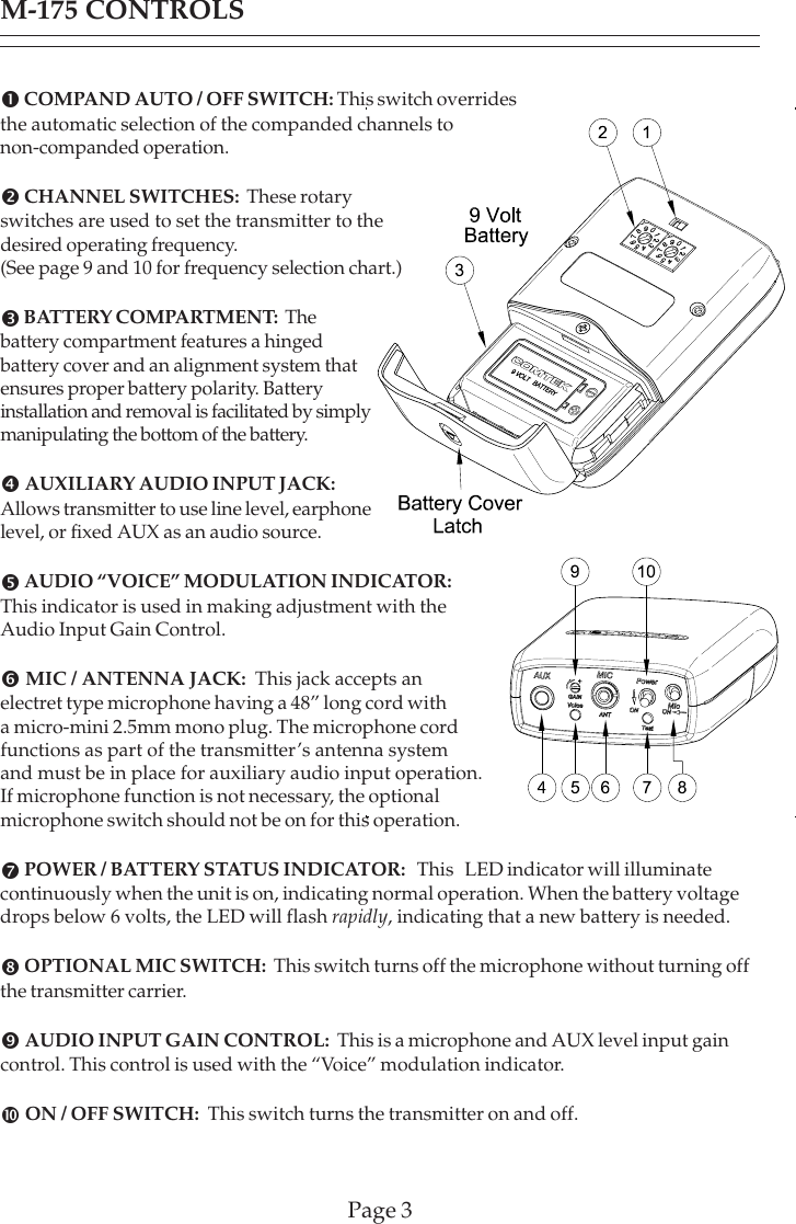
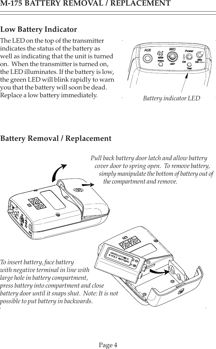
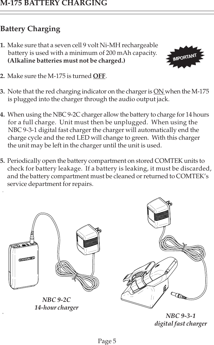
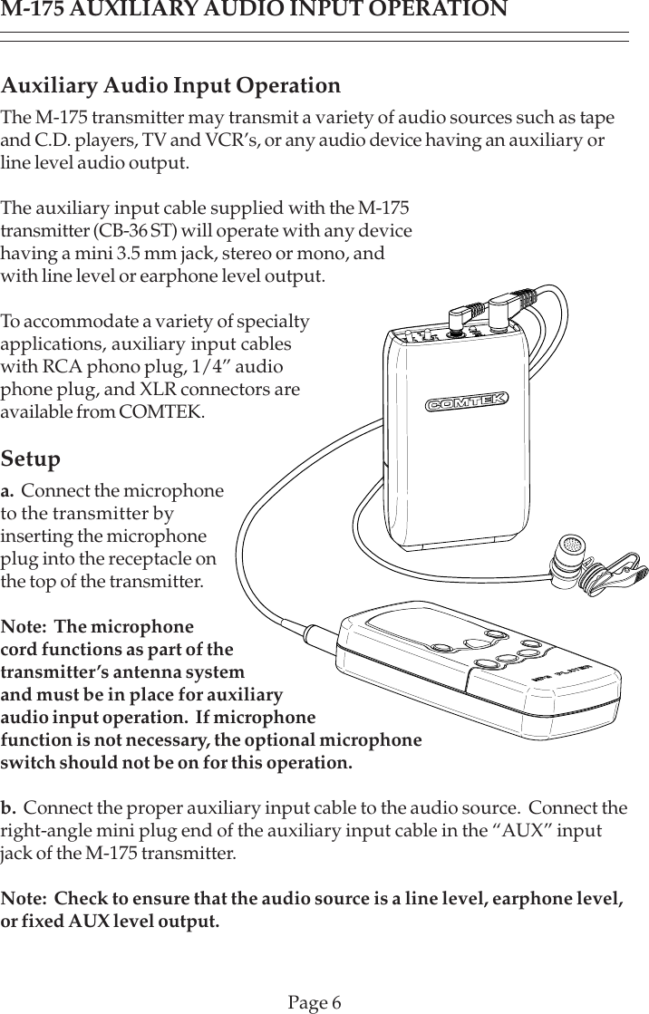
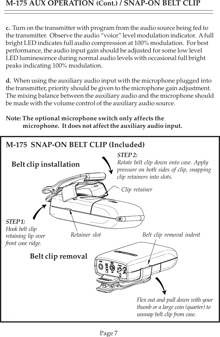
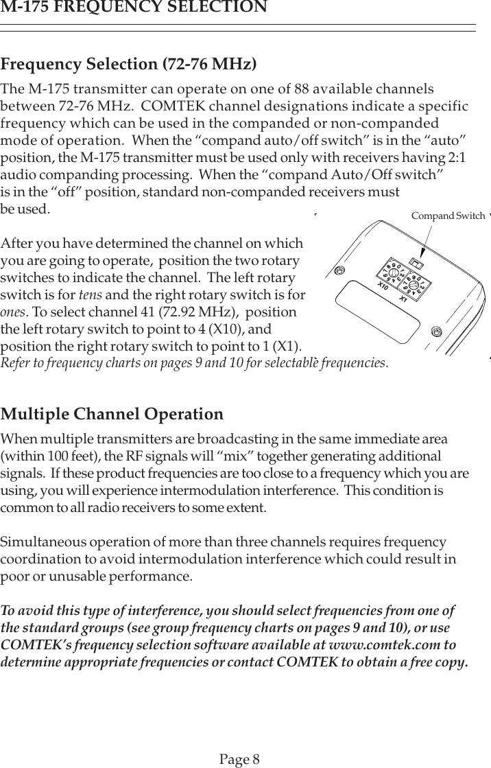
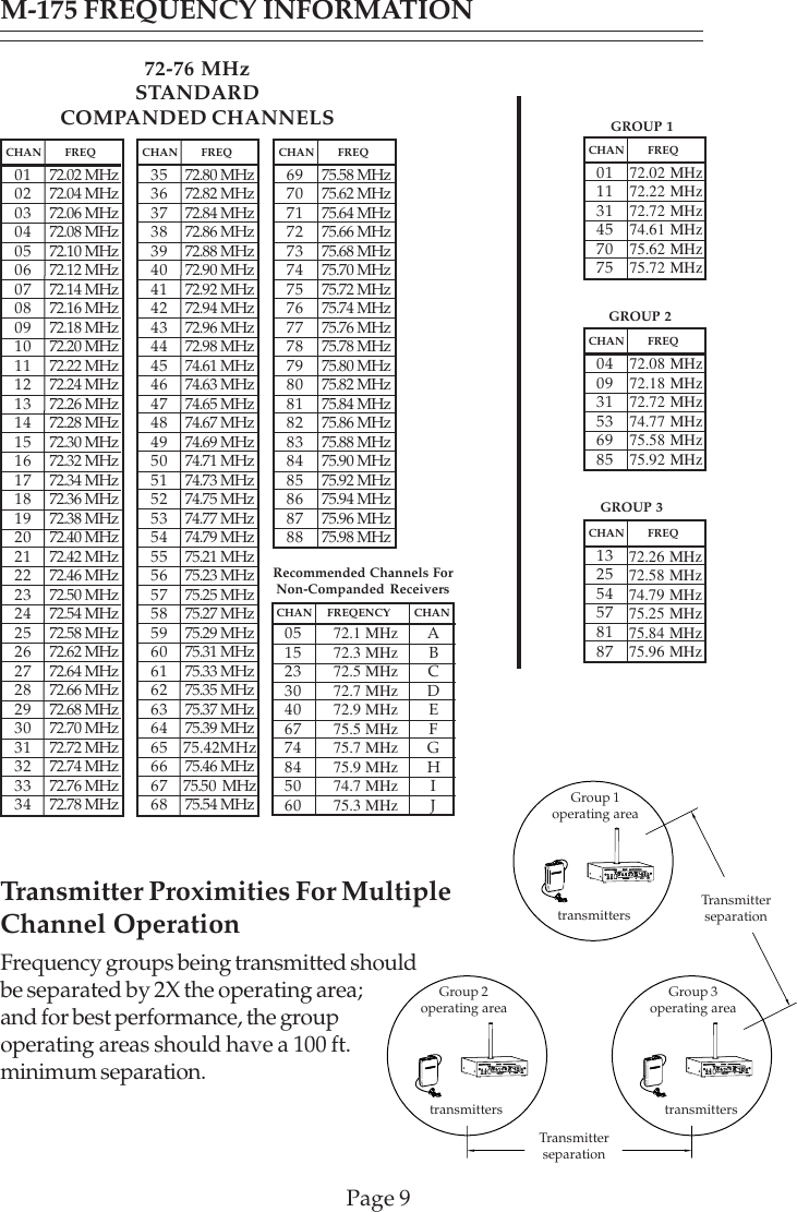
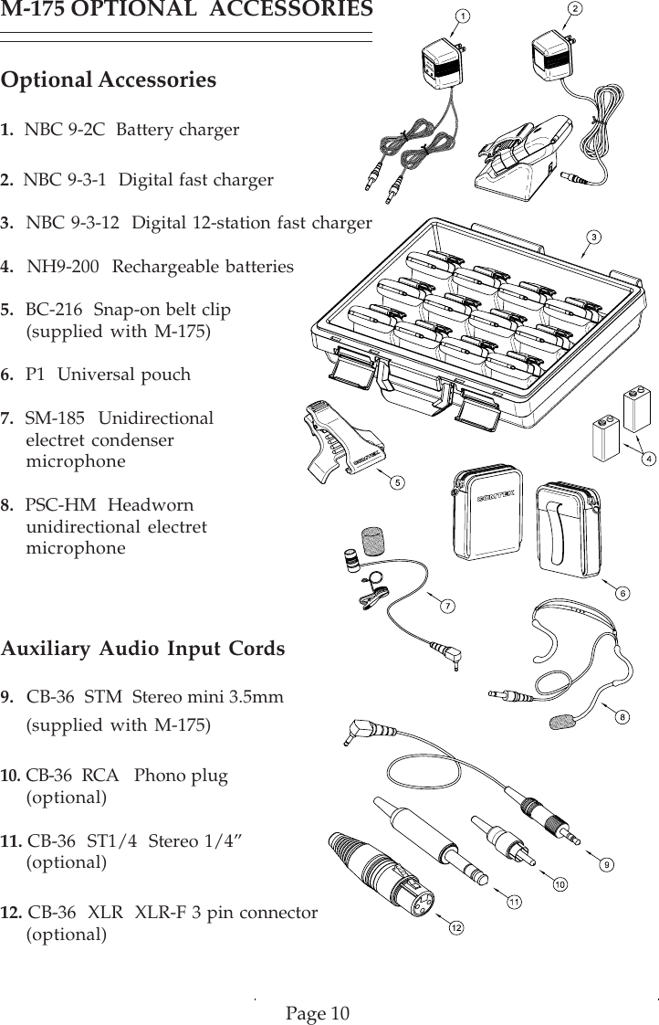
M175 User Manual
User Manual
Navigation menu
Upload a User Manual
Namespaces
Wiki Guide
HTML
PDF
Info
Views
User Manual
Discussion / Help
Navigation