Comtek Communications Technology M216 Wireless Microphone Transmitter User Manual C 216rpt exhibitpages wpd
Comtek Communications Technology Inc Wireless Microphone Transmitter C 216rpt exhibitpages wpd
UserManual.wiki
>
Comtek Communications Technology
>
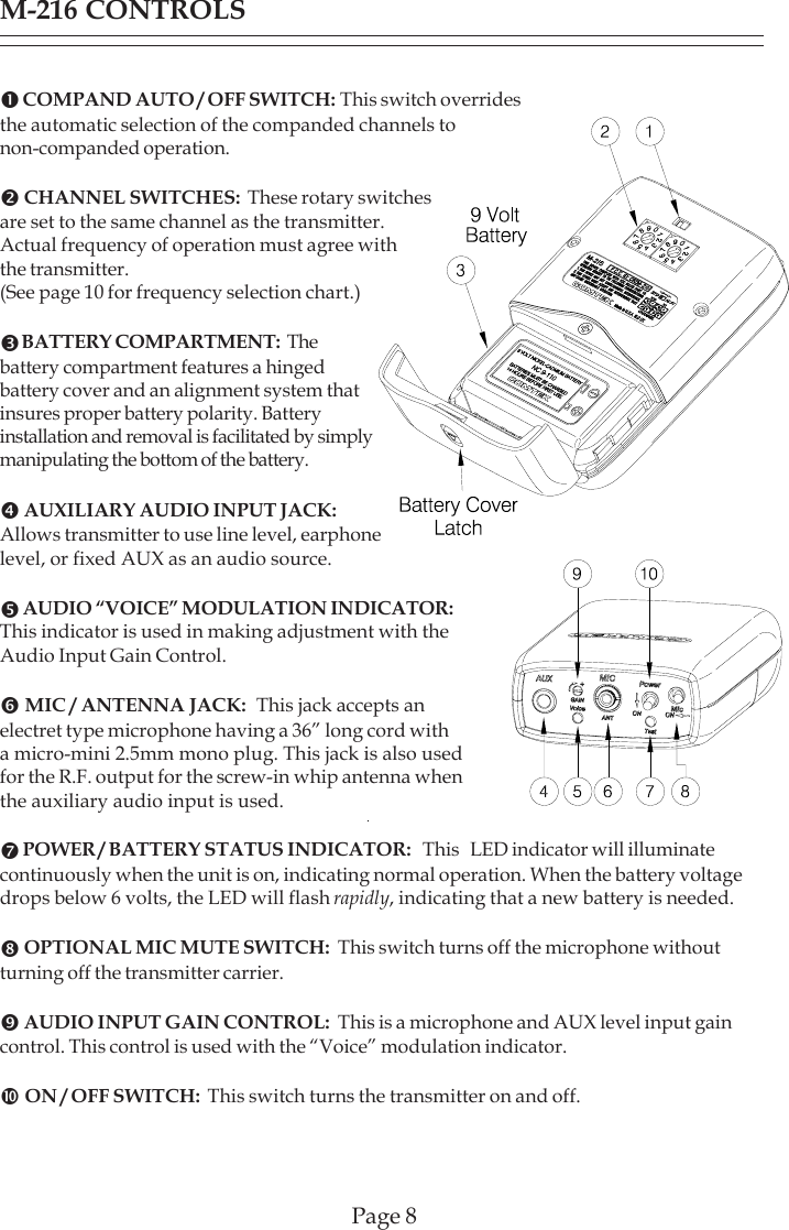
M216 User Manual
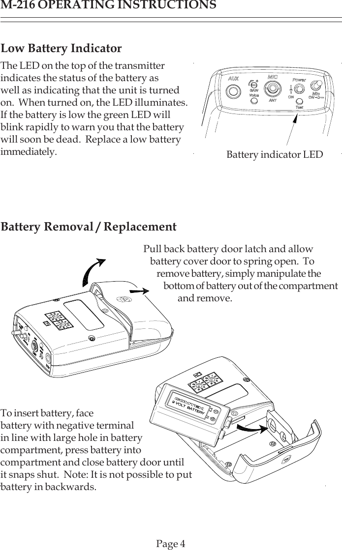
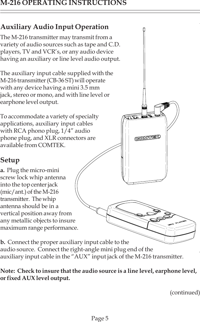
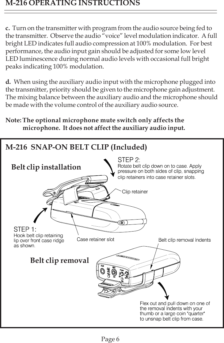
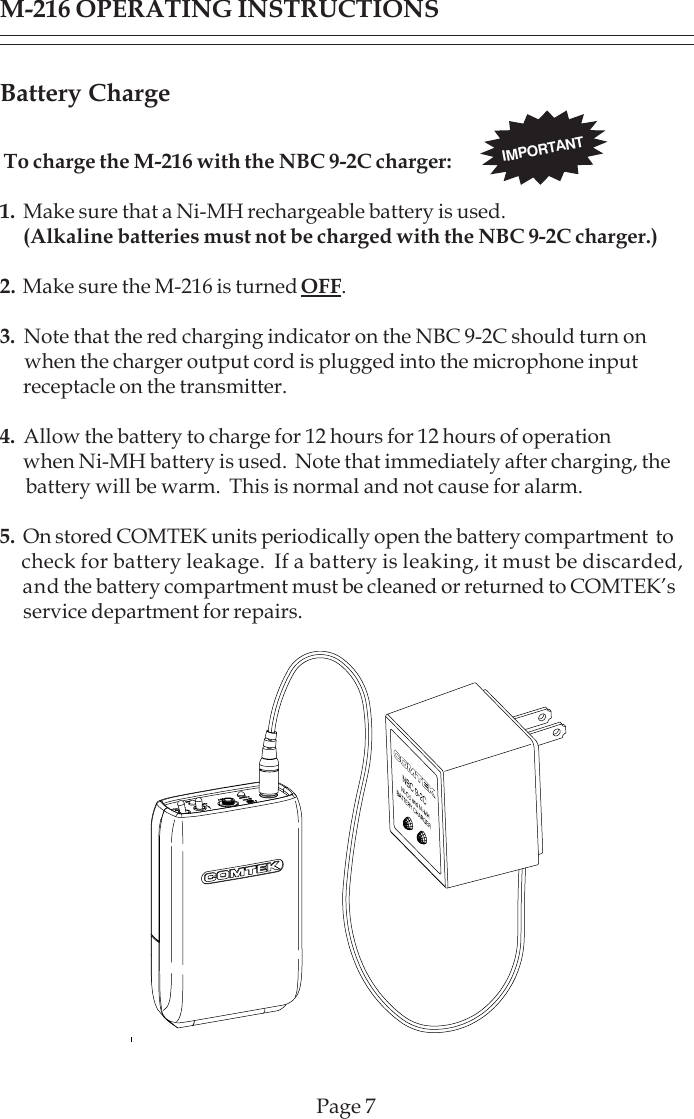
Operations Manual
Navigation menu
Upload a User Manual
Namespaces
Wiki Guide
HTML
PDF
Info
Views
User Manual
Discussion / Help
Navigation