Comtrend 5700 Wireless ADSL IAD User Manual UM NexusLink 5700 C1 0
Comtrend Corporation Wireless ADSL IAD UM NexusLink 5700 C1 0
UserManual.wiki
>
Comtrend
>
5700 User Manual
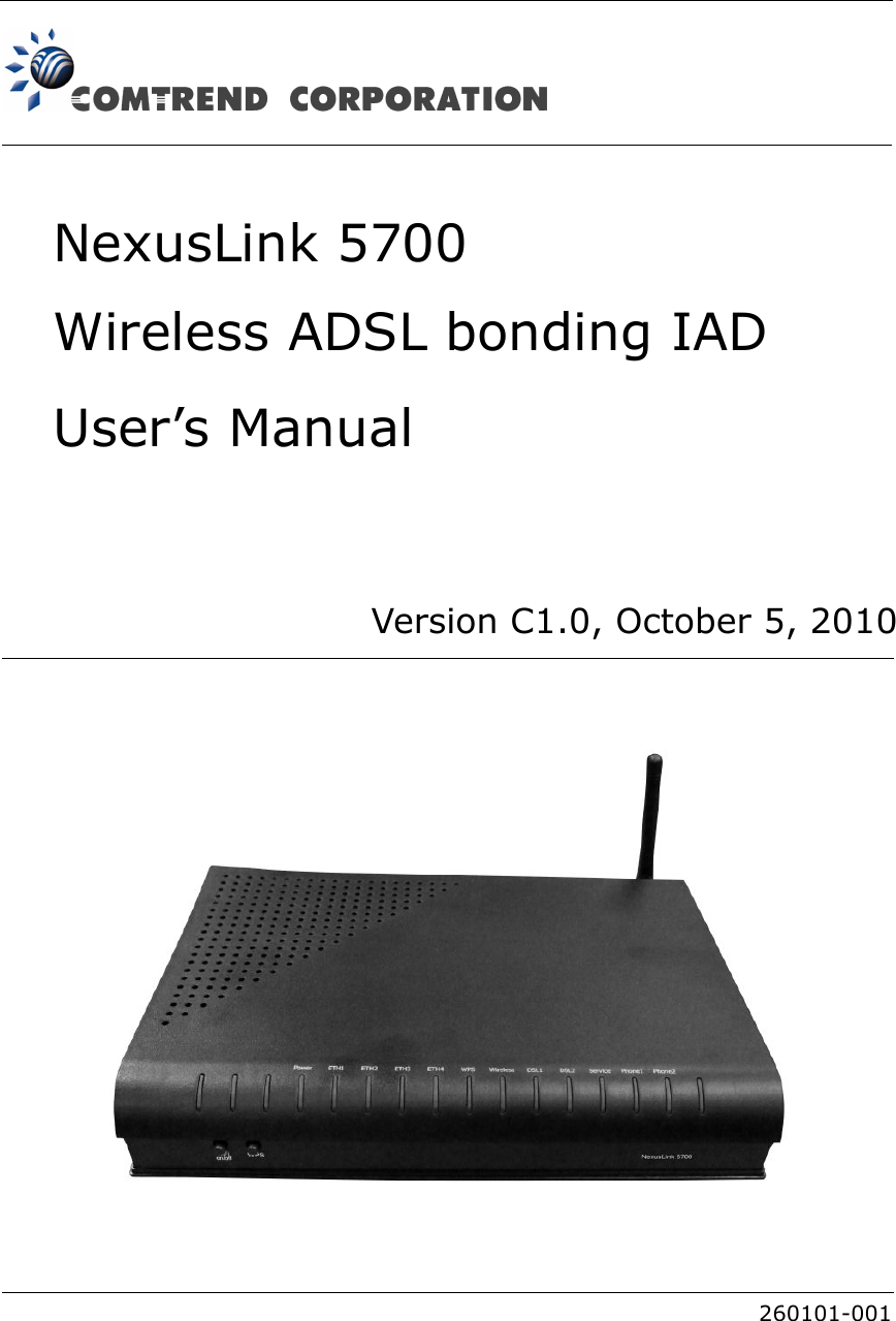
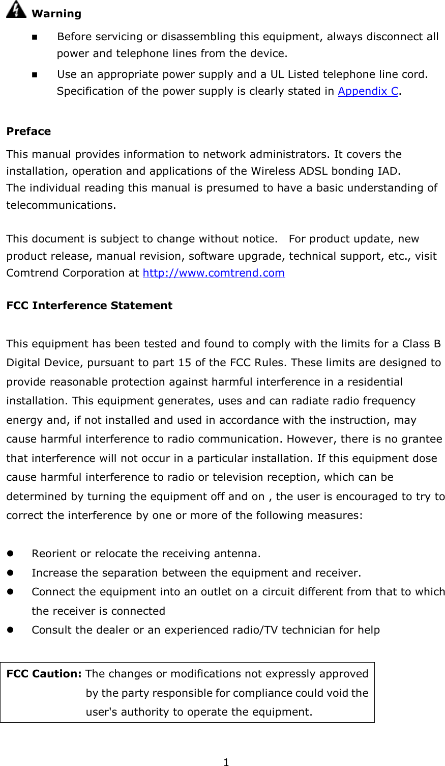
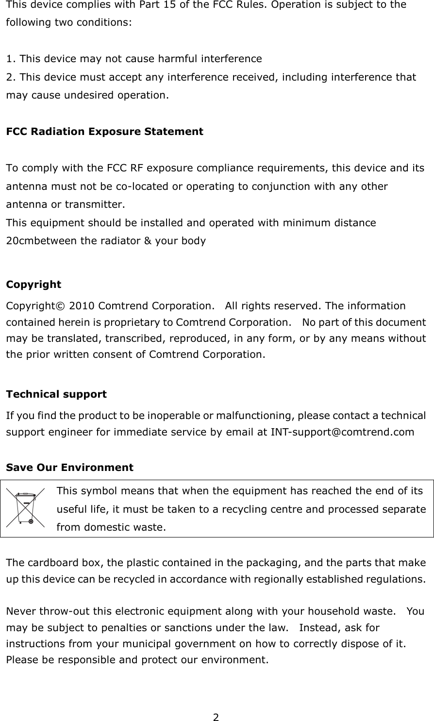
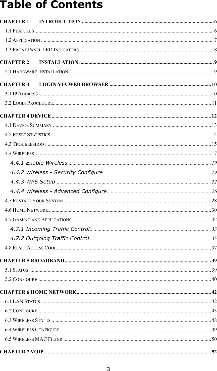
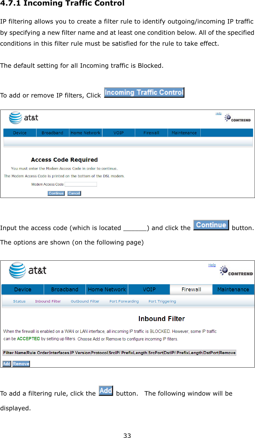
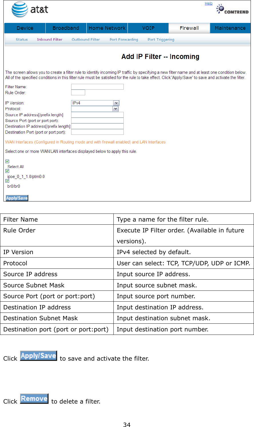
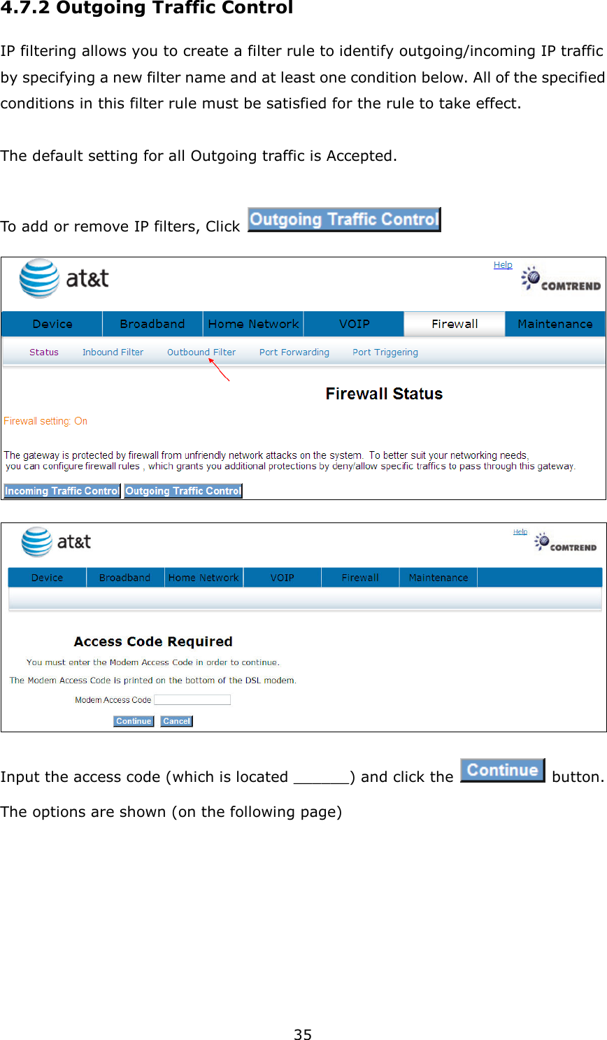
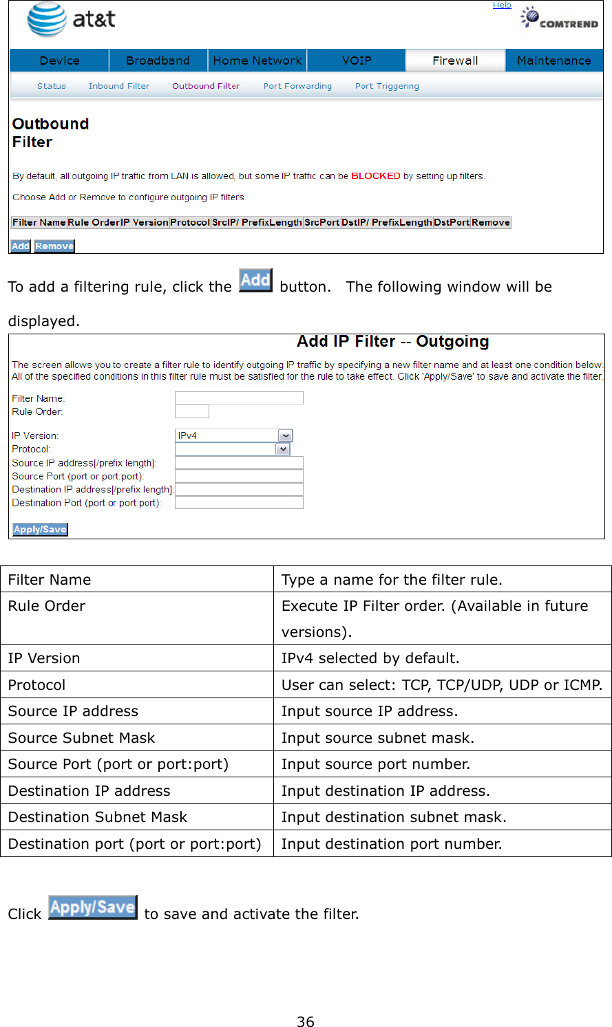
5.User's manual
Navigation menu
Upload a User Manual
Namespaces
Wiki Guide
HTML
PDF
Info
Views
User Manual
Discussion / Help
Navigation