Comtrend AR-5312U A/VDSL Bonded Router User Manual UM AR5312u A1 0 FCC
Comtrend Corporation A/VDSL Bonded Router UM AR5312u A1 0 FCC
Comtrend >
Contents
- 1. 5.User manual-1
- 2. 5.User manual-2
5.User manual-2
87
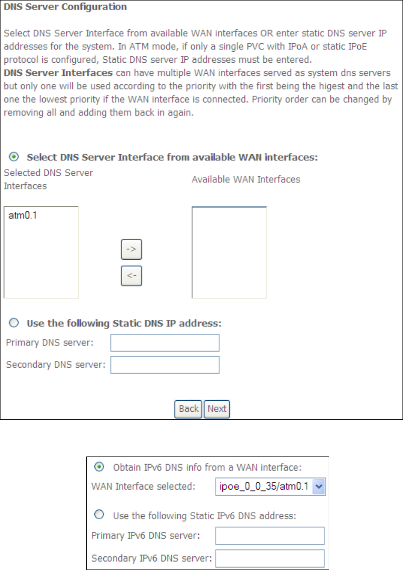
6.5 DNS
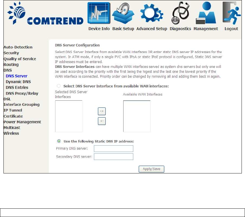
6.5.1 DNS Server
Select DNS Server Interface from available WAN interfaces OR enter static DNS
server IP addresses for the system. In ATM mode, if only a single PVC with IPoA or
static IPoE protocol is configured, Static DNS server IP addresses must be entered.
DNS Server Interfaces can have multiple WAN interfaces served as system dns
servers but only one will be used according to the priority with the first being the
highest and the last one the lowest priority if the WAN interface is connected.
Priority order can be changed by removing all and adding them back in again.
Click Apply/Save to save the new configuration.
NOTE: You must reboot the router to make the new configuration effective.
88
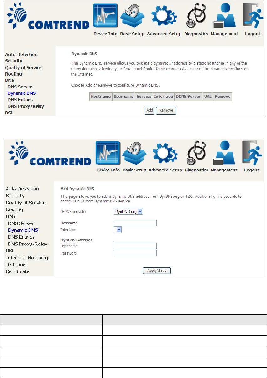
6.5.2 Dynamic DNS
The Dynamic DNS service allows you to map a dynamic IP address to a static
hostname in any of many domains, allowing the AR-5312u to be more easily
accessed from various locations on the Internet.
To add a dynamic DNS service, click Add. The following screen will display.
Click Apply/Save to save your settings.
Consult the table below for field descriptions.
Field Description
D-DNS provider Select a dynamic DNS provider from the list
Hostname Enter the name of the dynamic DNS server
Interface Select the interface from the list
Username Enter the username of the dynamic DNS server
Password Enter the password of the dynamic DNS server
89
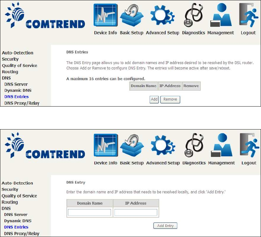
6.5.3 DNS Entries
The DNS Entry page allows you to add domain names and IP address desired to be
resolved by the DSL router.
Choose Add or Remove to configure DNS Entry. The entries will become active after
save/reboot.
Enter the domain name and IP address that needs to be resolved locally, and click
the Add Entry button.
90
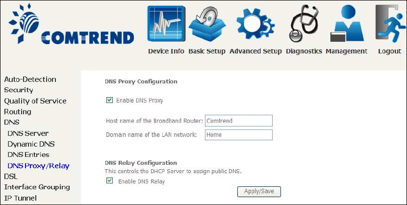
6.5.4 DNS Proxy/Relay
DNS proxy receives DNS queries and forwards DNS queries to the Internet. After the
CPE gets answers from the DNS server, it replies to the LAN clients. Configure DNS
proxy with the default setting, when the PC gets an IP via DHCP, the domain name,
Home, will be added to PC’s DNS Suffix Search List, and the PC can access route with
“Comtrend.Home”.
91
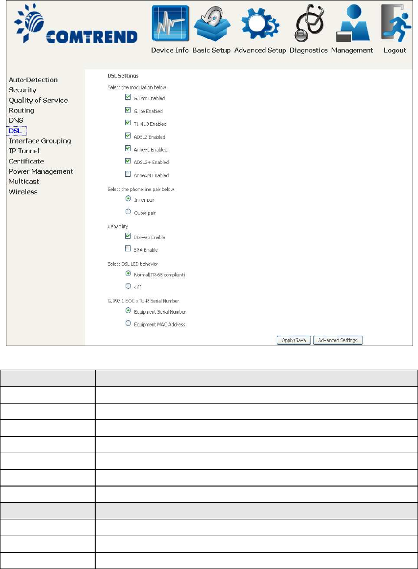
6.6 DSL
The DSL Settings screen allows for the selection of DSL modulation modes.
For optimum performance, the modes selected should match those of your ISP.
DSL Mode Data Transmission Rate - Mbps (Megabits per second)
G.Dmt Downstream: 12 Mbps Upstream: 1.3 Mbps
G.lite Downstream: 4 Mbps Upstream: 0.5 Mbps
T1.413 Downstream: 8 Mbps Upstream: 1.0 Mbps
ADSL2 Downstream: 12 Mbps Upstream: 1.0 Mbps
AnnexL Supports longer loops but with reduced transmission rates
ADSL2+ Downstream: 24 Mbps Upstream: 1.0 Mbps
AnnexM Downstream: 24 Mbps Upstream: 3.5 Mbps
Options Description
Inner/Outer Pair Select the inner or outer pins of the twisted pair (RJ11 cable)
Bitswap Enable Enables adaptive handshaking functionality
SRA Enable Enables Seamless Rate Adaptation (SRA)
92
DSL Mode Data Transmission Rate - Mbps (Megabits per second)
Select DSL LED
behavior
Normal (TR-68 compliant): Select this option for DSL LED to
operate normally (See menu 2.2 LED Indicator)
Off:DSL LED will always be OFF
G997.1 EOC
xTU-R Serial
Number
Select Equipment Serial Number or Equipment MAC Address to
use router’s serial number or MAC address in ADSL EOC
messages
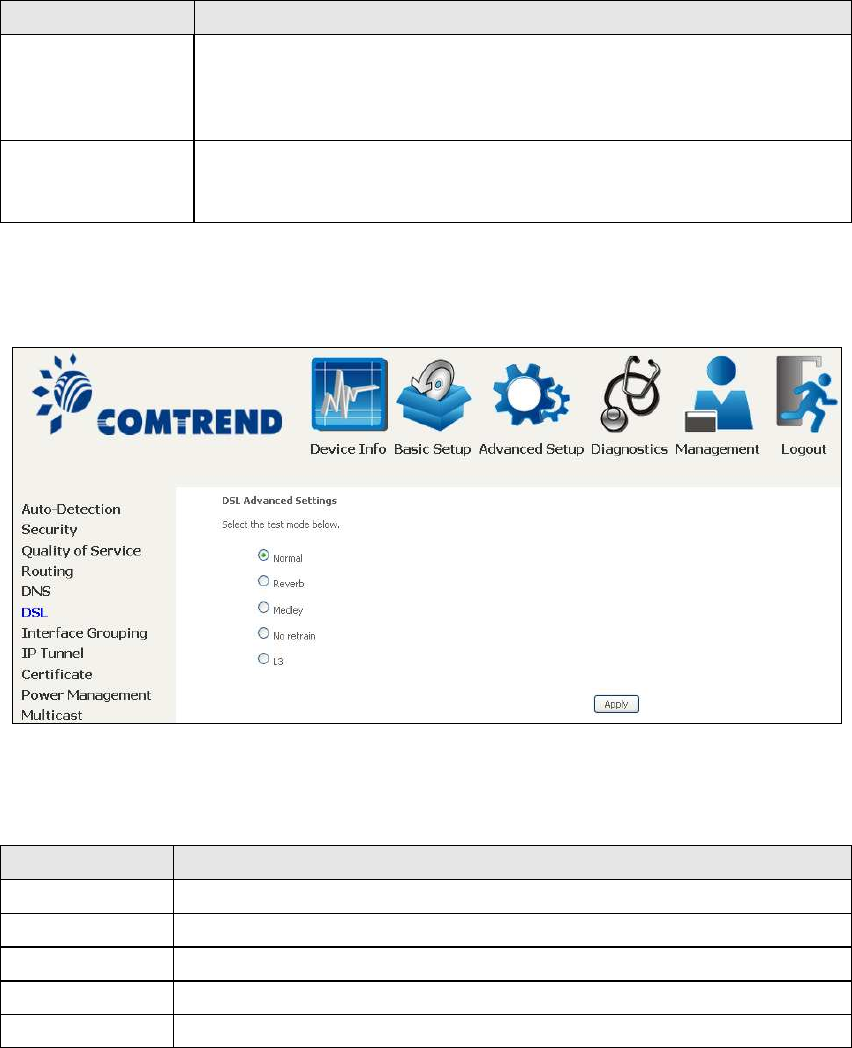
Advanced DSL Settings
Click Advanced Settings to reveal additional options.
On this screen you select the required test mode, then click the Apply button.
Field Description
Normal DSL line signal is detected and sent normally
Reverb DSL line signal is sent continuously in reverb mode
Medley DSL line signal is sent continuously in medley mode
No Retrain DSL line signal will always be on even when DSL line is unplugged
L3 DSL line is set in L3 power mode
93
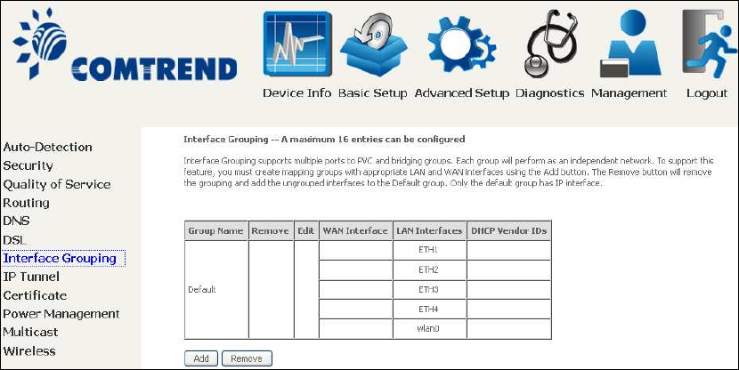
6.7 Interface Grouping
Interface Grouping supports multiple ports to PVC and bridging groups. Each group
performs as an independent network. To use this feature, you must create mapping
groups with appropriate LAN and WAN interfaces using the Add button.
The Remove button removes mapping groups, returning the ungrouped interfaces
to the Default group. Only the default group has an IP interface.
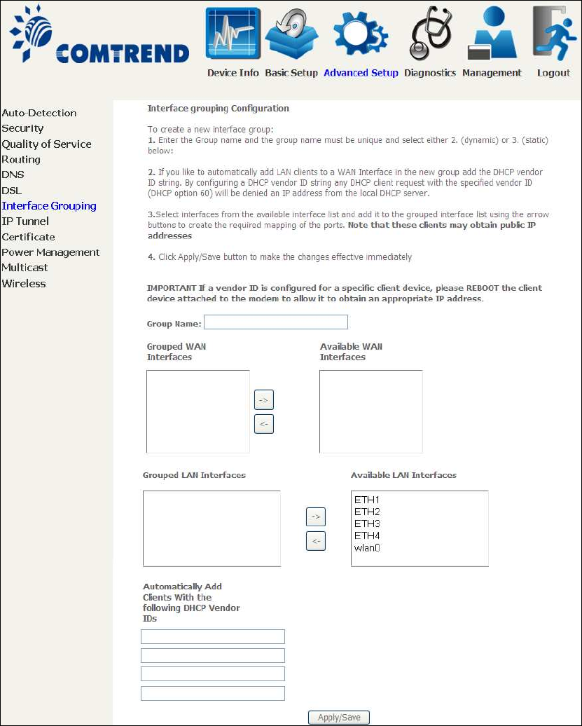
To add an Interface Group, click the Add button. The following screen will appear.
It lists the available and grouped interfaces. Follow the instructions shown
onscreen.
94
Automatically Add Clients With Following DHCP Vendor IDs:
Add support to automatically map LAN interfaces to PVC's using DHCP vendor ID
(option 60). The local DHCP server will decline and send the requests to a remote
DHCP server by mapping the appropriate LAN interface. This will be turned on when
Interface Grouping is enabled.
For example, imagine there are 4 PVCs (0/33, 0/36, 0/37, 0/38). VPI/VCI=0/33 is
for PPPoE while the other PVCs are for IP set-top box (video). The LAN interfaces are
ETH1, ETH2, ETH3, and ETH4.
The Interface Grouping configuration will be:
95
1. Default: ETH1, ETH2, ETH3, and ETH4.
2. Video: nas_0_36, nas_0_37, and nas_0_38. The DHCP vendor ID is "Video".
If the onboard DHCP server is running on "Default" and the remote DHCP server is
running on PVC 0/36 (i.e. for set-top box use only). LAN side clients can get IP
addresses from the CPE's DHCP server and access the Internet via PPPoE (0/33).
If a set-top box is connected to ETH1 and sends a DHCP request with vendor ID
"Video", the local DHCP server will forward this request to the remote DHCP server.
The Interface Grouping configuration will automatically change to the following:
1. Default: ETH2, ETH3, and ETH4
2. Video: nas_0_36, nas_0_37, nas_0_38, and ETH1
96
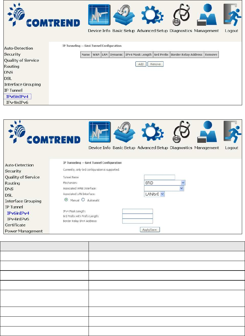
6.8 IP Tunnel
6.8.1 IPv6inIPv4
Configure 6in4 tunneling to encapsulate IPv6 traffic over explicitly-configured IPv4
links.
Click the Add button to display the following.
Options Description
Tunnel Name Input a name for the tunnel
Mechanism Mechanism used by the tunnel deployment
Associated WAN Interface Select the WAN interface to be used by the tunnel
Associated LAN Interface Select the LAN interface to be included in the tunnel
Manual/Automatic Select automatic for point-to-multipoint tunneling /
manual for point-to-point tunneling
IPv4 Mask Length The subnet mask length used for the IPv4 interface
6rd Prefix with Prefix Length Prefix and prefix length used for the IPv6 interface
Border Relay IPv4 Address
Input the IPv4 address of the other device
97
6.8.2 IPv4inIPv6
ġ
ġġġ
Configure 4in6 tunneling to encapsulate IPv4 traffic over an IPv6-only environment.
Click the Add button to display the following.
Options Description
Tunnel Name Input a name for the tunnel
Mechanism Mechanism used by the tunnel deployment
Associated WAN Interface Select the WAN interface to be used by the tunnel
Associated LAN Interface Select the LAN interface to be included in the tunnel
Manual/Automatic Select automatic for point-to-multipoint tunneling /
manual for point-to-point tunneling
AFTR Address of Address Family Translation Router
98
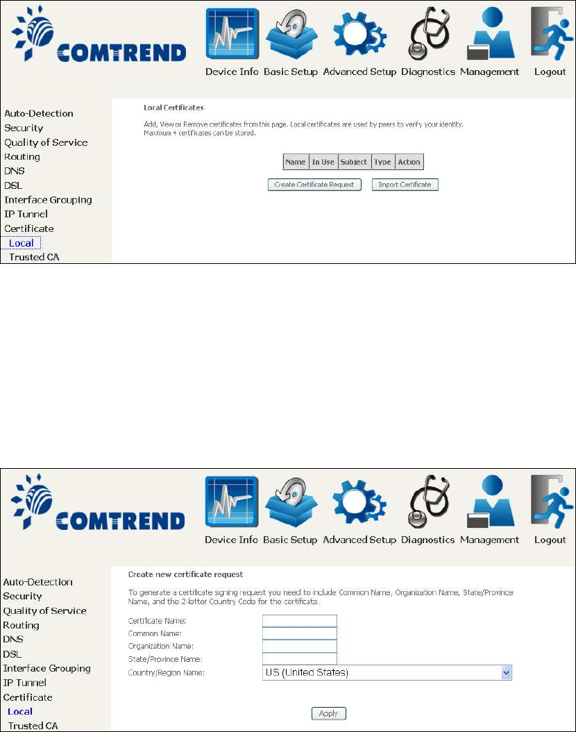
6.9 Certificate
A certificate is a public key, attached with its owner’s information (company name,
server name, personal real name, contact e-mail, postal address, etc) and digital
signatures. There will be one or more digital signatures attached to the certificate,
indicating that these entities have verified that this certificate is valid.
6.9.1 Local
CREATE CERTIFICATE REQUEST
Click Create Certificate Request to generate a certificate-signing request.
The certificate-signing request can be submitted to the vendor/ISP/ITSP to apply for
a certificate. Some information must be included in the certificate-signing request.
Your vendor/ISP/ITSP will ask you to provide the information they require and to
provide the information in the format they regulate. Enter the required information
and click Apply to generate a private key and a certificate-signing request.
The following table is provided for your reference.
99
Field Description
Certificate Name A user-defined name for the certificate.
Common Name Usually, the fully qualified domain name for the machine.
Organization Name The exact legal name of your organization.
Do not abbreviate.
State/Province Name
T
he state or province where your or
g
anization is located.
It cannot be abbreviated.
Country/Region Name The two-letter ISO abbreviation for your country.
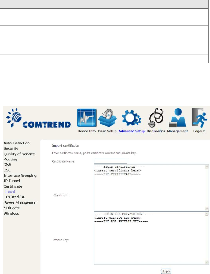
IMPORT CERTIFICATE
Click Import Certificate to paste the certificate content and the private key
provided by your vendor/ISP/ITSP into the corresponding boxes shown below.
Enter a certificate name and click the Apply button to import the certificate and its
private key.
100
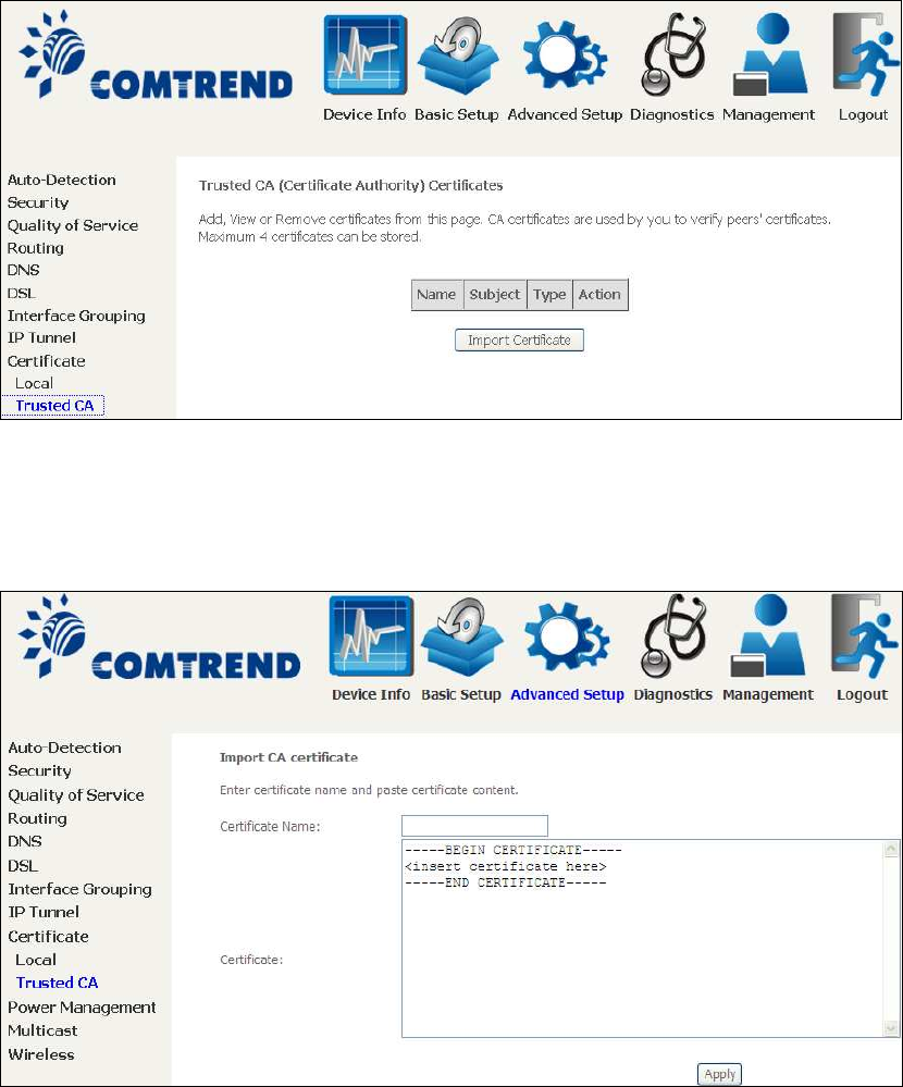
6.9.2 Trusted CA
CA is an abbreviation for Certificate Authority, which is a part of the X.509 system.
It is itself a certificate, attached with the owner information of this certificate
authority; but its purpose is not encryption/decryption. Its purpose is to sign and
issue certificates, in order to prove that these certificates are valid.
Click Import Certificate to paste the certificate content of your trusted CA. The
CA certificate content will be provided by your vendor/ISP/ITSP and is used to
authenticate the Auto-Configuration Server (ACS) that the CPE will connect to.
Enter a certificate name and click Apply to import the CA certificate.
101
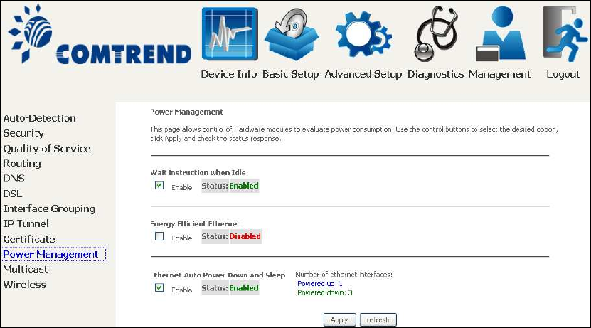
6.10 Power Management
This screen allows for control of hardware modules to evaluate power consumption.
Use the buttons to select the desired option, click Apply and check the response.
102
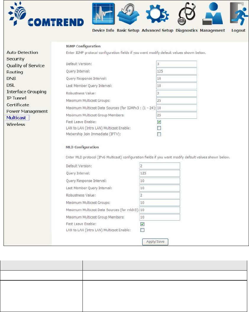
6.11 Multicast
Input new IGMP or MLD protocol configuration fields if you want modify default
values shown. Then click Apply/Save.
Field Description
Default Version Define IGMP using version with video server.
Query Interval The query interval is the amount of time in seconds
between IGMP General Query messages sent by the
router (if the router is the querier on this subnet). The
default query interval is 125 seconds.

103
Field Description
Query Response Interval The query response interval is the maximum amount
of time in seconds that the IGMP router waits to
receive a response to a General Query message. The
query response interval is the Maximum Response
Time field in the IGMP v2 Host Membership Query
message header. The default query response interval
is 10 seconds and must be less than the query
interval.
Last Member Query
Interval
The last member query interval is the amount of time
in seconds that the IGMP router waits to receive a
response to a Group-Specific Query message. The last
member query interval is also the amount of time in
seconds between successive Group-Specific Query
messages. The default last member query interval is
10 seconds.
Robustness Value The robustness variable is a way of indicating how
susceptible the subnet is to lost packets. IGMP can
recover from robustness variable minus 1 lost IGMP
packets. The robustness variable should be set to a
value of 2 or greater. The default robustness variable
value is 2.
Maximum Multicast
Groups
Setting the maximum number of Multicast groups.
Maximum Multicast Data
Sources (for IGMPv3)
Define the maximum multicast video stream number.
Maximum Multicast
Group Members
Setting the maximum number of groups that ports
can accept.
Fast Leave Enable When you enable IGMP fast-leave processing, the
switch immediately removes a port when it detects an
IGMP version 2 leave message on that port.
LAN to LAN (Intra LAN)
Multicast Enable
This will activate IGMP snooping for cases where
multicast data source and player are all located on the
LAN side.
Membership to join
Immediate (IPTV)
Enable IGMP immediate join feature for multicast
membership group.
104
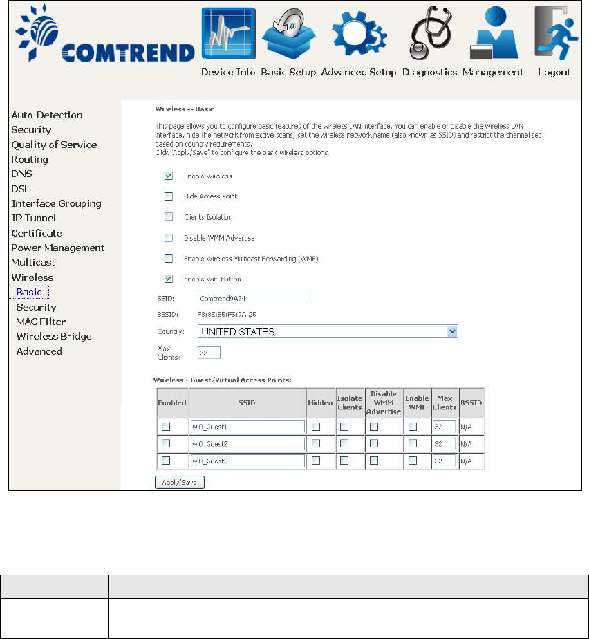
6.12 Wireless
6.12.1 Basic
The Basic option allows you to configure basic features of the wireless LAN interface.
Among other things, you can enable or disable the wireless LAN interface, hide the
network from active scans, set the wireless network name (also known as SSID)
and restrict the channel set based on country requirements.
Click Apply/Save to apply the selected wireless options.
Consult the table below for descriptions of these options.
Option Description
Enable
Wireless
A checkbox that enables or disables the wireless LAN interface.
When selected, a set of basic wireless options will appear.

105
Option Description
Hide Access
Point
Select Hide Access Point to protect the access point from detection
by wireless active scans. To check AP status in Windows XP, open
Network Connections from the start Menu and select View
Available Network Connections. If the access point is hidden, it
will not be listed there. To connect a client to a hidden access point,
the station must add the access point manually to its wireless
configuration.
Clients
Isolation
When enabled, it prevents client PCs from seeing one another in My
Network Places or Network Neighborhood. Also, prevents one
wireless client communicating with another wireless client.
Disable WMM
Advertise
Stops the router from ‘advertising’ its Wireless Multimedia (WMM)
functionality, which provides basic quality of service for
time-sensitive applications (e.g. VoIP, Video).
Enable
Wireless
Multicast
Forwarding
Select the checkbox to enable this function.
Enable WiFi
Button
Select the checkbox to enable the WiFi button.
SSID
[1-32
characters]
Sets the wireless network name. SSID stands for Service Set
Identifier. All stations must be configured with the correct SSID to
access the WLAN. If the SSID does not match, that user will not be
granted access.
BSSID The BSSID is a 48-bit identity used to identify a particular BSS
(Basic Service Set) within an area. In Infrastructure BSS
networks, the BSSID is the MAC (Media Access Control) address of
the AP (Access Point); and in Independent BSS or ad hoc networks,
the BSSID is generated randomly.
Country A drop-down menu that permits worldwide and specific national
settings. Local regulations limit channel range:
US= worldwide, Japan=1-14, Jordan= 10-13, Israel= 1-13
Max Clients The maximum number of clients that can access the router.
Wireless -
Guest /
Virtual
Access Points
This router supports multiple SSIDs called Guest SSIDs or Virtual
Access Points. To enable one or more Guest SSIDs select the
checkboxes in the Enabled column. To hide a Guest SSID select
its checkbox in the Hidden column.
Do the same for Isolate Clients and Disable WMM Advertise.
For a description of these two functions, see the previous entries for
“Clients Isolation” and “Disable WMM Advertise”. Similarly, for
Enable WMF, Max Clients and BSSID, consult the matching
entries in this table.
NOTE: Remote wireless hosts cannot scan Guest SSIDs.
106
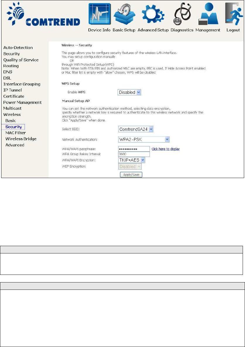
6.12.2 Security
The following screen appears when Wireless Security is selected. The options shown
here allow you to configure security features of the wireless LAN interface.
Click Apply/Save to implement new configuration settings.
WIRELESS SECURITY
Setup requires that the user configure these settings using the Web User Interface
(see the table below).
Select SSID
Select the wireless network name from the drop-down box. SSID stands for Service
Set Identifier. All stations must be confi
g
ured with the correct SSID to access the
WLAN. If the SSID does not match, that client will not be granted access.
Network Authentication
This option specifies whether a network key is used for authentication to the
wireless network. If network authentication is set to Open, then no authentication
is provided. Despite this, the identity of the client is still verified.
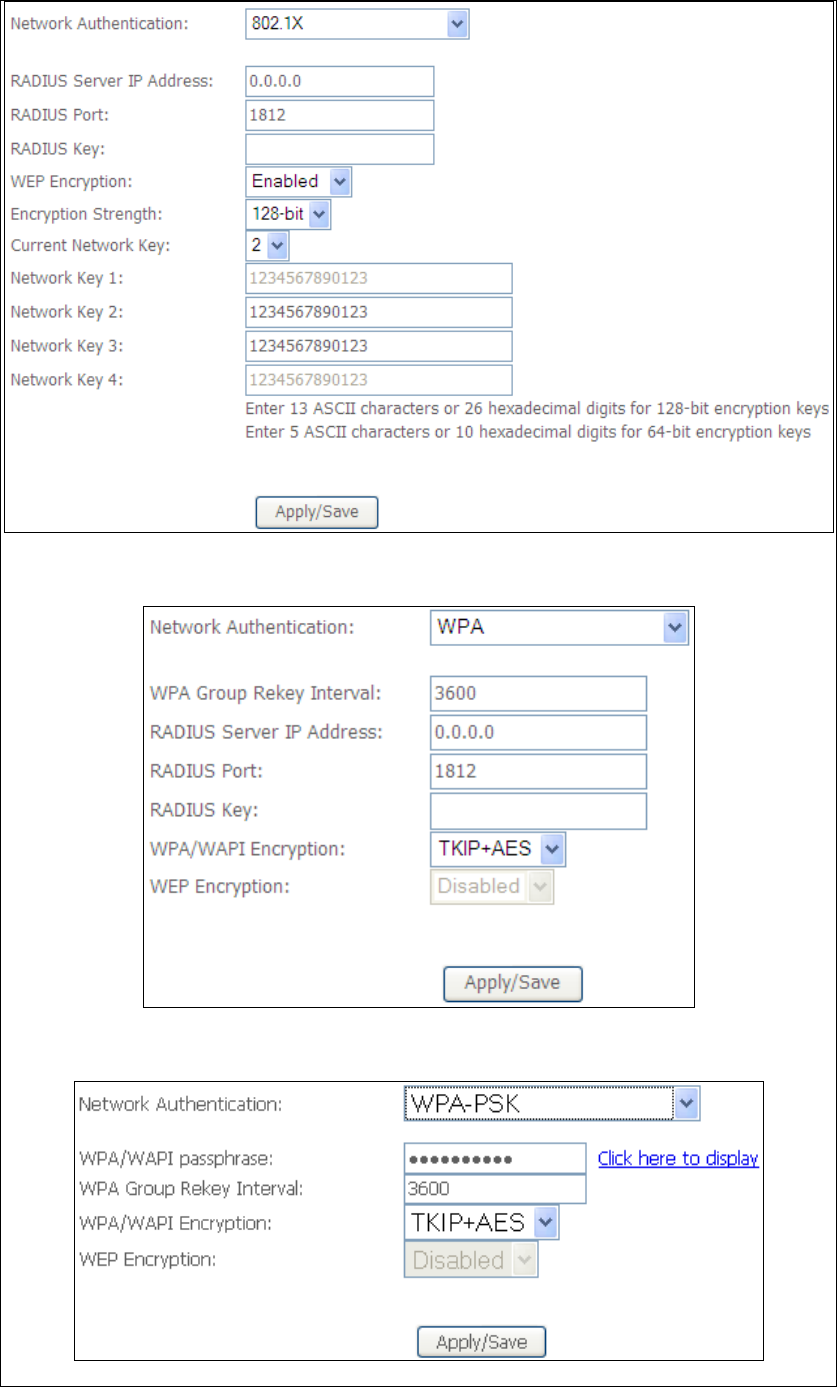
Each authentication type has its own settings. For example, selecting 802.1X
authentication will reveal the RADIUS Server IP address, Port and Key fields. WEP
Encryption will also be enabled as shown below.
107
The settings for WPA authentication are shown below.
The settings for WPA-PSK authentication are shown next.

108
WEP Encryption
This option specifies whether data sent over the network is encrypted. The same
network key is used for data encryption and network authentication. Four network
keys can be defined althou
g
h only one can be used at any one time. Use the Current
Network Key list box to select the appropriate network key.
Security options include authentication and encryption services based on the wired
equivalent privacy (WEP) algorithm. WEP is a set of security services used to
protect 802.11 networks from unauthorized access, such as eavesdroppin
g
; in this
case, the capture of wireless network traffic.
When data encryption is enabled, secret shared encryption keys are
g
enerated and
used by the source station and the destination station to alter frame bits, thus
avoiding disclosure to eavesdroppers.
Under shared key authentication, each wireless station is assumed to have received
a secret shared key over a secure channel that is independent from the 802.11
wireless network communications channel.
Encryption Strength
This drop-down list box will display when WEP Encryption is enabled. The key
strength is proportional to the number of binary bits comprising the key. This
means that keys with a
g
reater number of bits have a
g
reater de
g
ree of security and
are considerably more difficult to crack. Encryption strength can be set to either
64-bit or 128-bit. A 64-bit key is equivalent to 5 ASCII characters or 10
hexadecimal numbers. A 128-bit key contains 13 ASCII characters or 26
hexadecimal numbers. Each key contains a 24-bit header (an initiation vector)
which enables parallel decoding of multiple streams of encrypted data.
109
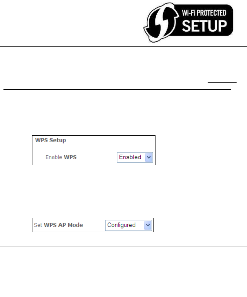
6.12.3 WPS
Wi-Fi Protected Setup (WPS) is an industry standard that simplifies wireless security
setup for certified network devices. Every WPS certified device has both a PIN
number and a push button, located on the device or accessed through device
software. The AR-5312u has a WPS button on the device.
Devices with the WPS logo (shown here)
support WPS. If the WPS logo is not present
on your device it still may support WPS, in
this case, check the device documentation
for the phrase “Wi-Fi Protected Setup”.
NOTE: WPS is only available in Open, WPA-PSK, WPA2-PSK and Mixed
WPA2/WPA-PSK network authentication modes. Other authentication
modes do not use WPS so they must be configured manually.
To configure security settings with WPS, follow the procedures below. You must
choose either the Push-Button or PIN configuration method for Steps 6 and 7.
I. Setup
Step 1: Enable WPS by selecting Enabled from the drop down list box shown.
Step 2: Set the WPS AP Mode. Configured is used when the AR-5312u will assign
security settings to clients. Unconfigured is used when an external
client assigns security settings to the AR-5312u.
NOTES: Your client may or may not have the ability to provide security settings to
the AR-5312u. If it does not, then you must set the WPS AP mode to
Configured. Consult the device documentation to check its capabilities.
In addition, using Windows 7, you can add an external registrar using the
Config AP button (Appendix F - WPS OPERATION has detailed
instructions).
110
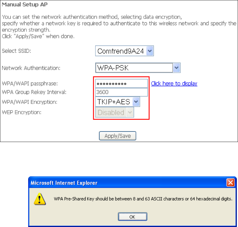
II. NETWORK AUTHENTICATION
Step 3: Select Open, WPA-PSK, WPA2-PSK, or Mixed WPA2/WPA-PSK network
authentication mode from the Manual Setup AP section of the Wireless
Security screen. The example below shows WPA2-PSK mode.
Step 4: For the Pre-Shared Key (PSK) modes, enter a WPA Pre-Shared Key. You
will see the following dialog box if the Key is too short or too long.
Step 5: Click the Apply/Save button at the bottom of the screen.
IIIa. PUSH-BUTTON CONFIGURATION
The WPS push-button configuration provides a semi-automated configuration
method. The WPS button on the rear panel of the router can be used for this
purpose or the Web User Interface (WUI) can be used exclusively.
The WPS push-button configuration is described in the procedure below. It is
assumed that the Wireless function is Enabled and that the router is configured as
the Wireless Access Point (AP) of your WLAN. In addition, the wireless client must
also be configured correctly and turned on, with WPS function enabled.
111
NOTE: The wireless AP on the router searches for 2 minutes. If the router stops
searching before you complete Step 7, return to Step 6.
Step 6: Press WPS button
Press the WPS button on the front panel of the router. The WPS LED will
blink to show that the router has begun searching for the client.
Step 7: Go to your WPS wireless client and activate the push-button function.
A typical WPS client screenshot is shown below as an example.
Now go to Step 8 (part IV. Check Connection) to check the WPS connection.
IIIb. WPS – PIN CONFIGURATION
Using this method, security settings are configured with a personal identification
number (PIN). The PIN can be found on the device itself or within the software.
The PIN may be generated randomly in the latter case. To obtain a PIN number for
your client, check the device documentation for specific instructions.
The WPS PIN configuration is described in the procedure below. It is assumed that
the Wireless function is Enabled and that the router is configured as the Wireless
Access Point (AP) of your wireless LAN. In addition, the wireless client must also be
configured correctly and turned on, with WPS function enabled.
NOTE: Unlike the push-button method, the pin method has no set time limit.
This means that the router will continue searching until it finds a client.
Step 6: Select the PIN radio button in the WSC Setup section of the Wireless
Security screen, as shown in A or B below, and then click the appropriate
button based on the WSC AP mode selected in step 2.
A - For Configured mode, click the Add Enrollee button.
Enter STA PIN: a Personal Identification Number (PIN) has to be read from either
a sticker or the display on the new wireless device. This PIN must then be inputted
at representing the network, usually the Access Point of the network.
B - For Unconfigured mode, click the Config AP button.
112
Step 7: Activate the PIN function on the wireless client. For Configured mode,
the client must be configured as an Enrollee. For Unconfigured mode,
the client must be configured as the Registrar. This is different from the
External Registrar function provided in Windows Vista.
The figure below provides an example of a WPS client PIN function in-progress.
Now go to Step 8 (part IV. Check Connection) to check the WPS connection.
IV. CHECK CONNECTION
Step 8: If the WPS setup method was successful, you will be able access the
wireless AP from the client. The client software should show the status.
The example below shows that the connection established successfully.
You can also double-click the Wireless Network Connection icon from the
Network Connections window (or the system tray) to confirm the status of
the new connection.
113
6.12.4 MAC Filter
This option allows access to the router to be restricted based upon MAC addresses.
To add a MAC Address filter, click the Add button shown below. To delete a filter,
select it from the MAC Address table below and click the Remove button.
Option Description
Select
SSID
Select the wireless network name from the drop-down box. SSID stands
for Service Set Identifier. All stations must be configured with the correct
SSID to access the WLAN. If the SSID does not match, that user will not
be granted access.
MAC
Restrict
Mode
Disabled: MAC filtering is disabled.
Allow: Permits access for the specified MAC addresses.
Deny: Rejects access for the specified MAC addresses.
MAC
Address
Lists the MAC addresses subject to the MAC Restrict Mode. A maximum
of 60 MAC addresses can be added. Every network device has a unique
48-bit MAC address. This is usually shown as xx.xx.xx.xx.xx.xx, where
xx are hexadecimal numbers.
After clicking the Add button, the following screen appears.
114
Enter the MAC address in the box provided and click Apply/Save.
115
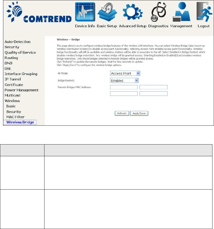
6.12.5 Wireless Bridge
This screen allows for the configuration of wireless bridge features of the WIFI
interface. See the table beneath for detailed explanations of the various options.
Click Apply/Save to implement new configuration settings.
Feature Description
AP Mode Selecting Wireless Bridge (aka Wireless Distribution System)
disables Access Point (AP) functionality, while selecting Access
Point enables AP functionality. In Access Point mode, wireless
bridge functionality will still be available and wireless stations
will be able to associate to the AP.
Bridge Restrict Selecting Disabled disables wireless bridge restriction, which
means that any wireless bridge will be granted access.
Selecting Enabled or Enabled (Scan) enables wireless bridge
restriction. Only those bridges selected in the Remote Bridges
list will be granted access. Click Refresh to update the station
list when Bridge Restrict is enabled.
116
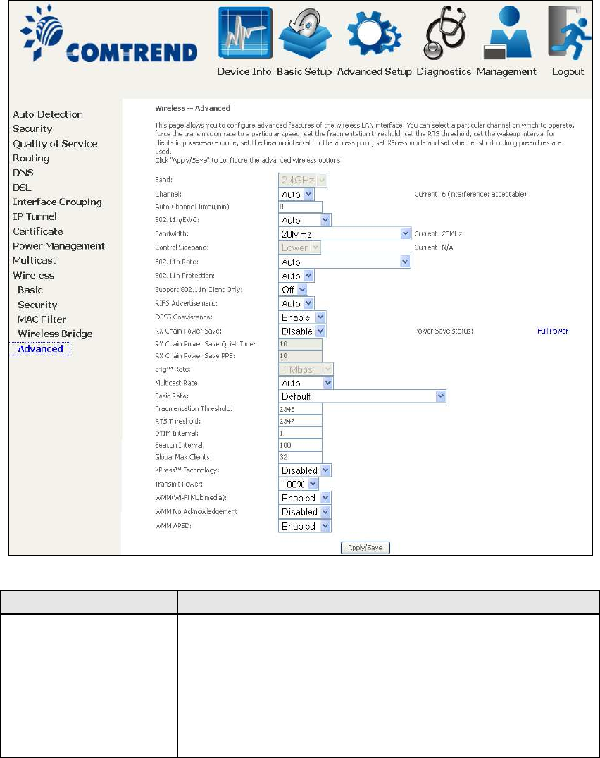
6.12.6 Advanced
The Advanced screen allows you to configure advanced features of the wireless LAN
interface. You can select a particular channel on which to operate, force the
transmission rate to a particular speed, set the fragmentation threshold, set the RTS
threshold, set the wakeup interval for clients in power-save mode, set the beacon
interval for the access point, set XPress mode and set whether short or long
preambles are used. Click Apply/Save to set new advanced wireless options.
Field Description
Band Set to 2.4 GHz for compatibility with IEEE 802.11x
standards. The new amendment allows IEEE 802.11n
units to fall back to slower speeds so that legacy IEEE
802.11x devices can coexist in the same network. IEEE
802.11g creates data-rate parity at 2.4 GHz with the IEEE
802.11a standard, which has a 54 Mbps rate at 5 GHz.
(IEEE 802.11a has other differences compared to IEEE
802.11b or g, such as offering more channels.)

117
Field Description
Channel Drop-down menu that allows selection of a specific
channel.
Auto Channel Timer
(min)
Auto channel scan timer in minutes (0 to disable)
802.11n/EWC An equipment interoperability standard setting based on
IEEE 802.11n Draft 2.0 and Enhanced Wireless
Consortium (EWC)
Bandwidth Select 20MHz or 40MHz bandwidth. 40MHz bandwidth
uses two adjacent 20MHz bands for increased data
throughput.
Control Sideband Select Upper or Lower sideband when in 40MHz mode.
802.11n Rate Set the physical transmission rate (PHY).
802.11n Protection Turn Off for maximized throughput.
Turn On for greater security.
Support 802.11n
Client Only
Turn Off to allow 802.11b/g clients access to the router.
Turn On to prohibit 802.11b/g client’s access to the router.
RIFS Advertisement One of several draft-n features designed to improve
efficiency. Provides a shorter delay between OFDM
transmissions than in802.11a or g.
OBSS Co-Existence Co-existence between 20 MHZ AND 40 MHZ overlapping
Basic Service Set (OBSS) in WLAN.
RX Chain Power Save Enabling this feature turns off one of the Receive chains,
going from 2x2 to 2x1 to save power.
RX Chain Power Save
Quiet Time
The number of seconds the traffic must be below the PPS
value below before the Rx Chain Power Save feature
activates itself.
RX Chain Power Save
PPS
The maximum number of packets per seconds that can be
processed by the WLAN interface for a duration of Quiet
Time, described above, before the Rx Chain Power Save
feature activates itself.
54g Rate Drop-down menu that specifies the followin
g
fixed rates:
Auto: Default. Uses the 11 Mbps data rate when possible
but drops to lower rates when necessary. 1 Mbps, 2Mbps,
5.5Mbps, or 11Mbps fixed rates. The appropriate setting
is dependent on signal strength.
Multicast Rate Setting for multicast packet transmit rate (1-54 Mbps)
Basic Rate Setting for basic transmission rate.
Fragmentation
Threshold
A threshold, specified in bytes, that determines whether
packets will be fragmented and at what size. On an
802.11 WLAN, packets that exceed the fragmentation
threshold are fragmented, i.e., split into, smaller units
suitable for the circuit size. Packets smaller than the
specified fragmentation threshold value are not
fragmented. Enter a value between 256 and 2346. If you
experience a high packet error rate, try to slightly increase
your Fragmentation Threshold. The value should remain
at its default setting of 2346. Setting the Fragmentation
Threshold too low may result in poor performance.

118
Field Description
RTS Threshold Request to Send, when set in bytes, specifies the packet
size beyond which the WLAN Card invokes its RTS/CTS
mechanism. Packets that exceed the specified RTS
threshold trigger the RTS/CTS mechanism. The NIC
transmits smaller packet without using RTS/CTS. The
default setting of 2347 (maximum length) disables RTS
Threshold.
DTIM Interval Delivery Traffic Indication Message (DTIM) is also known
as Beacon Rate. The entry range is a value between 1
and 65535. A DTIM is a countdown variable that informs
clients of the next window for listening to broadcast and
multicast messages. When the AP has buffered
broadcast or multicast messages for associated clients, it
sends the next DTIM with a DTIM Interval value. AP
Clients hear the beacons and awaken to receive the
broadcast and multicast messages. The default is 1.
Beacon Interval The amount of time between beacon transmissions in
milliseconds. The default is 100 ms and the acceptable
range is 1 – 65535. The beacon transmissions identify
the presence of an access point. By default, network
devices passively scan all RF channels listening for
beacons coming from access points. Before a station
enters power save mode, the station needs the beacon
interval to know when to wake up to receive the beacon
(and learn whether there are buffered frames at the
access point).
Global Max Clients The maximum number of clients that can connect to the
router.
Xpress
T
M
Technology Xpress Technology is compliant with draft specifications of
two planned wireless industry standards.
Transmi t Power Set the power output (by percentage) as desired.
WMM (Wi-Fi
Multimedia)
The technology maintains the priority of audio, video and
voice applications in a Wi-Fi network. It allows multimedia
service get higher priority.
WMM No
Acknowledgement
Refers to the acknowledge policy used at the MAC level.
Enabling no Acknowledgement can result in more efficient
throughput but higher error rates in a noisy Radio
Frequency (RF) environment.
WMM APSD This is Automatic Power Save Delivery. It saves power.

119
Chapter 7 Diagnostics
You can reach this page by clicking on the following icon located at the top of the
screen.
7.1 Diagnostics – Individual Tests
The first Diagnostics screen is a dashboard that shows overall connection status.
Click the Diagnostics Menu item on the left side of the screen to display the
individual connections.
120
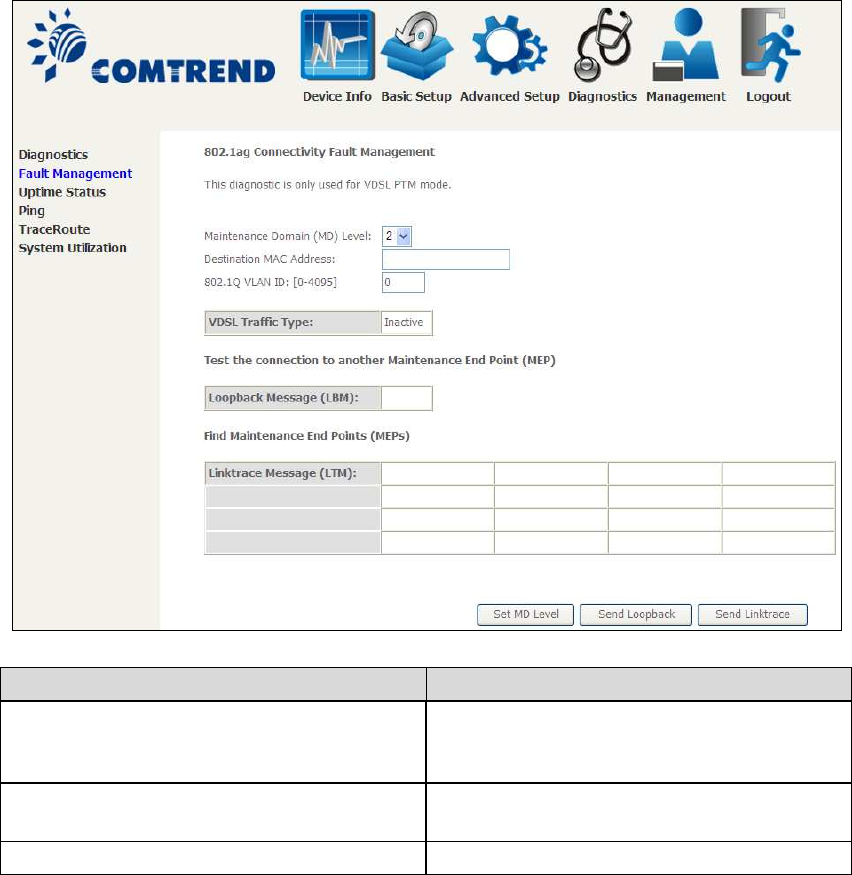
7.2 Fault Management
Item Description
Maintenance Domain (MD) Level Management space on the network, the
larger the domain, the higher the level
value
Destination MAC Address Destination MAC address for sending the
loopback message
802.1Q VLAN ID: [0-4095] 802.1Q VLAN used in VDSL PTM mode
Set MD Level
Save the Maintenance domain level.
Send Loopback
Send loopback message to destination MAC address.
Send Linktrace
Send traceroute message to destination MAC address.
121
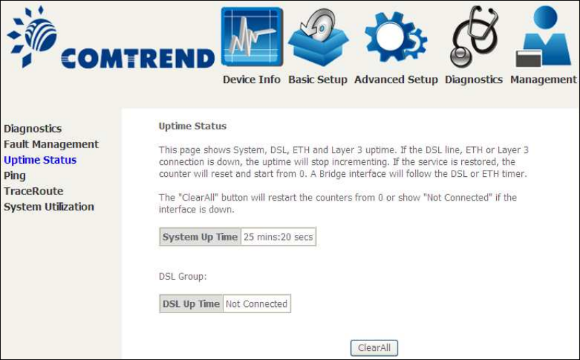
7.3 Uptime Status
This page shows System, DSL, ETH and Layer 3 uptime. If the DSL line, ETH or Layer
3 connection is down, the uptime will stop incrementing. If the service is restored,
the counter will reset and start from 0. A Bridge interface will follow the DSL or ETH
timer.
The "ClearAll" button will restart the counters from 0 or show "Not Connected" if the
interface is down.
122
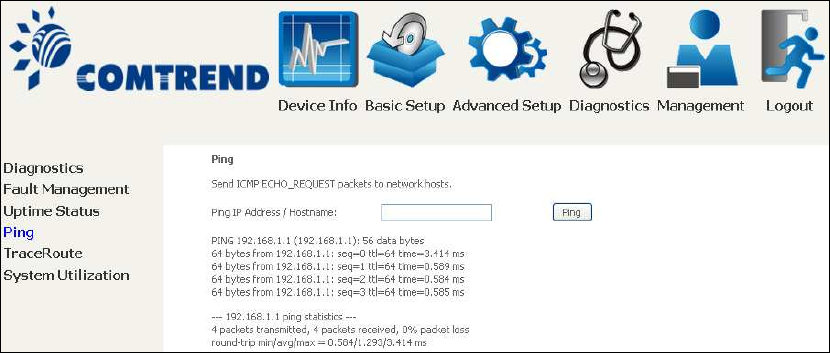
7.4 Ping
Input the IP address/hostname and click the Ping button to execute ping diagnostic
test to send the ICMP request to the specified host.
123
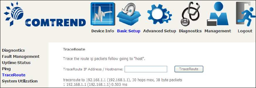
7.5 Trace Route
Input the IP address/hostname and click the TraceRoute button to execute the
trace route diagnostic test to send the ICMP packets to the specified host.
124
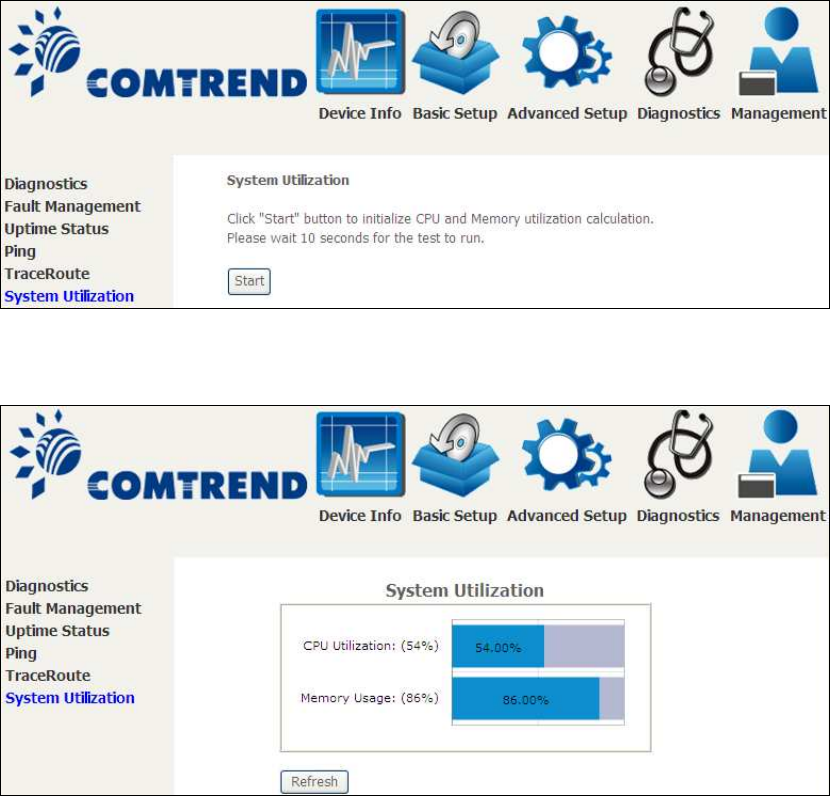
7.6 System Utilization
Click "Start" button to initialize CPU and Memory utilization calculation.
Please wait 10 seconds for the test to run.
125
Chapter 8 Management
You can reach this page by clicking on the following icon located at the top of the
screen.
The Management menu has the following maintenance functions and processes:
8.1 Settings
This includes Backup Settings, Update Settings, and Restore Default screens.
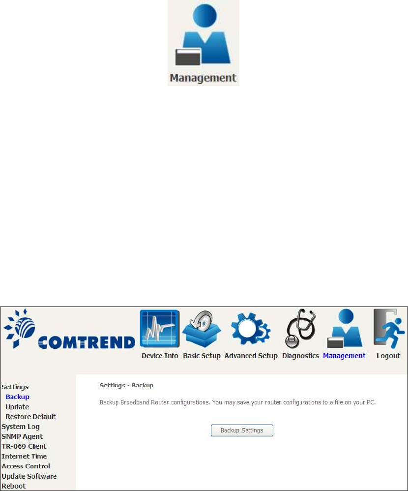
8.1.1 Backup Settings
To save the current configuration to a file on your PC, click Backup Settings. You
will be prompted for backup file location. This file can later be used to recover
settings on the Update Settings screen, as described below.
126
8.1.2 Update Settings
This option recovers configuration files previously saved using Backup Settings.
Enter the file name (including folder path) in the Settings File Name box, or press
Browse… to search for the file, then click Update Settings to recover settings.
8.1.3 Restore Default
Click Restore Default Settings to restore factory default settings.
After Restore Default Settings is clicked, the following screen appears.
Close the browser and wait for 2 minutes before reopening it. It may also be
necessary, to reconfigure your PC IP configuration to match any new settings.
NOTE: This entry has the same effect as the Reset button. The AR-5312u board
hardware and the boot loader support the reset to default. If the Reset
button is continuously pressed for more than 10 seconds, the boot loader
will erase the configuration data saved in flash memory.
127
8.2 System Log
This function allows a system log to be kept and viewed upon request.
Follow the steps below to configure, enable, and view the system log.
STEP 1: Click Configure System Log, as shown below (circled in Red).
STEP 2: Select desired options and click Apply/Save.
Consult the table below for detailed descriptions of each system log option.
Option Description
Log Indicates whether the system is currently recording events. The user
can enable or disable event logging. By default, it is disabled. To
enable it, select the Enable radio button and then click Apply/Save.

128
Option Description
Log
Level
Allows you to configure the event level and filter out unwanted events
below this level. The events ranging from the highest critical level
“Emergency” down to this configured level will be recorded to the log
buffer on the AR-5312u SDRAM. When the log buffer is full, the newer
event will wrap up to the top of the log buffer and overwrite the old event.
By default, the log level is “Debugging”, which is the lowest critical level.
The log levels are defined as follows:
• Emergency = system is unusable
• Alert = action must be taken immediately
• Critical = critical conditions
• Error = Error conditions
• Warning = normal but significant condition
• Notice= normal but insignificant condition
• Informational= provides information for reference
• Debugging = debug-level messages
Emergency is the most serious event level, whereas Debugging is the
least important. For instance, if the log level is set to Debugging, all the
events from the lowest Debugging level to the most critical level
Emergency level will be recorded. If the log level is set to Error, only
Error and the level above will be logged.
Display
Level
Allows the user to select the logged events and displays on the View
System Log window for events of this level and above to the highest
Emergency level.
Mode Allows you to specify whether events should be stored in the local
memory, or be sent to a remote system log server, or both
simultaneously. If remote mode is selected, view system log will not be
able to display events saved in the remote system log server.
When either Remote mode or Both mode is configured, the WEB UI will
prompt the user to enter the Server IP address and Server UDP port.
STEP 3: Click View System Log. The results are displayed as follows.
129
8.3 SNMP Agent
Simple Network Management Protocol (SNMP) allows a management application to
retrieve statistics and status from the SNMP agent in this device. Select the
Enable radio button, configure options, and click Save/Apply to activate SNMP.
130
8.4 TR-069 Client
WAN Management Protocol (TR-069) allows an Auto-Configuration Server (ACS) to
perform auto-configuration, provision, collection, and diagnostics to this device.
Select desired values and click Apply/Save to configure TR-069 client options.
The table below is provided for ease of reference.
Option Description
Enable TR-069 Tick the checkbox to enable.
OUI-serial The serial number used to identify the CPE when making a
connection to the ACS using the CPE WAN Management
Protocol. Select MAC to use the router’s MAC address as
serial number to authenticate with ACS or select serial
number to use router’s serial number.
Inform Disable/Enable TR-069 client on the CPE.
Inform Interval The duration in seconds of the interval for which the CPE
MUST attempt to connect with the ACS and call the Inform
method.

131
Option Description
ACS URL URL for the CPE to connect to the ACS using the CPE WAN
Management Protocol. This parameter MUST be in the form
of a valid HTTP or HTTPS URL. An HTTPS URL indicates that
the ACS supports SSL. The “host” portion of this URL is
used by the CPE for validating the certificate from the ACS
when using certificate-based authentication.
ACS User Name Username used to authenticate the CPE when making a
connection to the ACS using the CPE WAN Management
Protocol. This username is used only for HTTP-based
authentication of the CPE.
ACS Password Password used to authenticate the CPE when making a
connection to the ACS using the CPE WAN Management
Protocol. This password is used only for HTTP-based
authentication of the CPE.
WAN Interface used
by TR-069 client
Choose Any_WAN, LAN, Loopback or a configured
connection.
Connection Request
Authentication Tick the checkbox to enable.
User Name Username used to authenticate an ACS making a
Connection Request to the CPE.
Password Password used to authenticate an ACS making a
Connection Request to the CPE.
URL IP address and port the ACS uses to connect to router.
The Send Inform button forces the CPE to establish an immediate connection to
the ACS.
132
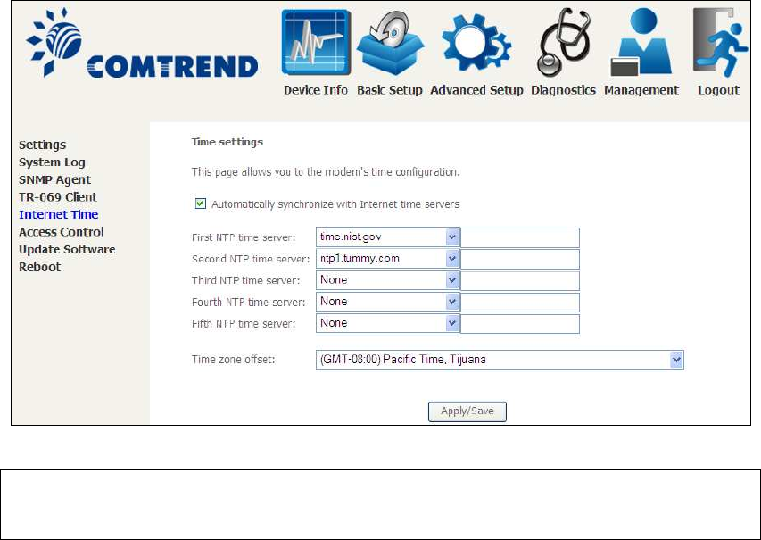
8.5 Internet Time
This option automatically synchronizes the router time with Internet timeservers.
To enable time synchronization, tick the corresponding checkbox , choose your
preferred time server(s), select the correct time zone offset, and click Save/Apply.
NOTE: Internet Time must be activated to use Parental Control.
In addition, this menu item is not displayed when in Bridge mode since
the router would not be able to connect to the NTP timeserver.
133
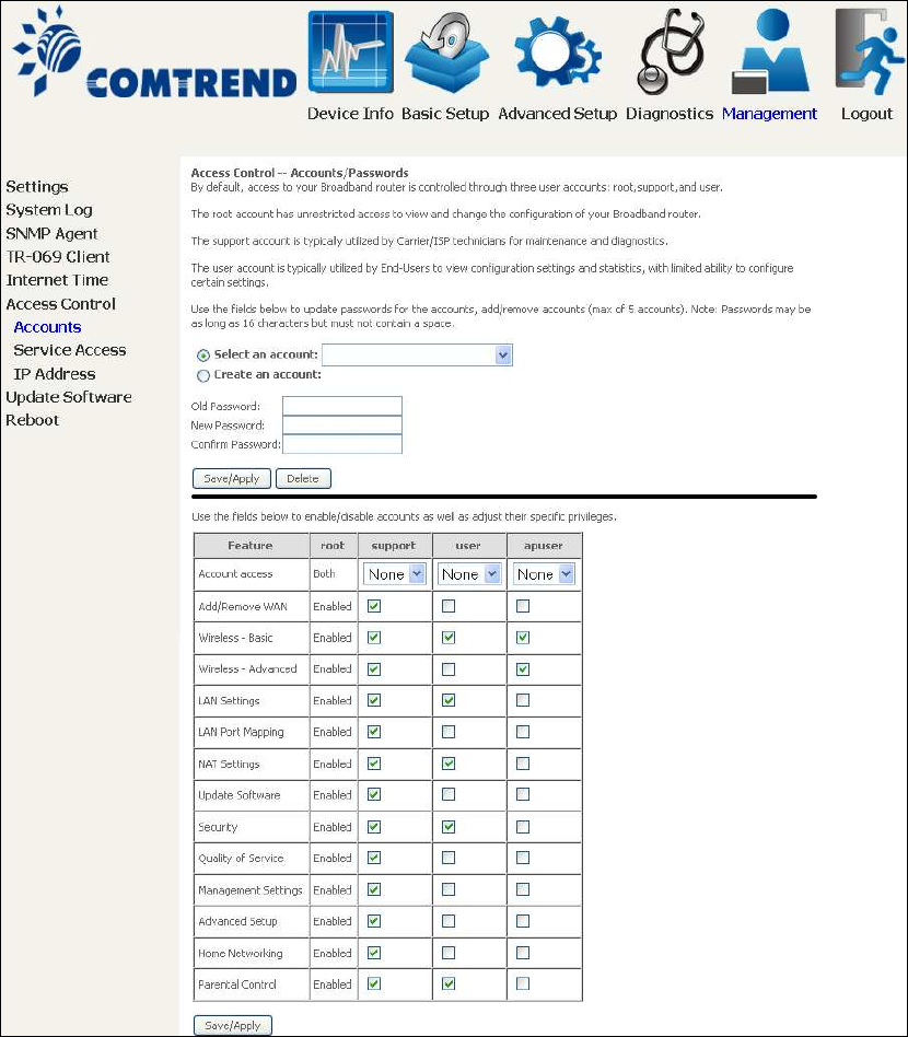
8.6 Access Control
8.6.1 Passwords
This screen is used to configure the user account access passwords for the device.
Access to the AR-5312u is controlled through the following user accounts:
•The root account has unrestricted access to view and change the
configuration of your Broadband router.
•The support account is typically utilized by Carrier/ISP technicians for
maintenance and diagnostics.
•The user account is typically utilized by End-Users to view configuration
settings and statistics, with limited ability to configure certain settings.
•The apuser account is typically utilized by End-Users to view configuration
settings and statistics, with limited ability to configure wireless settings.
Use the fields to update passwords for the accounts, add/remove accounts (max of
5 accounts) as well as adjust their specific privileges.
134
Note: Passwords may be as long as 16 characters but must not contain a space.
Click Save/Apply to continue.
135
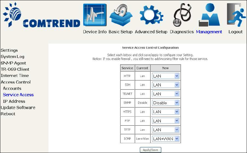
8.6.2 Service Access
The Services option limits or opens the access services over the LAN or WAN.
These access services available are: FTP, HTTP, ICMP, SNMP, TELNET and TFTP.
Enable a service by selecting its dropdown listbox. Click APPLY/SAVE to activate.
136
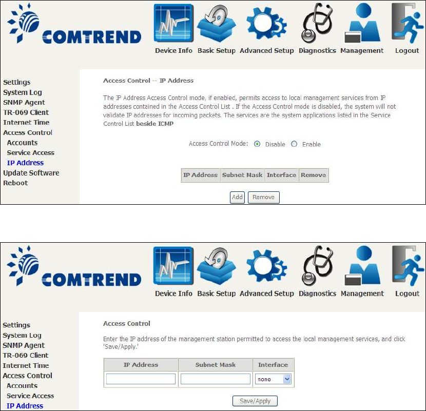
8.6.3 IP Address
The IP Address Access Control mode, if enabled, permits access to local
management services from IP addresses contained in the Access Control List. If the
Access Control mode is disabled, the system will not validate IP addresses for
incoming packets. The services are the system applications listed in the Service
Control List beside ICMP.
Click the Add button to display the following.
Configure the address and subnet of the management station permitted to access
the local management services, and click Save/Apply.
IP Address – IP address of the management station.
Subnet Mask – Subnet address for the management station.
Interface – Access permission for the specified address, allowing the address to
access the local management service from none/lan/wan/lan&wan interfaces.
137
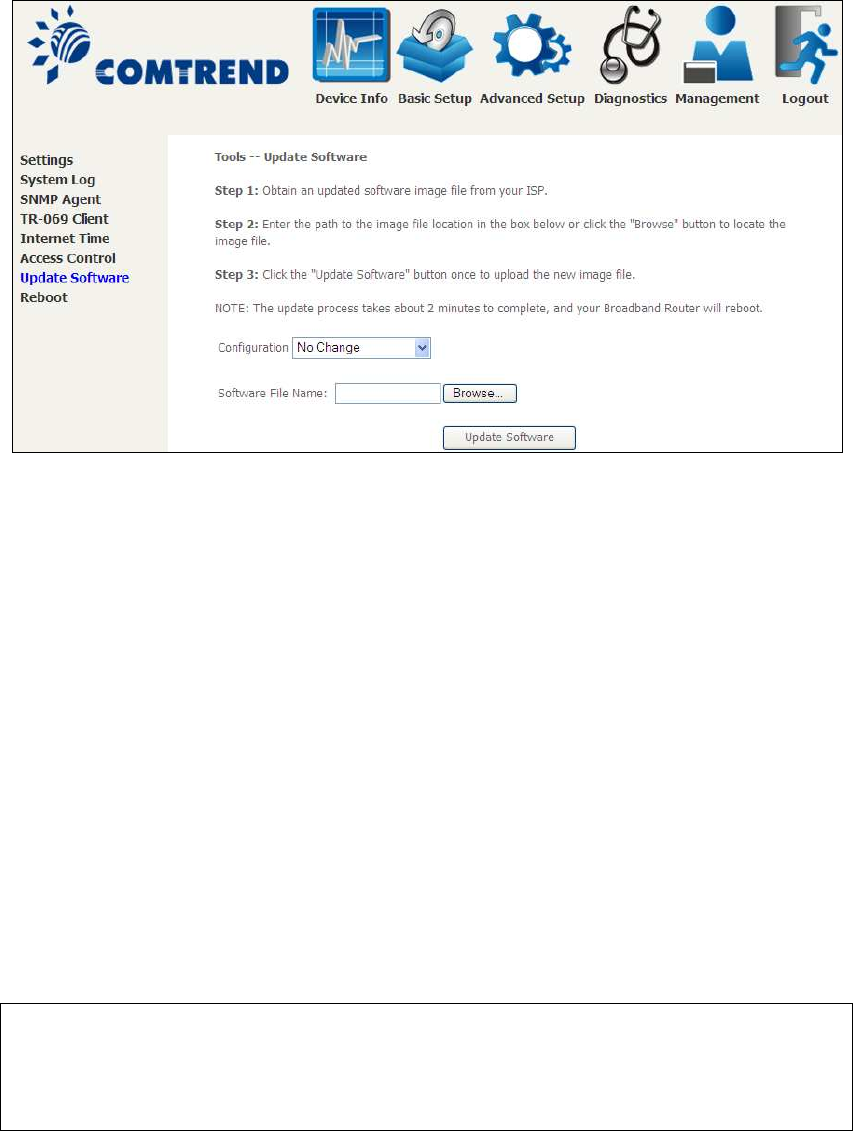
8.7 Update Software
This option allows for firmware upgrades from a locally stored file.
STEP 1: Obtain an updated software image file from your ISP.
STEP 2: Select the configuration from the drop-down menu.
Configuration options:
No change – upgrade software directly.
Erase current config – If the router has save_default configuration, this option will
erase the current configuration and restore to save_default configuration after
software upgrade.
Erase All – Router will be restored to factory default configuration after software
upgrade.
STEP 3: Enter the path and filename of the firmware image file in the Software
File Name field or click the Browse button to locate the image file.
STEP 4: Click the Update Software button once to upload and install the file.
NOTE: The update process will take about 2 minutes to complete. The device
will reboot and the browser window will refresh to the default screen upon
successful installation. It is recommended that you compare the
Software Version on the Device Information screen with the firmware
version installed, to confirm the installation was successful.
138
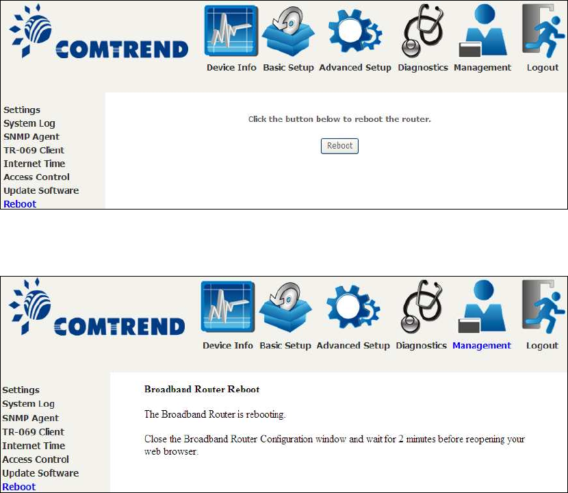
8.8 Reboot
To save the current configuration and reboot the router, click Save/Reboot.
NOTE: You may need to close the browser window and wait for 2 minutes before
reopening it. It may also be necessary, to reset your PC IP configuration.
139
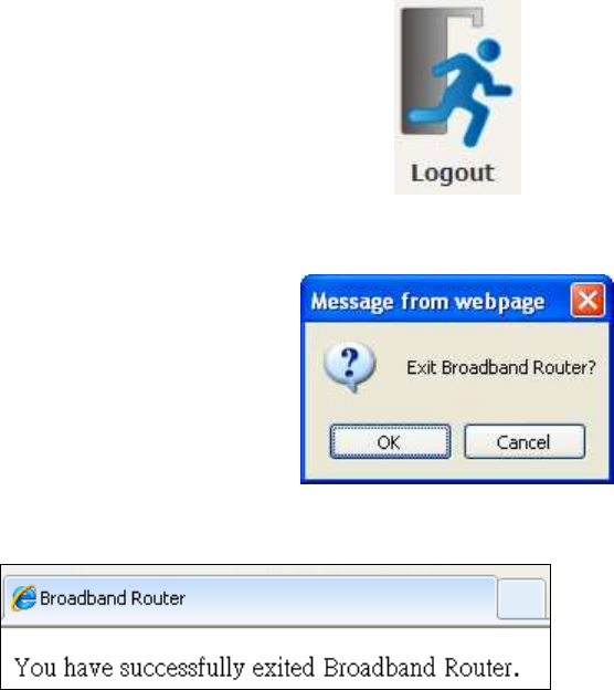
Chapter 9 Logout
To log out from the device simply click the following icon located at the top of your
screen.
When the following window pops up, click the OK button to exit the router.
Upon successful exit, the following message will be displayed.

140
Appendix A - Firewall
STATEFUL PACKET INSPECTION
Refers to an architecture, where the firewall keeps track of packets on each
connection traversing all its interfaces and makes sure they are valid. This is in
contrast to static packet filtering which only examines a packet based on the
information in the packet header.
DENIAL OF SERVICE ATTACK
Is an incident in which a user or organization is deprived of the services of a
resource they would normally expect to have. Various DoS attacks the device can
withstand are ARP Attack, Ping Attack, Ping of Death, Land, SYN Attack, Smurf
Attack, and Tear Drop.
TCP/IP/PORT/INTERFACE FILTER
These rules help in the filtering of traffic at the Network layer (i.e. Layer 3).
When a Routing interface is created, Enable Firewall must be checked.
Navigate to Advanced Setup Security IP Filtering.
OUTGOING IP FILTER
Helps in setting rules to DROP packets from the LAN interface. By default, if the
Firewall is Enabled, all IP traffic from the LAN is allowed. By setting up one or more
filters, specific packet types coming from the LAN can be dropped.
Example 1: Filter Name : Out_Filter1
Protocol : TCP
Source IP address : 192.168.1.45
Source Subnet Mask : 255.255.255.0
Source Port : 80
Dest. IP Address : NA
Dest. Subnet Mask : NA
Dest. Port : NA
This filter will Drop all TCP packets coming from the LAN with IP
Address/Subnet Mask of 192.168.1.45/24 having a source port of 80
irrespective of the destination. All other packets will be Accepted.
Example 2: Filter Name : Out_Filter2
Protocol : UDP
Source IP Address : 192.168.1.45
Source Subnet Mask : 255.255.255.0
Source Port : 5060:6060
Dest. IP Address : 172.16.13.4
Dest. Subnet Mask : 255.255.255.0
Dest. Port : 6060:7070
This filter will drop all UDP packets coming from the LAN with IP Address /
Subnet Mask of 192.168.1.45/24 and a source port range of 5060 to 6060,
destined to 172.16.13.4/24 and a destination port range of 6060 to 7070.
INCOMING IP FILTER
Helps in setting rules to Allow or Deny packets from the WAN interface. By default,
all incoming IP traffic from the WAN is Blocked, if the Firewall is Enabled. By setting
up one or more filters, specific packet types coming from the WAN can be Accepted.

141
Example 1: Filter Name : In_Filter1
Protocol : TCP
Policy : Allow
Source IP Address : 210.168.219.45
Source Subnet Mask : 255.255.0.0
Source Port : 80
Dest. IP Address : NA
Dest. Subnet Mask : NA
Dest. Port : NA
Selected WAN interface : br0
This filter will ACCEPT all TCP packets coming from WAN interface “br0” with IP
Address/Subnet Mask 210.168.219.45/16 with a source port of 80, irrespective
of the destination. All other incoming packets on this interface are DROPPED.
Example 2: Filter Name : In_Filter2
Protocol : UDP
Policy : Allow
Source IP Address : 210.168.219.45
Source Subnet Mask : 255.255.0.0
Source Port : 5060:6060
Dest. IP Address : 192.168.1.45
Dest. Sub. Mask : 255.255.255.0
Dest. Port : 6060:7070
Selected WAN interface : br0
This rule will ACCEPT all UDP packets coming from WAN interface “br0” with IP
Address/Subnet Mask 210.168.219.45/16 and a source port in the range of
5060 to 6060, destined to 192.168.1.45/24 and a destination port in the range
of 6060 to 7070. All other incoming packets on this interface are DROPPED.
MAC LAYER FILTER
These rules help in the filtering of Layer 2 traffic. MAC Filtering is only effective in
Bridge mode. After a Bridge mode connection is created, navigate to Advanced
Setup Security MAC Filtering in the WUI.
Example 1: Global Policy : Forwarded
Protocol Type : PPPoE
Dest. MAC Address : 00:12:34:56:78:90
Source MAC Address : NA
Src. Interface : eth1
Dest. Interface : eth2
Addition of this rule drops all PPPoE frames going from eth1 to eth2 with a
Destination MAC Address of 00:12:34:56:78:90 irrespective of its Source MAC
Address. All other frames on this interface are forwarded.
Example 2: Global Policy : Blocked
Protocol Type : PPPoE
Dest. MAC Address : 00:12:34:56:78:90
Source MAC Address : 00:34:12:78:90:56
Src. Interface : eth1
Dest. Interface : eth2
Addition of this rule forwards all PPPoE frames going from eth1 to eth2 with a
Destination MAC Address of 00:12:34:56:78 and Source MAC Address of
00:34:12:78:90:56. All other frames on this interface are dropped.

142
DAYTIME PARENTAL CONTROL
This feature restricts access of a selected LAN device to an outside Network through
the AR-5312u , as per chosen days of the week and the chosen times.
Example: User Name : FilterJohn
Browser's MAC Address : 00:25:46:78:63:21
Days of the Week : Mon, Wed, Fri
Start Blocking Time : 14:00
End Blocking Time : 18:00
With this rule, a LAN device with MAC Address of 00:25:46:78:63:21 will have
no access to the WAN on Mondays, Wednesdays, and Fridays, from 2pm to 6pm.
On all other days and times, this device will have access to the outside
Network.

143
Appendix B - Pin Assignments
ETHERNET Ports (RJ45)
ETHERNET LAN Ports (10/100Base-T)
Table 1
Pin Definition Pin Definition
1 Transmit data+ 5 NC
2 Transmit data- 6 Receive data-
3 Receive data+ 7 NC
4 NC 8 NC
Signals for ETHERNET WAN port (10/1001000Base-T)
Table 2
Pin Signal name Signal definition
1 TRD+(0) Transmit/Receive data 0 (positive lead)
2 TRD-(0) Transmit/Receive data 0 (negative lead)
3 TRD+(1) Transmit/Receive data 1 (positive lead)
4 TRD+(2) Transmit/Receive data 2 (positive lead)
5 TRD-(2) Transmit/Receive data 2 (negative lead)
6 TRD-(1) Transmit/Receive data 1 (negative lead)
7 TRD+(3) Transmit/Receive data 3 (positive lead)
8 TRD-(3) Transmit/Receive data 3 (negative lead)
DSL Port
Table 3
Pin Signal definition
1
LINE2 TIP
2
LINE1 TIP
3
LINE1 RING
4
LINE2 RING
144
Appendix C – Specifications
Hardware Interface
RJ-11 X 1 for ADSL
RJ-45 X 4 for LAN (10/100 Base-T auto-sense)
WPS/Wi-Fi Button X 1
On/Off Button X 1
Reset Button X 1
USB Host X 1
Wi-Fi Antenna X 2
WAN Interface
Downstream up to 12M for ADSL, 24 Mbps for ADSL2+; Upstream up to 1.3
Mbps,
ITU-T G.992.5, ITU-T G.992.3, ITU-T G.992.1, ANSI T1.413 Issue 2, Annex
A/L/M
LAN Interface
Standard IEEE 802.3, IEEE 802.3u
Support MDI/MDX
10/100 Base T Auto-sense
Wireless Interface
IEEE802.11b/g/n
64, 128-bit Wired Equivalent Privacy (WEP) Data Encryption
11 Channels (US, Canada)/ 13 Channels (Europe)/ 14 Channels (Japan)
WDS/WEP/WPA/WPA2 Yes
Management
Remote upgrade
TFTP/FTP upgrade
Telnet remote access support
Support Web based configuration
Support for backup & restore configuration to/from PC
Networking Protocols
•RFC 2684 VC-MUX, LLC/SNAP encapsulations for bridged or routed packet
•RFC 2364 PPP over AAL5
•IPoA, PPPoA, PPPoE, Multiple PPPoE sessions on single PVC, PPPoE pass-through
•PPPoE filtering of on-PPPoE packets between WAN and LAN
•Transparent bridging between all LAN and WAN interfaces
•802.1p/802.1q VLAN support
•Spanning Tree Algorithm
•IGMP Proxy V1/V2/V3, IGMP Snooping V1/V2/V3, Fast leave
•Static route, RIP v1/v2, ARP, RARP, SNTP
•DHCP Server/Client/Relay,
•DNS Proxy/Relay, Dynamic DNS,
•UPnP IGD v1.0
•IPv6 subset

145
Security Functions
•PAP, CHAP, Packet and MAC address filtering, SSH
•VPN termination
•Three level login including local admin, local user and remote technical support
access
QoS
•Packet level QoS classification rules,
•Priority queuing using ATM/PTM TX queues,
•IP TOS/Precedence,
•802.1p marking,
•DiffServ DSCP marking
•Src/dest MAC addresses classification
Firewall/Filtering
Stateful Inspection Firewall
Stateless Packet Filter
Denial of Service (DOS): ARP attacks, Ping attacks, Ping of Death, LAND,SYNC,
Smurf, Unreachable, Teardrop
TCP/IP/Port/interface filtering rules Support both incoming and outgoing
filtering
NAT/NAPT
Support Port Triggering and Port forwarding
Symmetric port-overloading NAT, Full-Cone NAT
Dynamic NAPT (NAPT N-to-1)
Support DMZ host
Virtual Server (Port forwarding)
VPN Passthrough (PPTP, L2TP, IPSec)
Application Passthrough
PPTP, L2TP, IPSec, Yahoo messenger, ICQ, RealPlayer, NetMeeting, MSN, X-box, etc.
Power Supply ................................................Input: 100 - 240 Vac
Output: 12 Vdc / 0.5 A
Environment Condition
Operating temperature ...........................0 ~ 40 degrees Celsius
Humidity…………………….10 ~ 90% (non-condensing, standard operating)
Dimensions .................................. 173 mm (W) x 39 mm (H) x 135.8 mm (D)
Certifications................................... CE
Kit Weight
(1*AR-5312u, 1*RJ11 cable, 1*RJ45 cable, 1*power adapter, 1*CD-ROM)
NOTE: Specifications are subject to change without notice

146
Appendix D - SSH Client
Unlike Microsoft Windows, Linux OS has a ssh client included. For Windows users,
there is a public domain one called “putty” that can be downloaded from here:
http://www.chiark.greenend.org.uk/~sgtatham/putty/download.html
To access the ssh client you must first enable SSH access for the LAN or WAN from
the Management Access Control Services menu in the web user interface.
To access the router using the Linux ssh client
For LAN access, type: ssh -l root 192.168.1.1
For WAN access, type: ssh -l support WAN IP address
To access the router using the Windows “putty” ssh client
For LAN access, type: putty -ssh -l root 192.168.1.1
For WAN access, type: putty -ssh -l support WAN IP address
NOTE: The WAN IP address can be found on the Device Info WAN screen
147
Appendix E - Connection Setup
Creating a WAN connection is a two-stage process.
1 - Setup a Layer 2 Interface (ATM, PTM or Ethernet).
2 - Add a WAN connection to the Layer 2 Interface.
The following sections describe each stage in turn.
E1 ~ Layer 2 Interfaces
Every layer2 interface operates in Multi-Service Connection (VLAN MUX) mode,
which supports multiple connections over a single interface. Note that PPPoA and
IPoA connection types are not supported for Ethernet WAN interfaces. After adding
WAN connections to an interface, you must also create an Interface Group to
connect LAN/WAN interfaces.
E1.1 ATM Interfaces
Follow these procedures to configure an ATM interface.
NOTE: The AR-5312u supports up to 16 ATM interfaces.
STEP 1: Go to Basic Setup WAN Setup Select ATM Interface from the
drop-down menu.
This table is provided here for ease of reference.

148
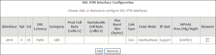
Heading Description
Interface WAN interface name.
VPI ATM VPI (0-255)
VCI ATM VCI (32-65535)
DSL Latency {Path0} portID = 0
{Path1} port ID = 1
{Path0&1} port ID = 4
Category ATM service category
Peak Cell Rate Maximum allowed traffic rate for the ATM PCR service
connection
Sustainable Cell
Rate
The average allowable, long-term cell transfer rate on the VBR
service connection
Max Burst Size The maximum allowable burst size of cells that can be
transmitted contiguously on the VBR service connection
Link Type Choose EoA (for PPPoE, IPoE, and Bridge), PPPoA, or IPoA.
Connection Mode Default Mode – Single service over one connection
Vlan Mux Mode – Multiple Vlan service over one connection
IP QoS Quality of Service (QoS) status
MPAAL QoS Scheduler algorithm and queue weight defined for the
connection
Remove Select items for removal
STEP 2: Click Add to proceed to the next screen.
NOTE: To add WAN connections to one interface type, you must delete existing
connections from the other interface type using the remove button.
149
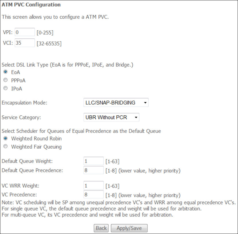
There are many settings here including: VPI/VCI, DSL Link Type, Encapsulation
Mode, Service Category, Connection Mode and Quality of Service.
Here are the available encapsulations for each xDSL Link Type:
EoA- LLC/SNAP-BRIDGING, VC/MUX
PPPoA- VC/MUX, LLC/ENCAPSULATION
IPoA- LLC/SNAP-ROUTING, VC MUX
STEP 3: Click Apply/Save to confirm your choices.
On the next screen, check that the ATM interface is added to the list. For example,
an ATM interface on PVC 0/35 in Default Mode with an EoA Link type is shown below.
150
To add a WAN connection go to E2 ~ WAN Connections.
151
E1.2 PTM Interfaces
Follow these procedures to configure a PTM interface.
NOTE: The AR-5312u supports up to four PTM interfaces.
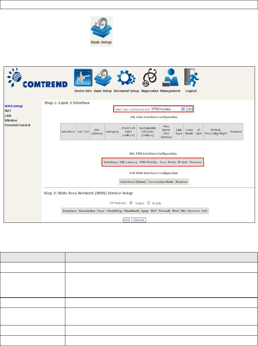
STEP 4: Go to Basic Setup WAN Setup Select PTM Interface from the
drop-down menu.
This table is provided here for ease of reference.
Heading Description
Interface WAN interface name.
DSL Latency {Path0} portID = 0
{Path1} port ID = 1
{Path0&1} port ID = 4
PTM Priority Normal or High Priority (Preemption).
Connection Mode Default Mode – Single service over one interface.
Vlan Mux Mode – Multiple Vlan services over one interface.
IP QoS Quality of Service (QoS) status.
Remove Select interfaces to remove.
STEP 5: Click Add to proceed to the next screen.
152
NOTE: To add WAN connections to one interface type, you must delete existing
connections from the other interface type using the remove button.
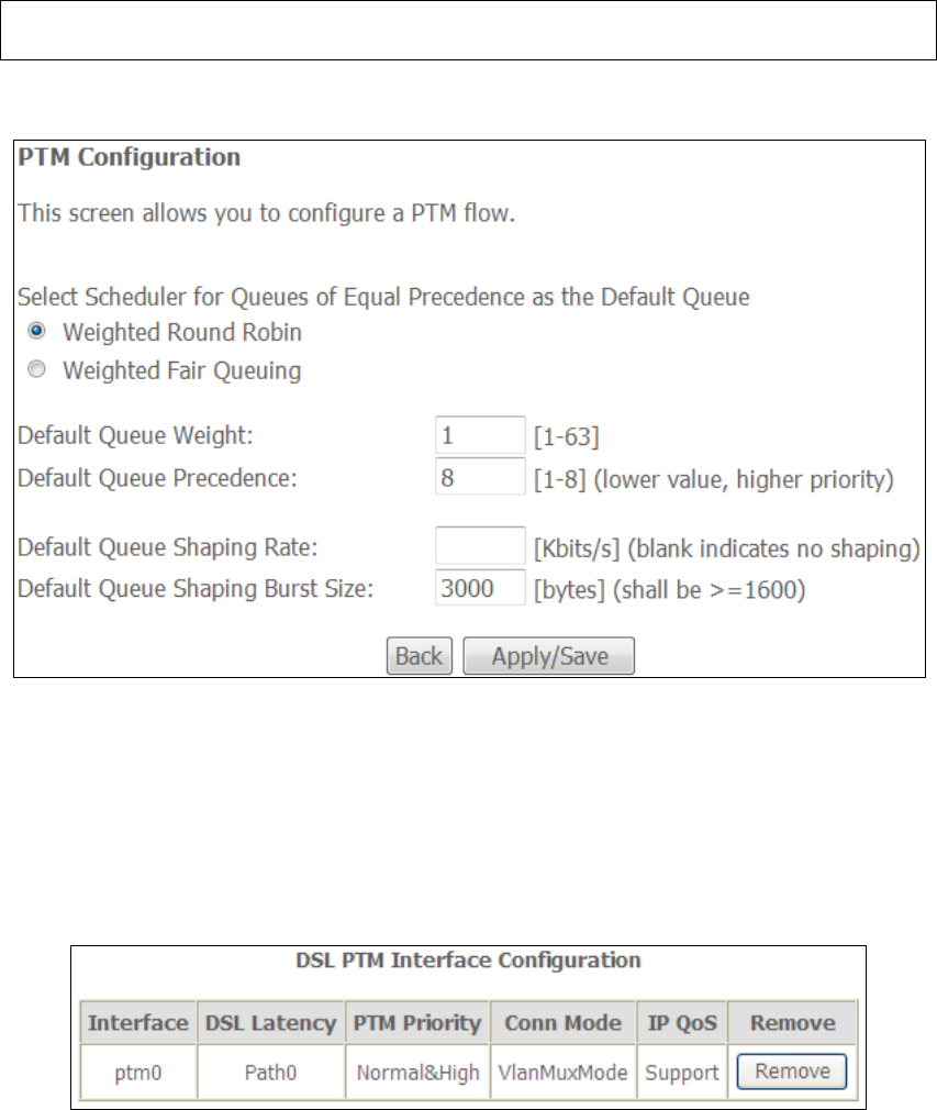
There are many settings that can be configured here including:
PTM Priority, Connection Mode and Quality of Service.
STEP 6: Click Apply/Save to confirm your choices.
On the next screen, check that the PTM interface is added to the list.
For example, an PTM interface in Default Mode is shown below.
To add a WAN connection go to section E2 WAN Connections.
153
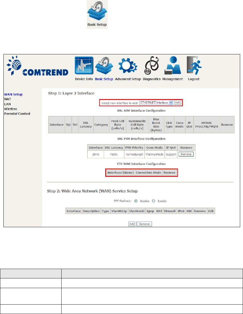
E1.3 ETHERNET Interfaces
Follow these procedures to configure a PTM interface.
STEP 1: Go to Basic Setup WAN Setup Select ETHERNET Interface
from the drop-down menu.
This table is provided here for ease of reference.
Heading Description
Interface/ (Name) WAN interface name.
Connection Mode Default Mode – Single service over one interface.
Vlan Mux Mode – Multiple Vlan services over one interface.
Remove Select interfaces to remove.
STEP 2: Click Add to proceed to the next screen.
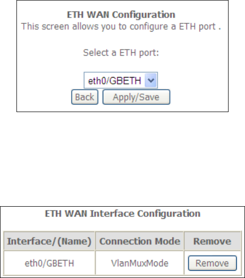
154
STEP 3: Select an Ethernet port and Click Apply/Save to confirm your choices.
On the next screen, check that the ETHERNET interface is added to the list.
155
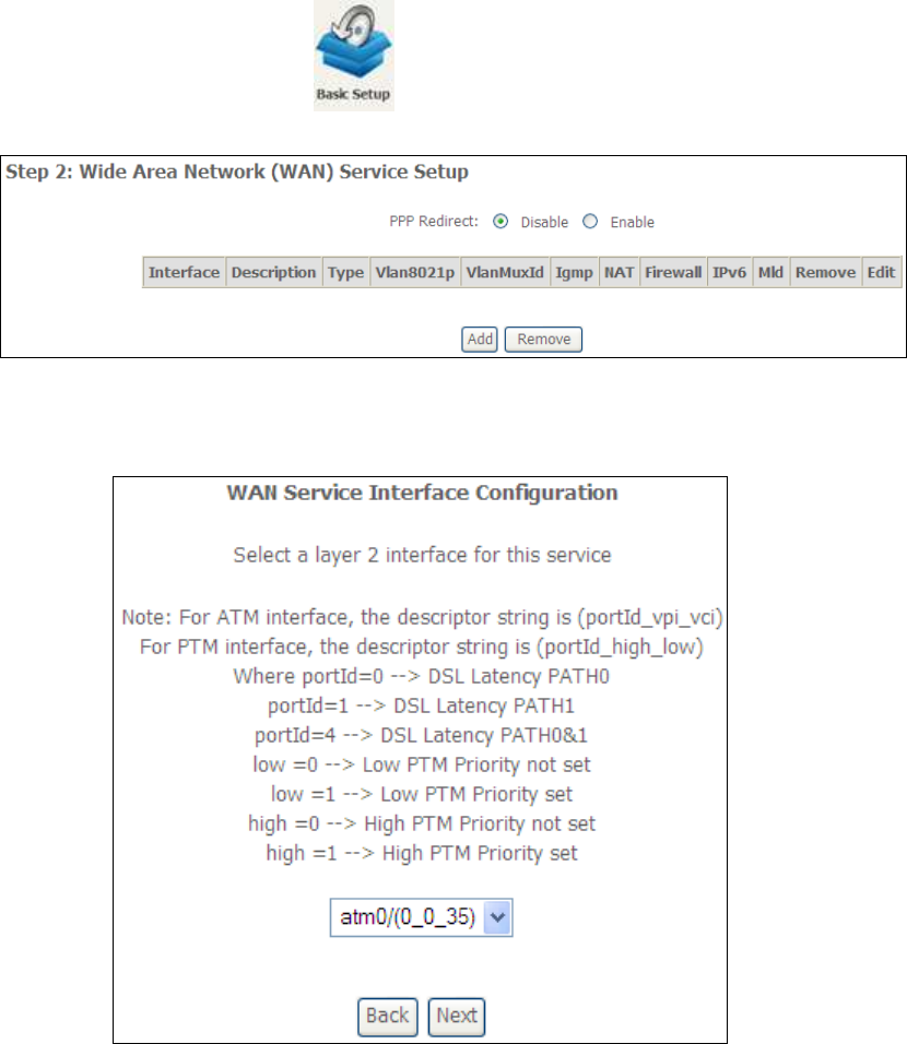
E2 ~ WAN Connections
The AR-5312u supports one WAN connection for each interface, up to a maximum of
16 connections.
To setup a WAN connection follow these instructions.
STEP 1: Go to Basic Setup WAN Setup.
STEP 2: Click Add to create a WAN connection. The following screen will display.
156
STEP 3: Choose a layer 2 interface from the drop-down box and click Next.
The WAN Service Configuration screen will display as shown below.
NOTE: The WAN services shown here are those supported by the layer 2
interface you selected in the previous step. If you wish to change your
selection click the Back button and select a different layer 2 interface.
STEP 4: For VLAN Mux Connections only, you must enter Priority & VLAN ID tags.
STEP 5: You will now follow the instructions specific to the WAN service type you
wish to establish. This list should help you locate the correct procedure:
(1) For PPP over ETHERNET (PPPoE), go to page 157.
(2) For IP over ETHERNET (IPoE), go to page 163.
(3) For Bridging, go to page 168.
(4) For PPP over ATM (PPPoA), go to page 170.
(5) For IP over ATM (IPoA), go to page 175.
The subsections that follow continue the WAN service setup procedure.
157
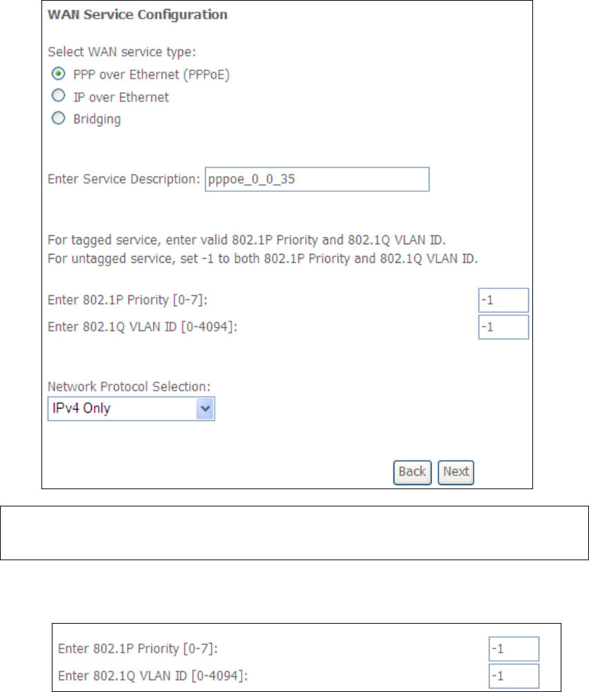
E2.1 PPP over ETHERNET (PPPoE)
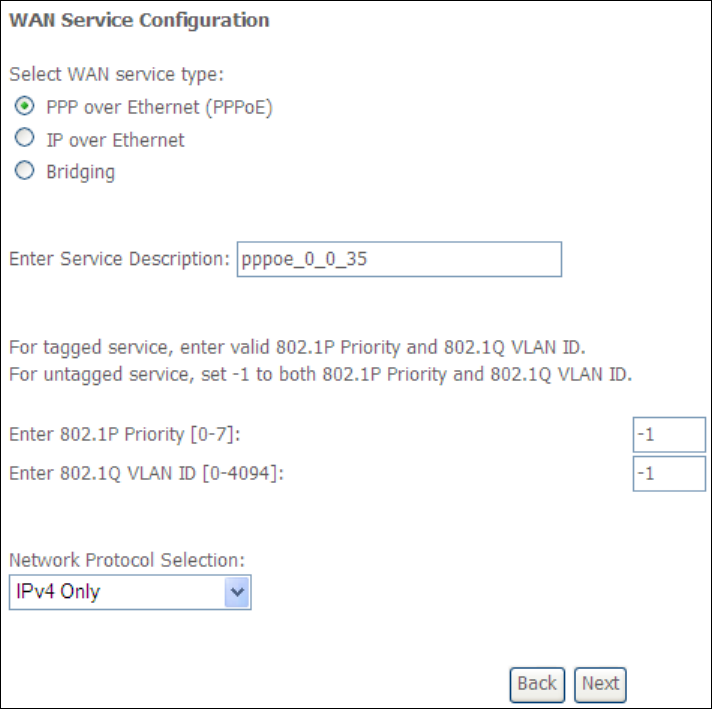
STEP 1: Select the PPP over Ethernet radio button and click Next. You can also
enable IPv6 by ticking the checkbox at the bottom of this screen.
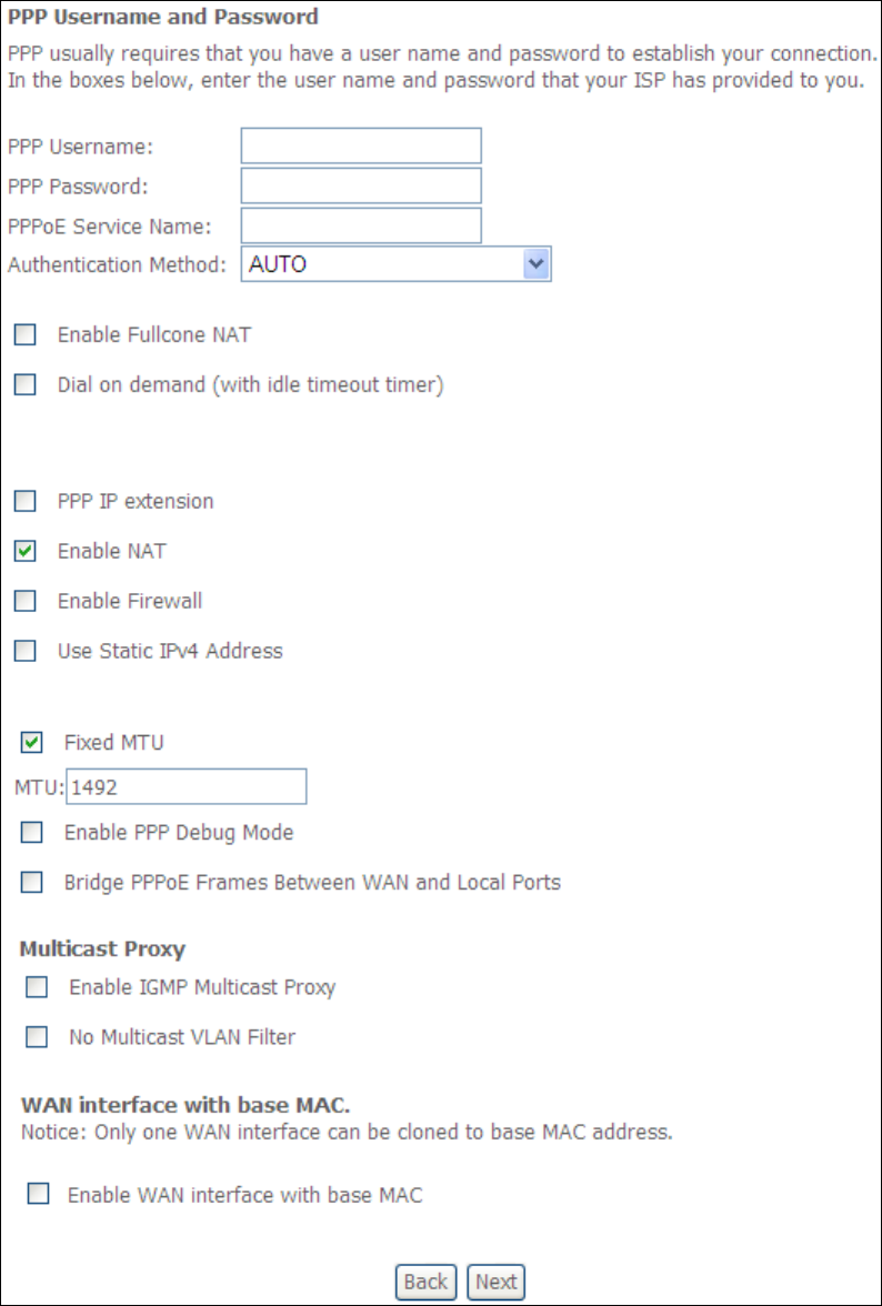
STEP 2: On the next screen, enter the PPP settings as provided by your ISP.
Click Next to continue or click Back to return to the previous step.
158
The settings shown above are described below.
PPP SETTINGS
The PPP Username, PPP password and the PPPoE Service Name entries are
dependent on the particular requirements of the ISP. The user name can be a
maximum of 256 characters and the password a maximum of 32 characters in
length. For Authentication Method, choose from AUTO, PAP, CHAP, and MSCHAP.

159
ENABLE FULLCONE NAT
This option becomes available when NAT is enabled. Known as one-to-one NAT, all
requests from the same internal IP address and port are mapped to the same
external IP address and port. An external host can send a packet to the internal host,
by sending a packet to the mapped external address.
DIAL ON DEMAND
The AR-5312u can be configured to disconnect if there is no activity for a period of
time by selecting the Dial on demand checkbox . You must also enter an
inactivity timeout period in the range of 1 to 4320 minutes.
PPP IP EXTENSION
The PPP IP Extension is a special feature deployed by some service providers.
Unless your service provider specifically requires this setup, do not select it.
PPP IP Extension does the following:
• Allows only one PC on the LAN.
• Disables NAT and Firewall.
• The device becomes the default gateway and DNS server to the PC
through DHCP using the LAN interface IP address.
• The device extends the IP subnet at the remote service provider to the
LAN PC. i.e. the PC becomes a host belonging to the same IP subnet.
• The device bridges the IP packets between WAN and LAN ports, unless
the packet is addressed to the device’s LAN IP address.
• The public IP address assigned by the remote side using the PPP/IPCP
protocol is actually not used on the WAN PPP interface. Instead, it is
forwarded to the PC LAN interface through DHCP. Only one PC on the
LAN can be connected to the remote, since the DHCP server within the
device has only a single IP address to assign to a LAN device.
ENABLE NAT
If the LAN is configured with a private IP address, the user should select this
checkbox . The NAT submenu will appear in the Advanced Setup menu after reboot.
On the other hand, if a private IP address is not used on the LAN side (i.e. the LAN
side is using a public IP), this checkbox should not be selected to free up system
resources for better performance.
ENABLE FIREWALL
If this checkbox is selected, the Security submenu will be displayed on the
Advanced Setup menu after reboot. If firewall is not necessary, this checkbox
should not be selected to free up system resources for better performance.
USE STATIC IPv4 ADDRESS
Unless your service provider specially requires it, do not select this checkbox . If
selected, enter the static IP address in the IPv4 Address field.
Don’t forget to adjust the IP configuration to Static IP Mode as described in section
3.2.
160
FIXED MTU
Maximum Transmission Unit. The size (in bytes) of largest protocol data unit which
the layer can pass onwards. This value is 1500 for PPPoA.
ENABLE PPP DEBUG MODE
When this option is selected, the system will put more PPP connection information
into the system log. This is for debugging errors and not for normal usage.
BRIDGE PPPOE FRAMES BETWEEN WAN AND LOCAL PORTS
(This option is hidden when PPP IP Extension is enabled)
When Enabled, this creates local PPPoE connections to the WAN side. Enable this
option only if all LAN-side devices are running PPPoE clients, otherwise disable it.
The AR-5312u supports pass-through PPPoE sessions from the LAN side while
simultaneously running a PPPoE client from non-PPPoE LAN devices.
ENABLE IGMP MULTICAST PROXY
Tick the checkbox to enable Internet Group Membership Protocol (IGMP)
multicast. This protocol is used by IPv4 hosts to report their multicast group
memberships to any neighboring multicast routers.
NO MULTICAST VLAN FILTER
Tick the checkbox to Enable/Disable multicast VLAN filter.
Enable WAN interface with base MAC
Enable this option to use the router’s base MAC address as the MAC address for this
WAN interface.
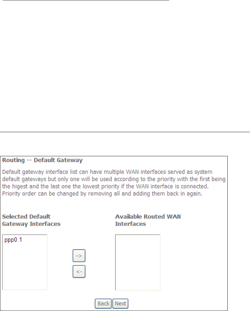
STEP 3: Choose an interface to be the default gateway.
Click Next to continue or click Back to return to the previous step.
161
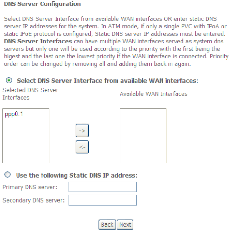
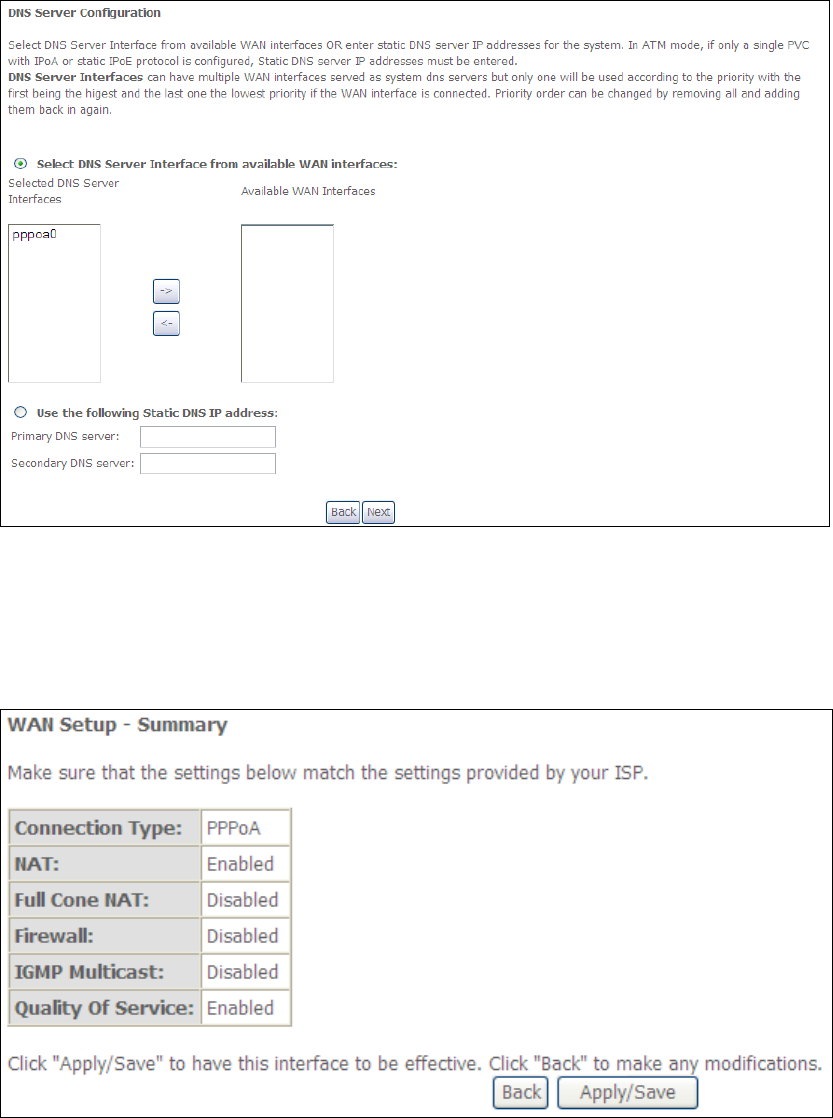
Select DNS Server Interface from available WAN interfaces OR enter static DNS
server IP addresses for the system. In ATM mode, if only a single PVC with IPoA or
static IPoE protocol is configured, Static DNS server IP addresses must be entered.
Click Next to continue or click Back to return to the previous step.
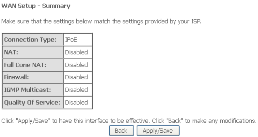
STEP 5: The WAN Setup - Summary screen shows a preview of the WAN service
you have configured. Check these settings and click Apply/Save if they
are correct, or click Back to modify them.
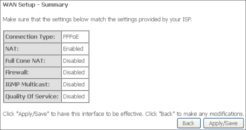
162
After clicking Apply/Save, the new service should appear on the main screen.
To activate it you must reboot. Go to Management Reboot and click Reboot.
163
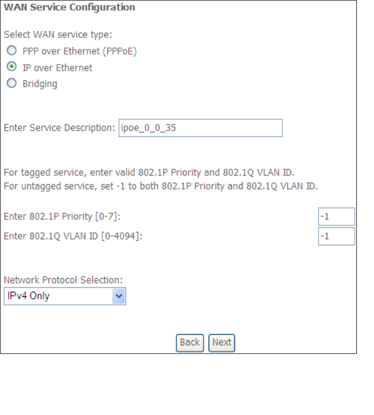
E2.2 IP over ETHERNET (IPoE)
STEP 1: *Select the IP over Ethernet radio button and click Next.
*
For tagged service, enter valid 802.1P Priority and 802.1Q VLAN ID.
For untagged service, set -1 to both 802.1P Priority and 802.1Q VLAN ID.
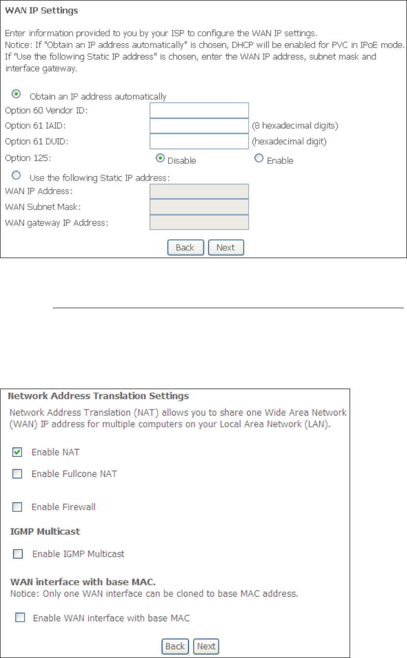
STEP 2: The WAN IP settings screen provides access to the DHCP server settings.
You can select the Obtain an IP address automatically radio button to
enable DHCP (use the DHCP Options only if necessary). However, if you
prefer, you can instead use the Static IP address method to assign WAN
IP address, Subnet Mask and Default Gateway manually.
164
NOTE: If IPv6 networking is enabled, an additional set of instructions, radio
buttons, and text entry boxes will appear at the bottom of the screen.
These configuration options are quite similar to those for IPv4 networks.
Click Next to continue or click Back to return to the previous step.
STEP 3: This screen provides access to NAT, Firewall and IGMP Multicast settings.
Enable each by selecting the appropriate checkbox . Click Next to
continue or click Back to return to the previous step.
165
ENABLE NAT
If the LAN is configured with a private IP address, the user should select this
checkbox . The NAT submenu will appear in the Advanced Setup menu after
reboot. On the other hand, if a private IP address is not used on the LAN side (i.e.
the LAN side is using a public IP), this checkbox should not be selected, so as to
free up system resources for improved performance.
ENABLE FULLCONE NAT
This option becomes available when NAT is enabled. Known as one-to-one NAT, all
requests from the same internal IP address and port are mapped to the same
external IP address and port. An external host can send a packet to the internal host,
by sending a packet to the mapped external address.
ENABLE FIREWALL
If this checkbox is selected, the Security submenu will be displayed on the
Advanced Setup menu after reboot. If firewall is not necessary, this checkbox
should not be selected so as to free up system resources for better performance.
ENABLE IGMP MULTICAST
Tick the checkbox to enable Internet Group Membership Protocol (IGMP)
multicast. IGMP is a protocol used by IPv4 hosts to report their multicast group
memberships to any neighboring multicast routers.
Enable WAN interface with base MAC
Enable this option to use the router’s base MAC address as the MAC address for this
WAN interface.
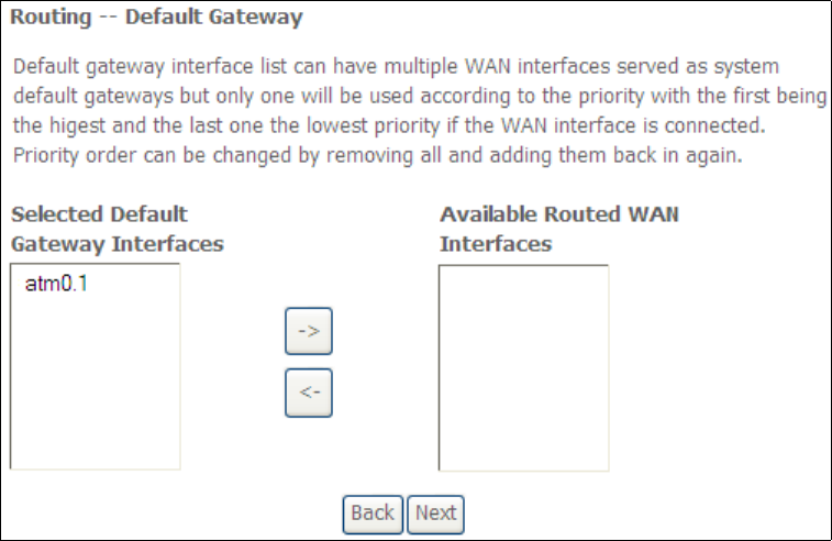
STEP 4: To choose an interface to be the default gateway.
Click Next to continue or click Back to return to the previous step.
STEP 5: Select DNS Server Interface from available WAN interfaces OR enter static
DNS server IP addresses for the system. In ATM mode, if only a single PVC with IPoA
166
or static IPoE protocol is configured, Static DNS server IP addresses must be
entered.
If IPv6 is enabled, an additional set of options will be shown.
IPv6: Select the configured WAN interface for IPv6 DNS server information OR enter
the static IPv6 DNS server Addresses.
Note that selecting a WAN interface for IPv6 DNS server will enable DHCPv6 Client
on that interface.
Click Next to continue or click Back to return to the previous step.
167
STEP 6: The WAN Setup - Summary screen shows a preview of the WAN service
you have configured. Check these settings and click Apply/Save if they
are correct, or click Back to modify them.
After clicking Apply/Save, the new service should appear on the main screen.
To activate it you must reboot. Go to Management Reboot and click Reboot.
168
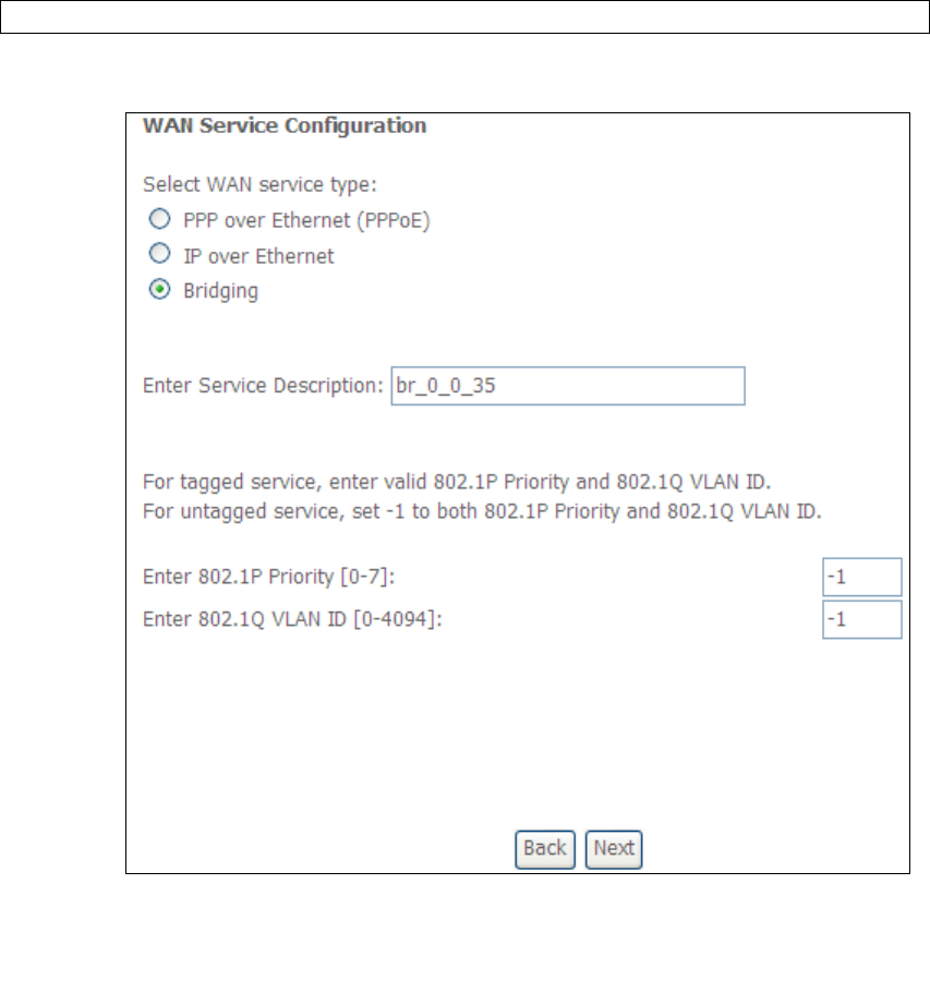
E2.3 Bridging
NOTE: This connection type is not available on the Ethernet WAN interface.
STEP 1: *Select the Bridging radio button and click Next.
*
For tagged service, enter valid 802.1P Priority and 802.1Q VLAN ID.
For untagged service, set -1 to both 802.1P Priority and 802.1Q VLAN ID.
STEP 2: The WAN Setup - Summary screen shows a preview of the WAN service
you have configured. Check these settings and click Apply/Save if they
are correct, or click Back to return to the previous screen.
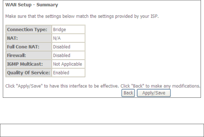
169
After clicking Apply/Save, the new service should appear on the main screen.
To activate it you must reboot. Go to Management Reboot and click Reboot.
NOTE: If this bridge connection is your only WAN service, the AR-5312u will be
inaccessible for remote management or technical support from the WAN.
170
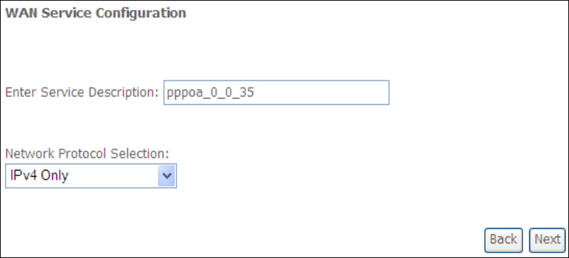
E2.4 PPP over ATM (PPPoA)
STEP 1: Click Next to continue.
STEP 2: On the next screen, enter the PPP settings as provided by your ISP.
Click Next to continue or click Back to return to the previous step.
171
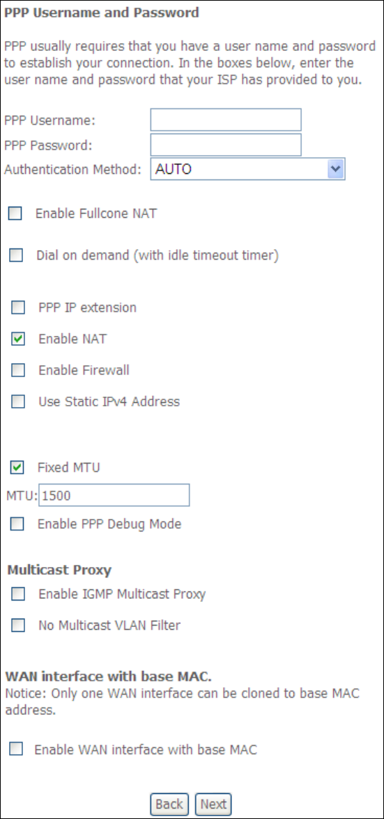
PPP SETTINGS
The PPP username and password are dependent on the requirements of the ISP.
The user name can be a maximum of 256 characters and the password a maximum
of 32 characters in length. (Authentication Method: AUTO, PAP, CHAP, or MSCHAP.)

172
KEEP ALIVE INTERVAL
This option configures the interval between each PPP LCP request and the amount of
time to wait for the PPP server to reply to the LCP request. If the time expired on all
requests, the current PPP session would be dropped.
ENABLE FULLCONE NAT
This option becomes available when NAT is enabled. Known as one-to-one NAT, all
requests from the same internal IP address and port are mapped to the same
external IP address and port. An external host can send a packet to the internal host,
by sending a packet to the mapped external address.
DIAL ON DEMAND
The AR-5312u can be configured to disconnect if there is no activity for a period of
time by selecting the Dial on demand checkbox . You must also enter an
inactivity timeout period in the range of 1 to 4320 minutes.
PPP IP EXTENSION
The PPP IP Extension is a special feature deployed by some service providers.
Unless your service provider specifically requires this setup, do not select it.
PPP IP Extension does the following:
• Allows only one PC on the LAN.
• Disables NAT and Firewall.
• The device becomes the default gateway and DNS server to the PC
through DHCP using the LAN interface IP address.
• The device extends the IP subnet at the remote service provider to the
LAN PC. i.e. the PC becomes a host belonging to the same IP subnet.
• The device bridges the IP packets between WAN and LAN ports, unless
the packet is addressed to the device’s LAN IP address.
• The public IP address assigned by the remote side using the PPP/IPCP
protocol is actually not used on the WAN PPP interface. Instead, it is
forwarded to the PC LAN interface through DHCP. Only one PC on the
LAN can be connected to the remote, since the DHCP server within the
device has only a single IP address to assign to a LAN device.
ENABLE NAT
If the LAN is configured with a private IP address, the user should select this
checkbox . The NAT submenu will appear in the Advanced Setup menu after reboot.
On the other hand, if a private IP address is not used on the LAN side (i.e. the LAN
side is using a public IP), this checkbox should not be selected to free up system
resources for better performance.
ENABLE FIREWALL
If this checkbox is selected, the Security submenu will be displayed on the
Advanced Setup menu after reboot. If firewall is not necessary, this checkbox
should not be selected to free up system resources for better performance.
173
USE STATIC IPv4 ADDRESS
Unless your service provider specially requires it, do not select this checkbox . If
selected, enter the static IP address in the IP Address field. Also, don’t forget to
adjust the IP configuration to Static IP Mode as described in section 3.2.
Fixed MTU
Fixed Maximum Transmission Unit. The size (in bytes) of largest protocol data unit
which the layer can pass onwards. This value is 1500 for PPPoA.
ENABLE PPP DEBUG MODE
When this option is selected, the system will put more PPP connection information
into the system log. This is for debugging errors and not for normal usage.
ENABLE IGMP MULTICAST PROXY
Tick the checkbox to enable Internet Group Membership Protocol (IGMP)
multicast. This protocol is used by IPv4 hosts to report their multicast group
memberships to any neighboring multicast routers.
NO MULTICAST VLAN FILTER
Tick the checkbox to Enable/Disable multicast VLAN filter.
Enable WAN interface with base MAC
Enable this option to use the router’s base MAC address as the MAC address for this
WAN interface.
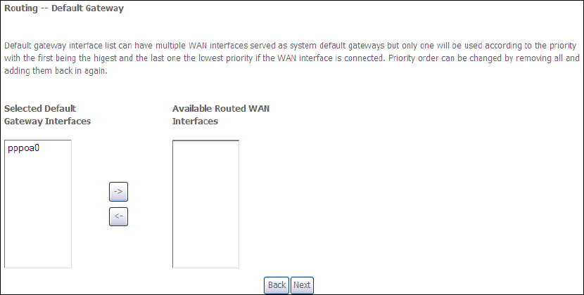
STEP 3: Choose an interface to be the default gateway.
Click Next to continue or click Back to return to the previous step.
STEP 4: Choose an interface to be the default gateway.
174
Click Next to continue or click Back to return to the previous step.
STEP 5: The WAN Setup - Summary screen shows a preview of the WAN service
you have configured. Check these settings and click Apply/Save if they are correct,
or click Back to modify them.
After clicking Apply/Save, the new service should appear on the main screen.
To activate it you must reboot. Go to Management Reboot and click Reboot.
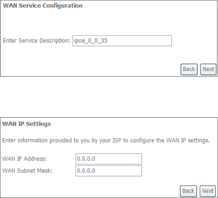
175
E2.5 IP over ATM (IPoA)
STEP 1: Click Next to continue.
STEP 2: Enter the WAN IP settings provided by your ISP. Click Next to continue.
STEP 3: This screen provides access to NAT, Firewall and IGMP Multicast settings.
Enable each by selecting the appropriate checkbox . Click Next to
continue or click Back to return to the previous step.
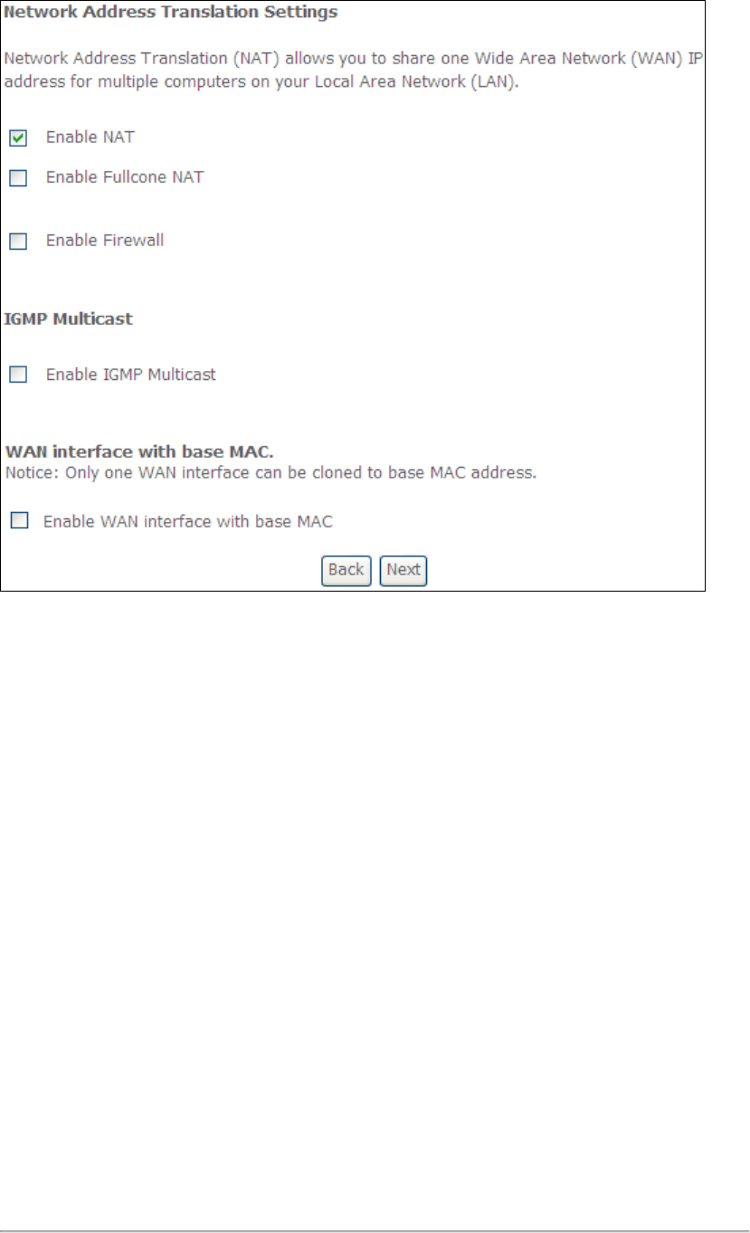
176
ENABLE NAT
If the LAN is configured with a private IP address, the user should select this
checkbox . The NAT submenu will appear in the Advanced Setup menu after
reboot. On the other hand, if a private IP address is not used on the LAN side (i.e.
the LAN side is using a public IP), this checkbox should not be selected, so as to
free up system resources for improved performance.
ENABLE FULLCONE NAT
This option becomes available when NAT is enabled. Known as one-to-one NAT, all
requests from the same internal IP address and port are mapped to the same
external IP address and port. An external host can send a packet to the internal host
by sending a packet to the mapped external address.
ENABLE FIREWALL
If this checkbox is selected, the Security submenu will be displayed on the
Advanced Setup menu after reboot. If firewall is not necessary, this checkbox
should not be selected so as to free up system resources for better performance.
ENABLE IGMP MULTICAST
Tick the checkbox to enable Internet Group Membership Protocol (IGMP)
multicast. IGMP is a protocol used by IPv4 hosts to report their multicast group
memberships to any neighboring multicast routers.
Enable WAN interface with base MAC
Enable this option to use the router’s base MAC address as the MAC address for this
WAN interface.
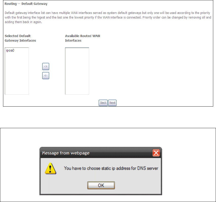
177
STEP 4: Choose an interface to be the default gateway.
Click Next to continue or click Back to return to the previous step.
NOTE: If the DHCP server is not enabled on another WAN interface then the
following notification will be shown before the next screen.
STEP 5: Choose an interface to be the default gateway.
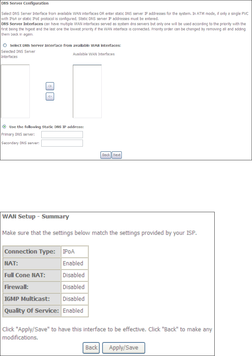
178
Click Next to continue or click Back to return to the previous step.
STEP 6: The WAN Setup - Summary screen shows a preview of the WAN service
you have configured. Check these settings and click Apply/Save if they
are correct, or click Back to modify them.
After clicking Apply/Save, the new service should appear on the main screen.
To activate it you must reboot. Go to Management Reboot and click Reboot.
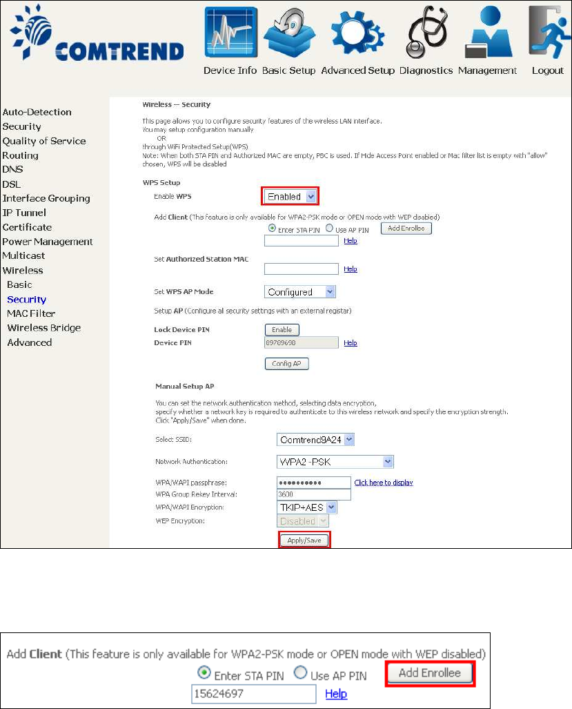
179
Appendix F - WPS OPERATION
This Section shows the basic AP WPS Operation procedure.
F1 Add Enrollee with Pin Method
1) Select Enabled from the Enable WPS dropdown menu.
2) Click the Apply/Save button at the bottom of the screen.
3) When the screen refreshes select the Radio button “Enter STA Pin”
4) Input Pin from Enrollee Station (15624697 in this example)
5) Click “Add Enrollee”
4) Operate Station to start WPS Adding Enrollee.
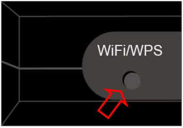
180
F2 Add Enrollee with PBC Method
1) Press the WiFi/WPS button on the front of the router to activate WPS PBC
operation.
2) Operate Station (your dongle for example) to start WPS Adding Enrollee.
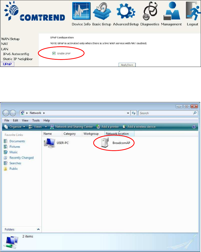
181
F3 – Configure WPS External Registrar
Follow these steps to add an external registrar using the web user interface (WUI)
on a personal computer running the Windows 7 operating system:
Step 1: Enable UPnP on the Advanced Setup LAN screen in the WUI.
NOTE: A PVC must exist to see this option.
Step 2: Open the Network folder and look for the BroadcomAP icon.
Step 3: On the Wireless Security screen, enable WSC by selecting Enabled
from the drop down list box and set the WPS AP Mode to Unconfigured.

182
Step 4: Click the Apply/Save button at the bottom of the screen. The screen
will go blank while the router applies the new Wireless settings.
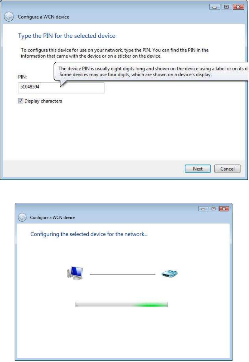
183
Step 5: Now return to the Network folder and click the BroadcomAP icon. A
dialog box will appear asking for the Device PIN number. Enter the
Device PIN as shown on the Wireless Security screen. Click Next.
Step 6: Windows 7 will attempt to configure the wireless security settings.
Step 7: If successful, the security settings will match those in Windows 7.
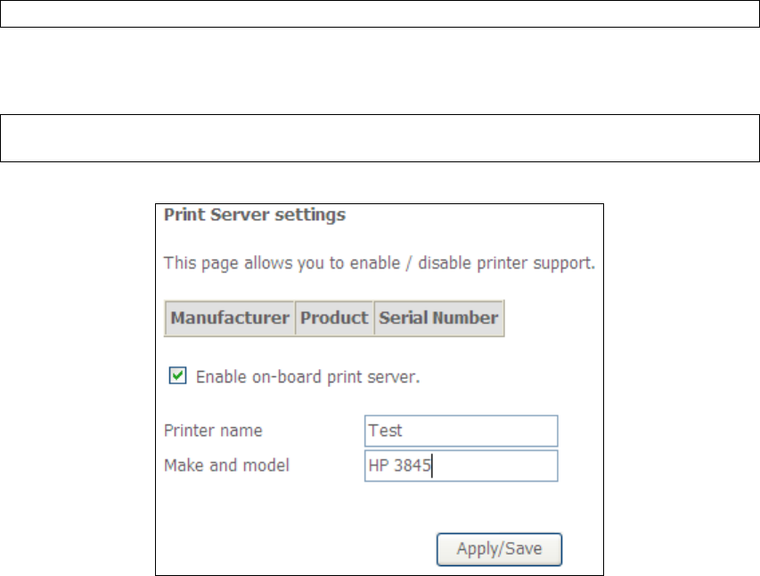
184
Appendix G - Printer Server
These steps explain the procedure for enabling the Printer Server.
NOTE: This function only applies to models with an USB host port.
STEP 1: Enable Print Server from Web User Interface. Select Enable on-board
print server checkbox and enter Printer name and Make and model
NOTE: The Printer name can be any text string up to 40 characters.
The Make and model can be any text string up to 128 characters.
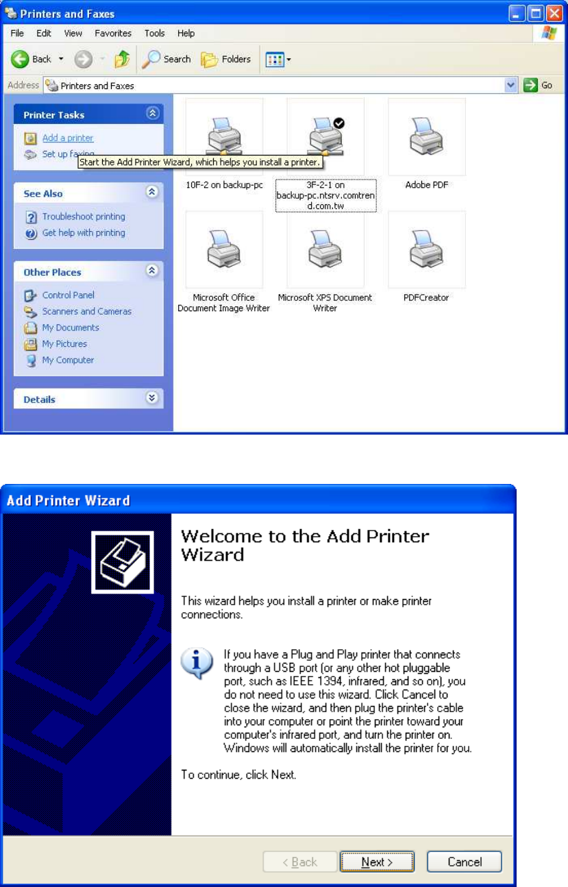
185
STEP 2: Go to the Printers and Faxes application in the Control Panel and
select the Add a printer function (as located on the side menu below).
STEP 3: Click Next to continue when you see the dialog box below.
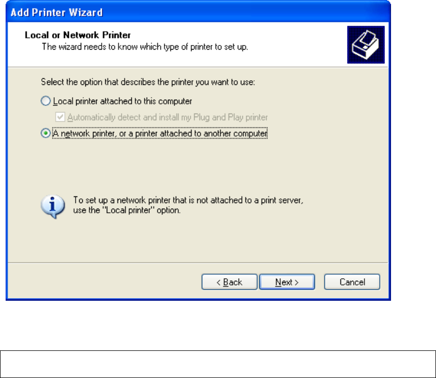
186
STEP 4: Select Network Printer and click Next.
STEP 5: Select Connect to a printer on the Internet and enter your printer link.
(e.g. http://192.168.1.1:631/printers/hp3845) and click Next.
NOTE: The printer name must be the same name entered in the ADSL modem
WEB UI “printer server setting” as in step 1.
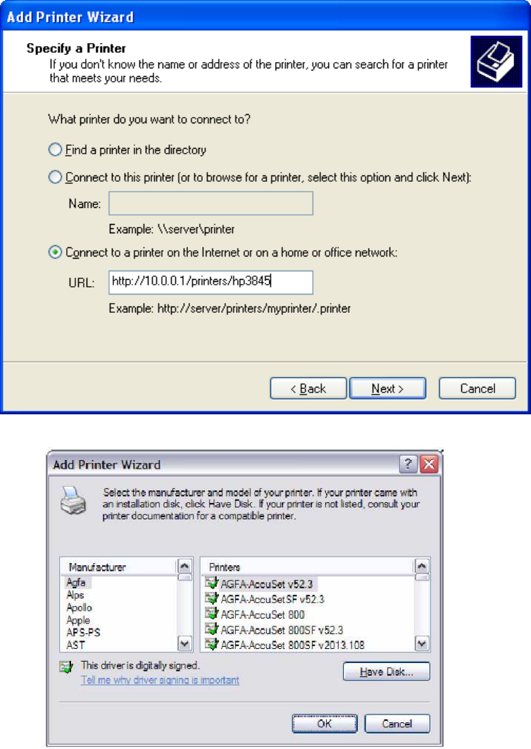
187
STEP 6: Click Have Disk and insert the printer driver CD.
STEP 7: Select driver file directory on CD-ROM and click OK.
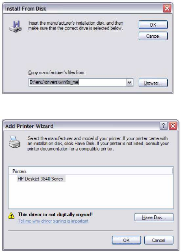
188
STEP 8: Once the printer name appears, click OK.
STEP 9: Choose Yes or No for default printer setting and click Next.
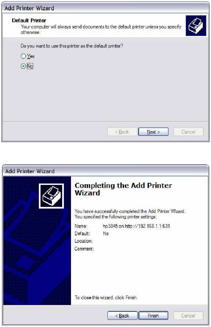
189
STEP 10: Click Finish.
190
STEP 11: Check the status of printer from Windows Control Panel, printer window.
Status should show as Ready.
FCC Part 15.21
CAUTION:
Any changes or modifications not expressly approved by the party responsible for
compliance could void the user's authority to operate the equipment.
FCC Part 2.1091
RF exposure warning
Ʉ
This equipment must be installed and operated in accordance with provided
instructions and the antenna(s) used for this transmitter must be installed to
provide a separation distance of at least 20 cm from all persons and must not be
co-located or operating in conjunction with any other antenna or transmitter.
End-users and installers must be provided with antenna installation instructions and
transmitter operating conditions for satisfying RF exposure compliance.