Comtrend AR-5381U Wireless ADSL2+ router User Manual UM AR 5381u A2 0
Comtrend Corporation Wireless ADSL2+ router UM AR 5381u A2 0
UserManual.wiki
>
Comtrend
>
AR-5381U User Manual
>
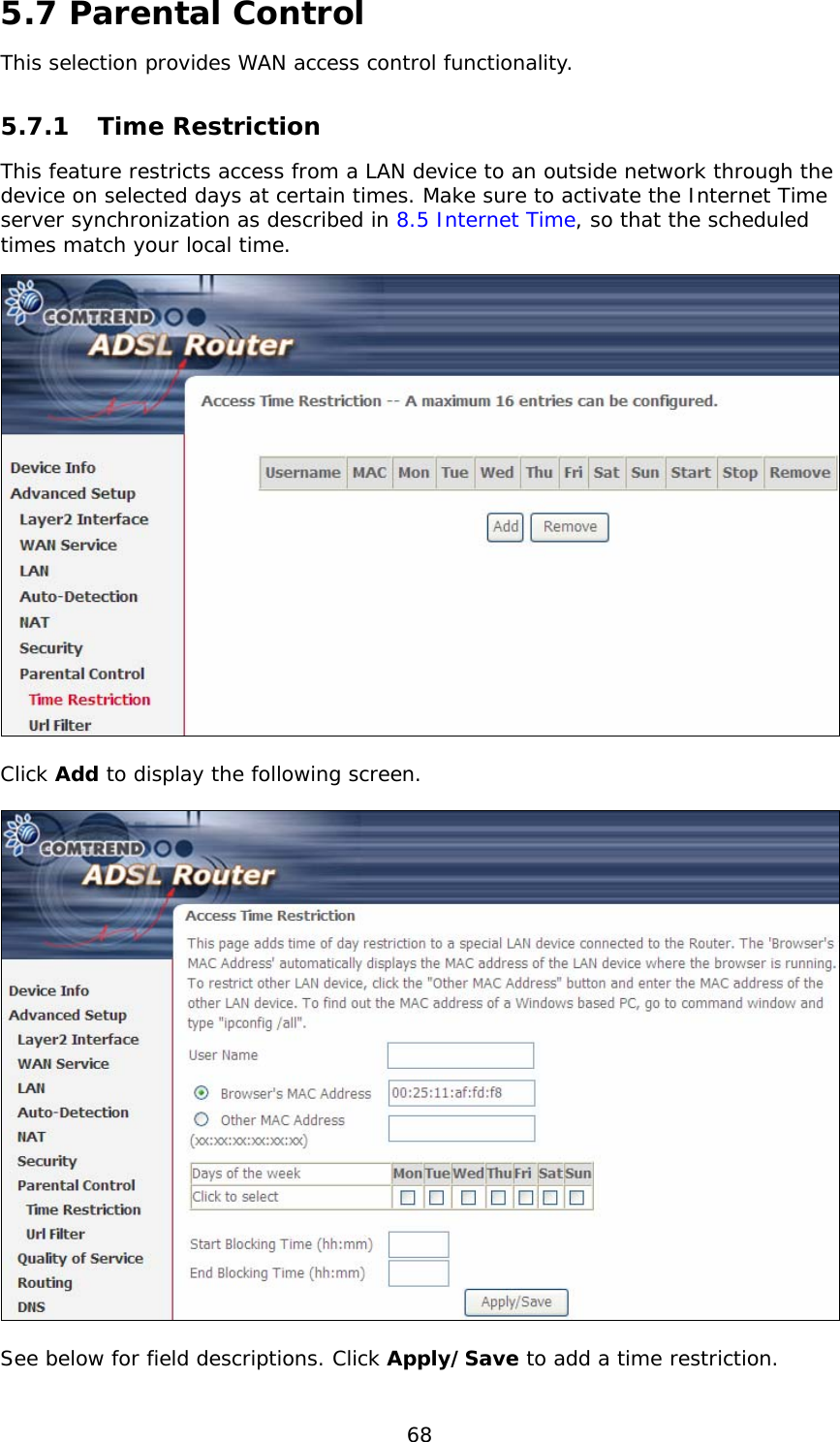
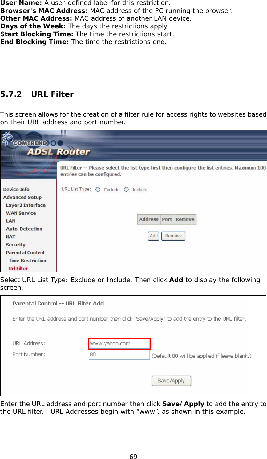
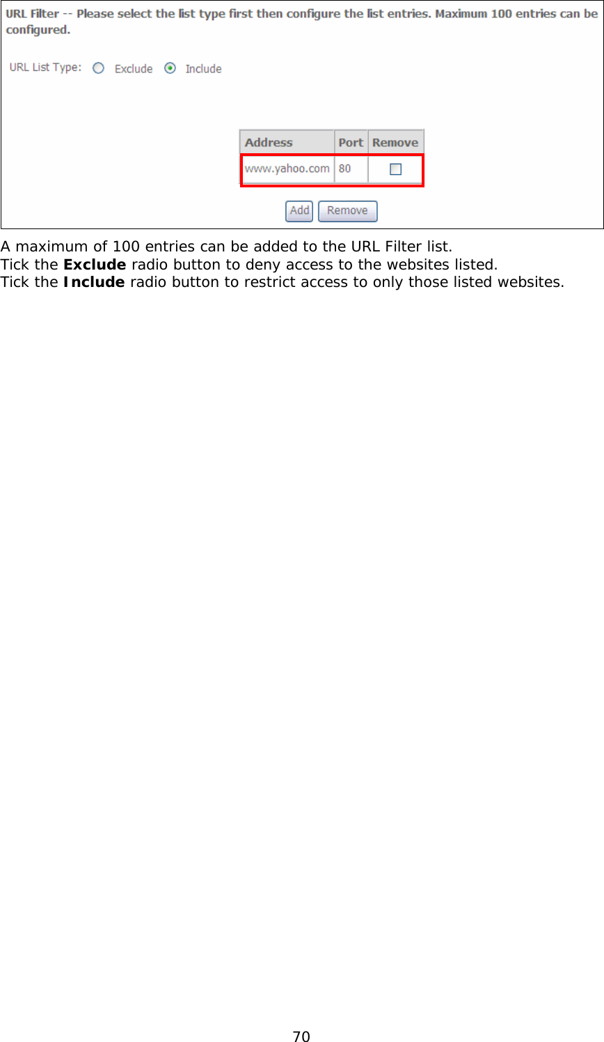
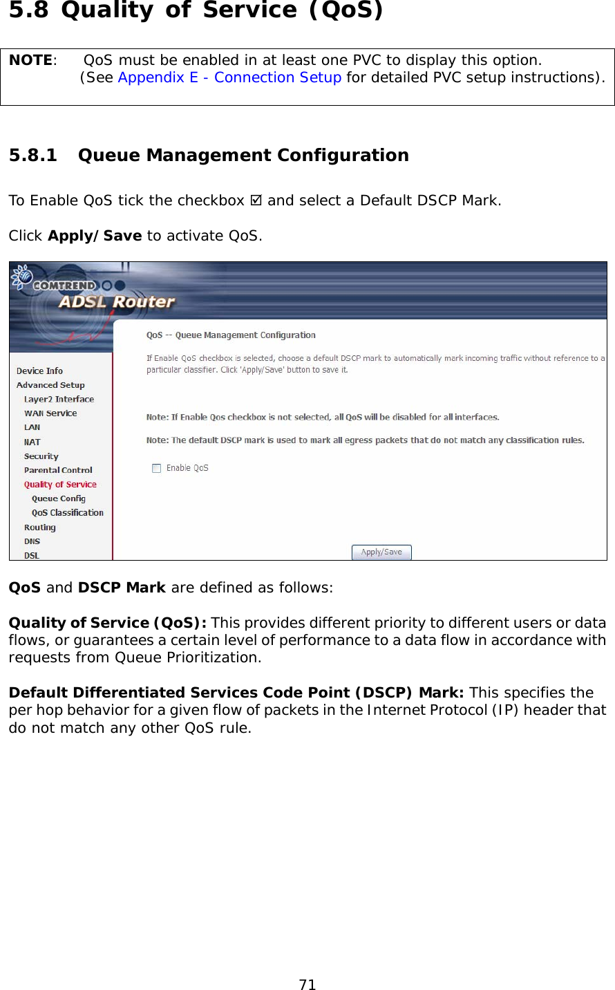
5.Users manual-1
Contents
1.
5.Users manual-1
2.
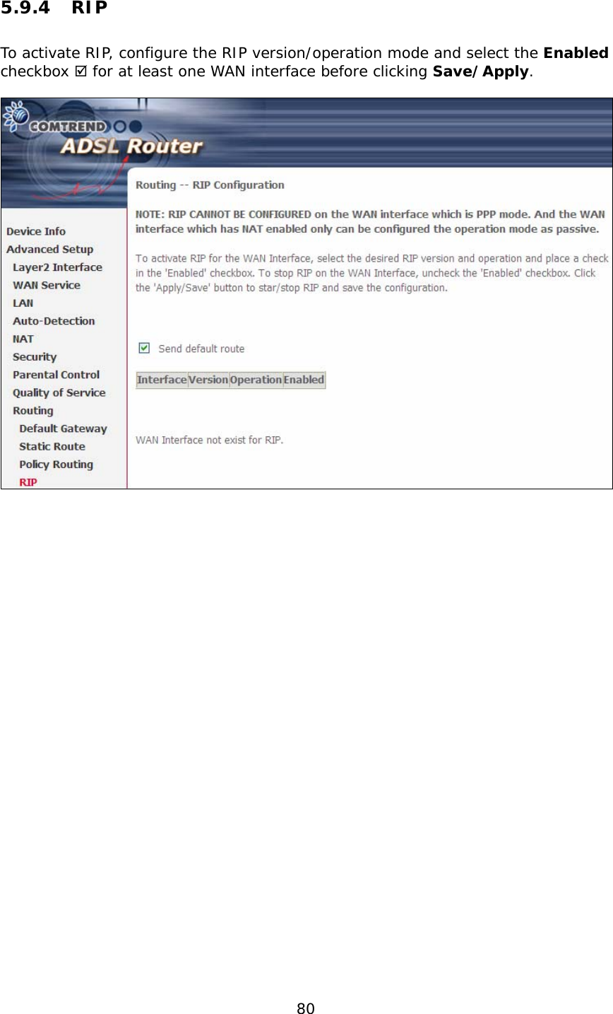
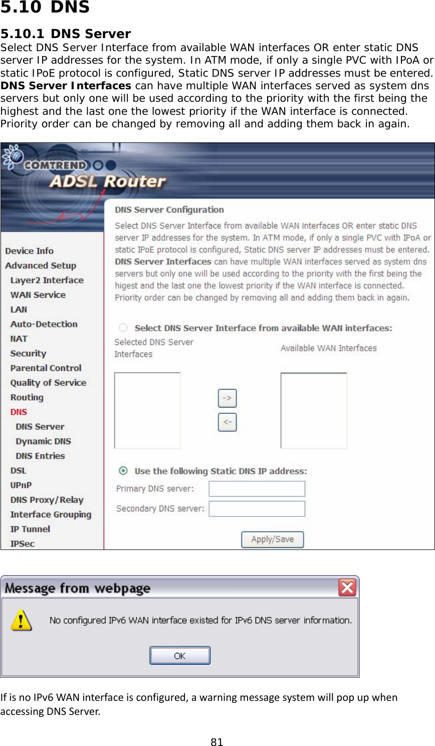
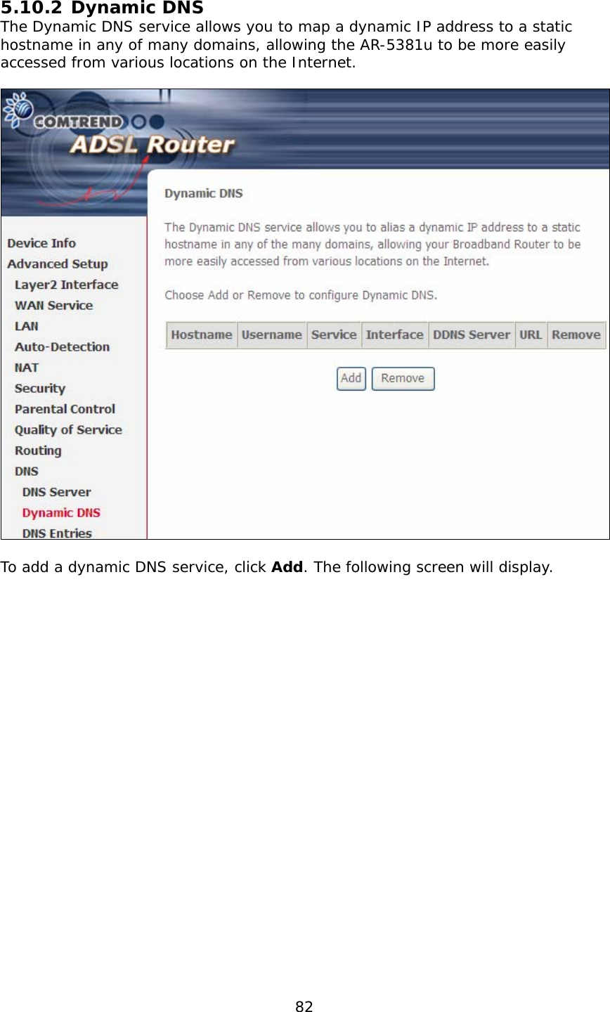
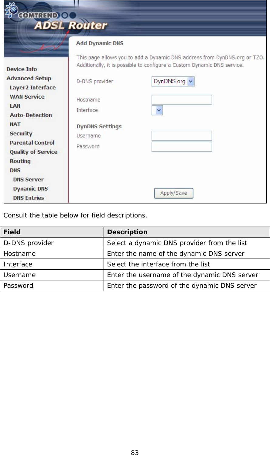
5.Users manual-2 R2
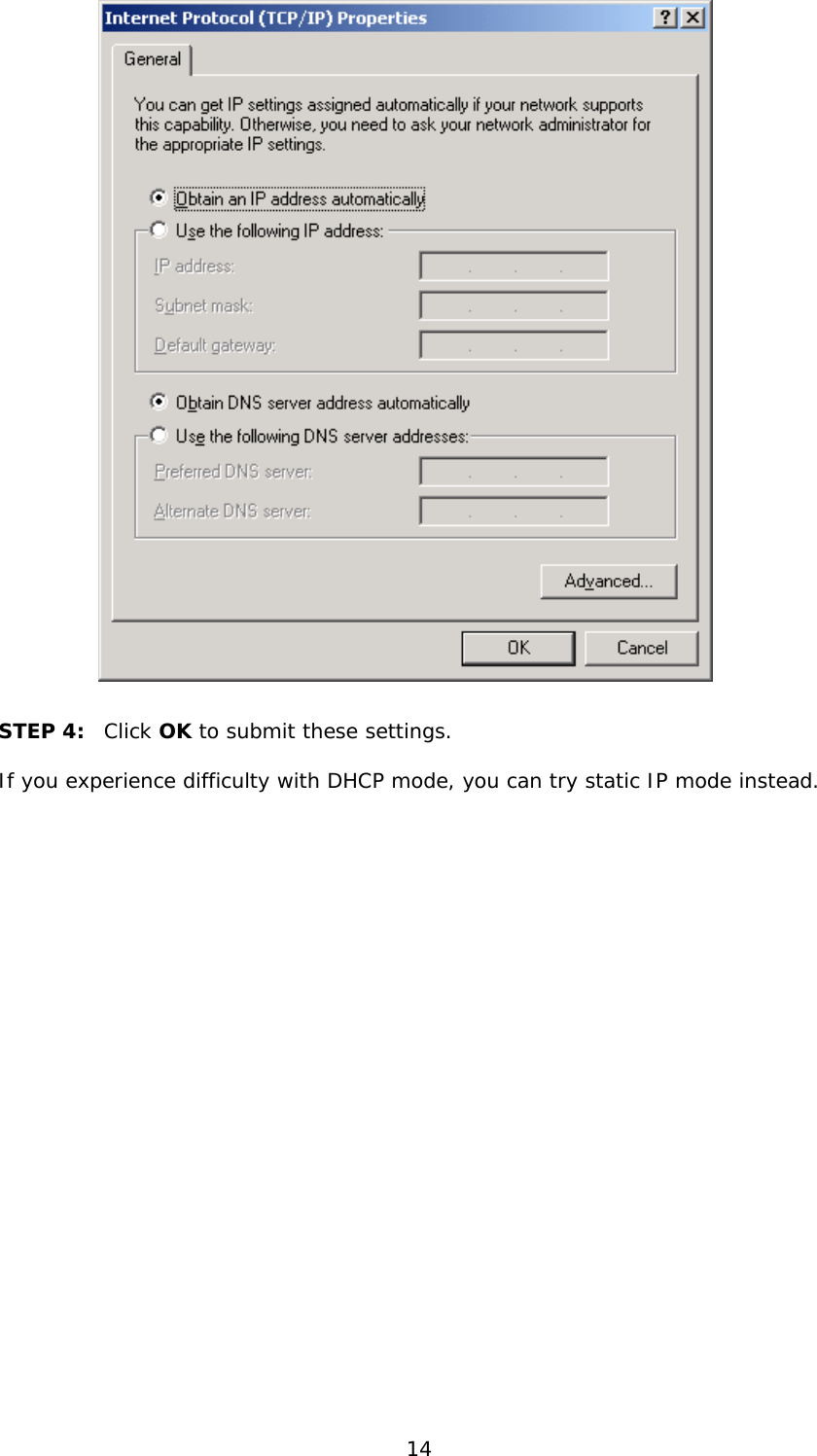
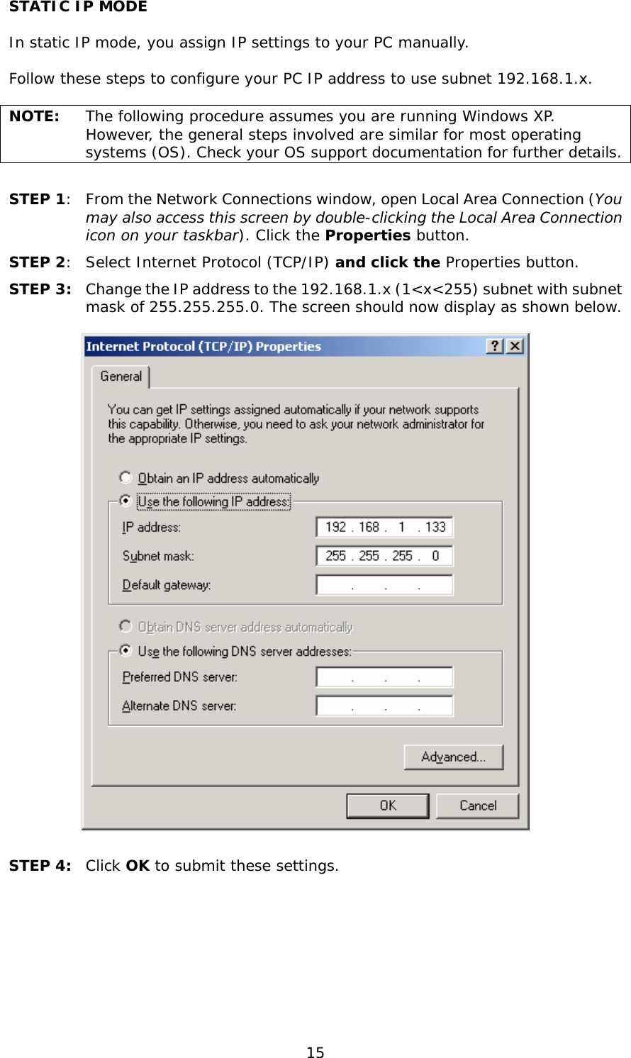
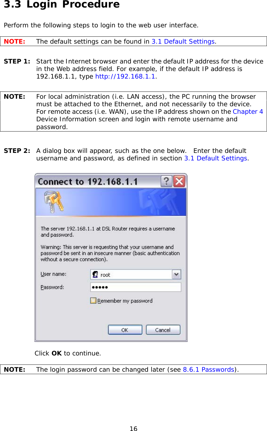
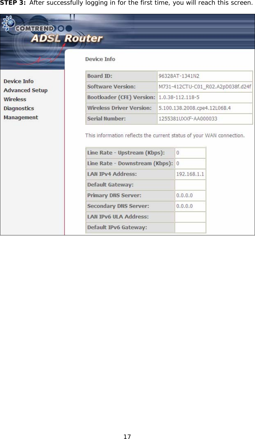
5.Users manual-1
Navigation menu
Upload a User Manual
Namespaces
Wiki Guide
HTML
PDF
Info
Views
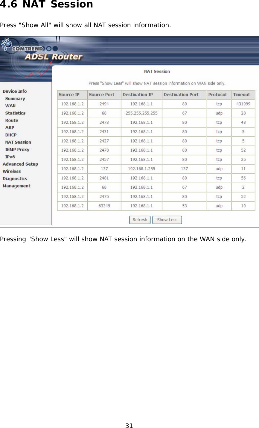
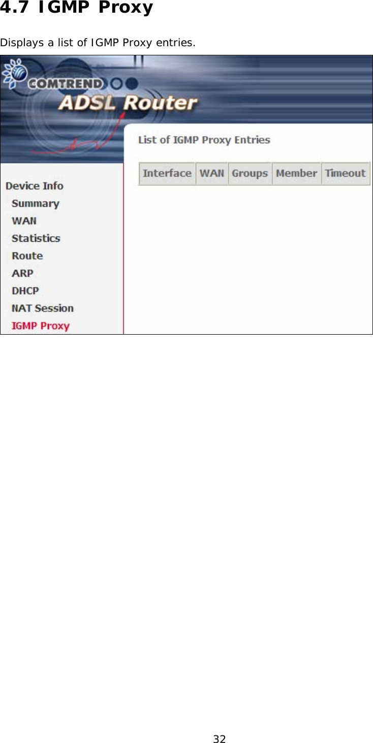
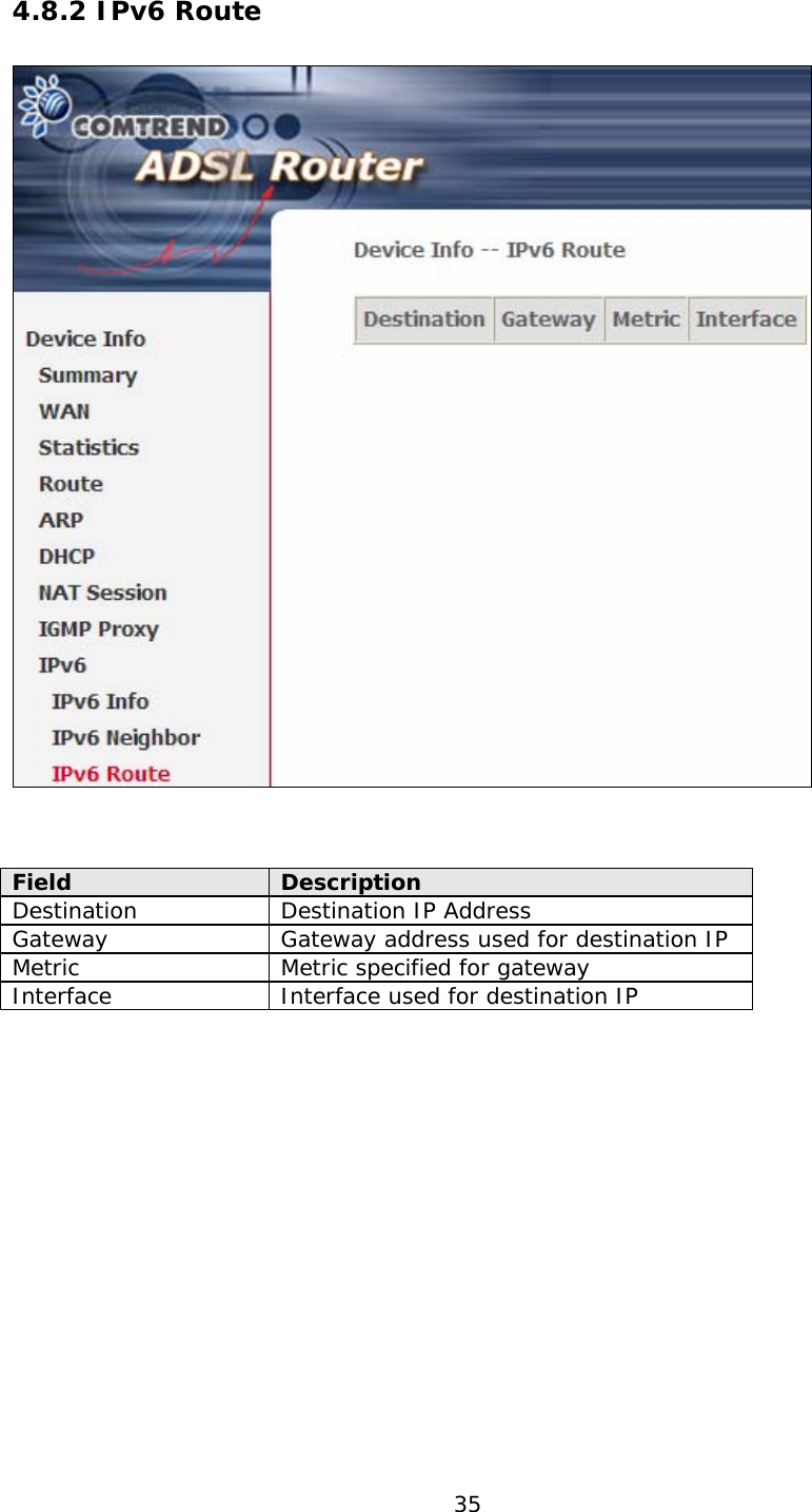
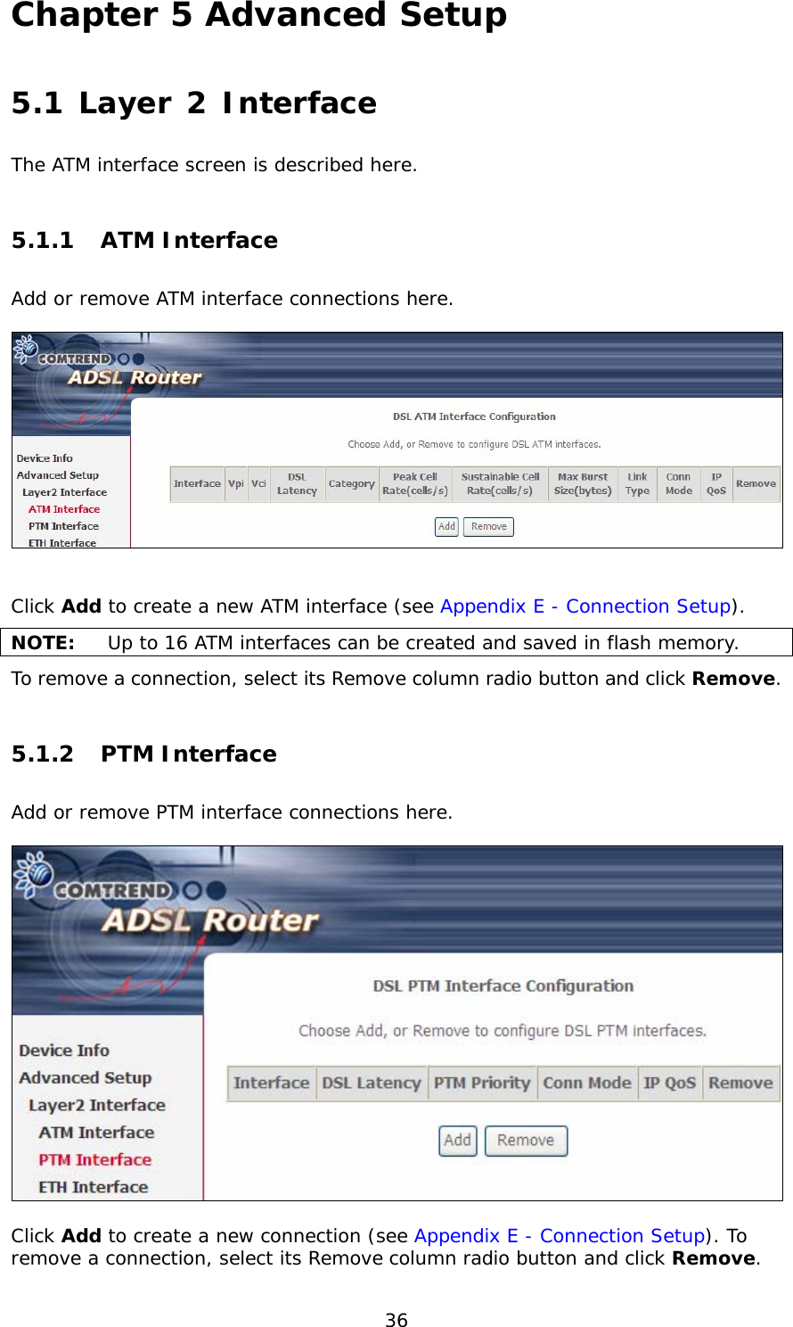
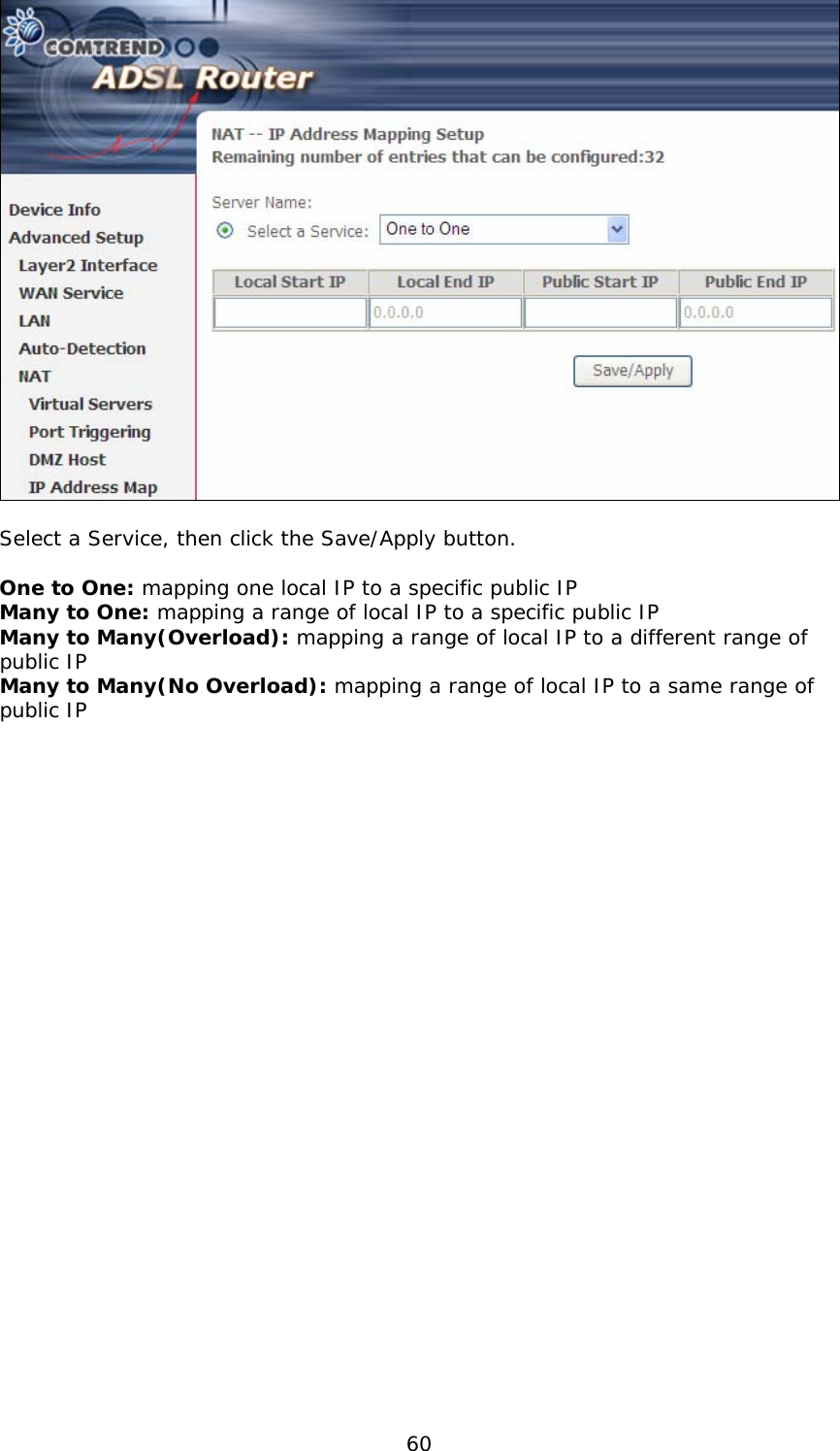
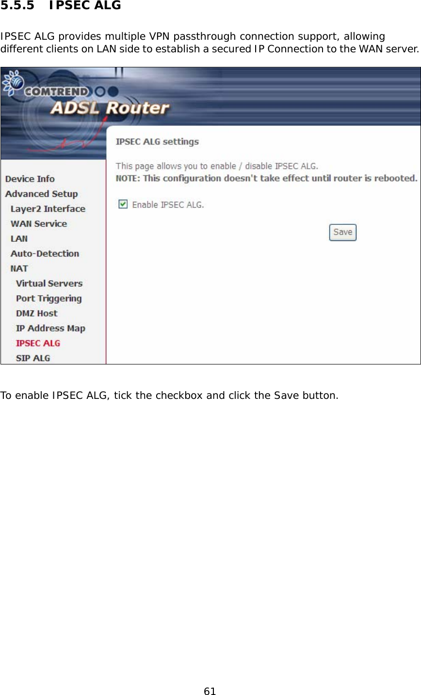
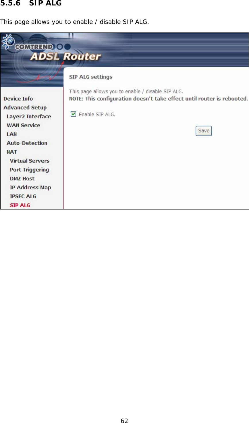
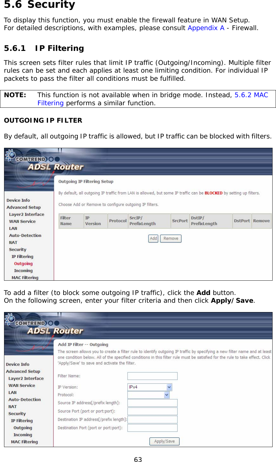
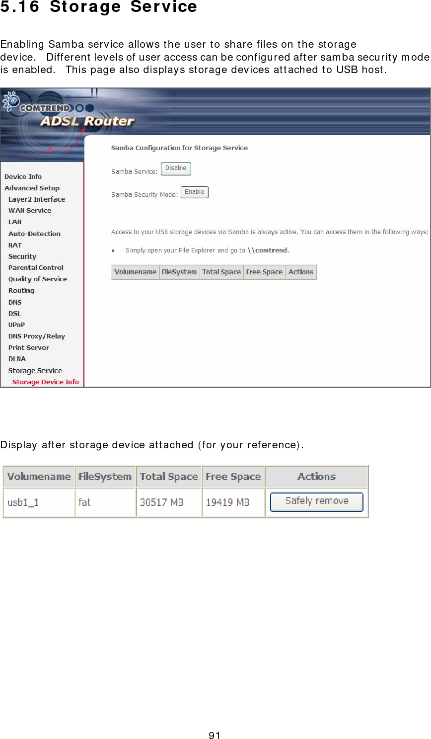
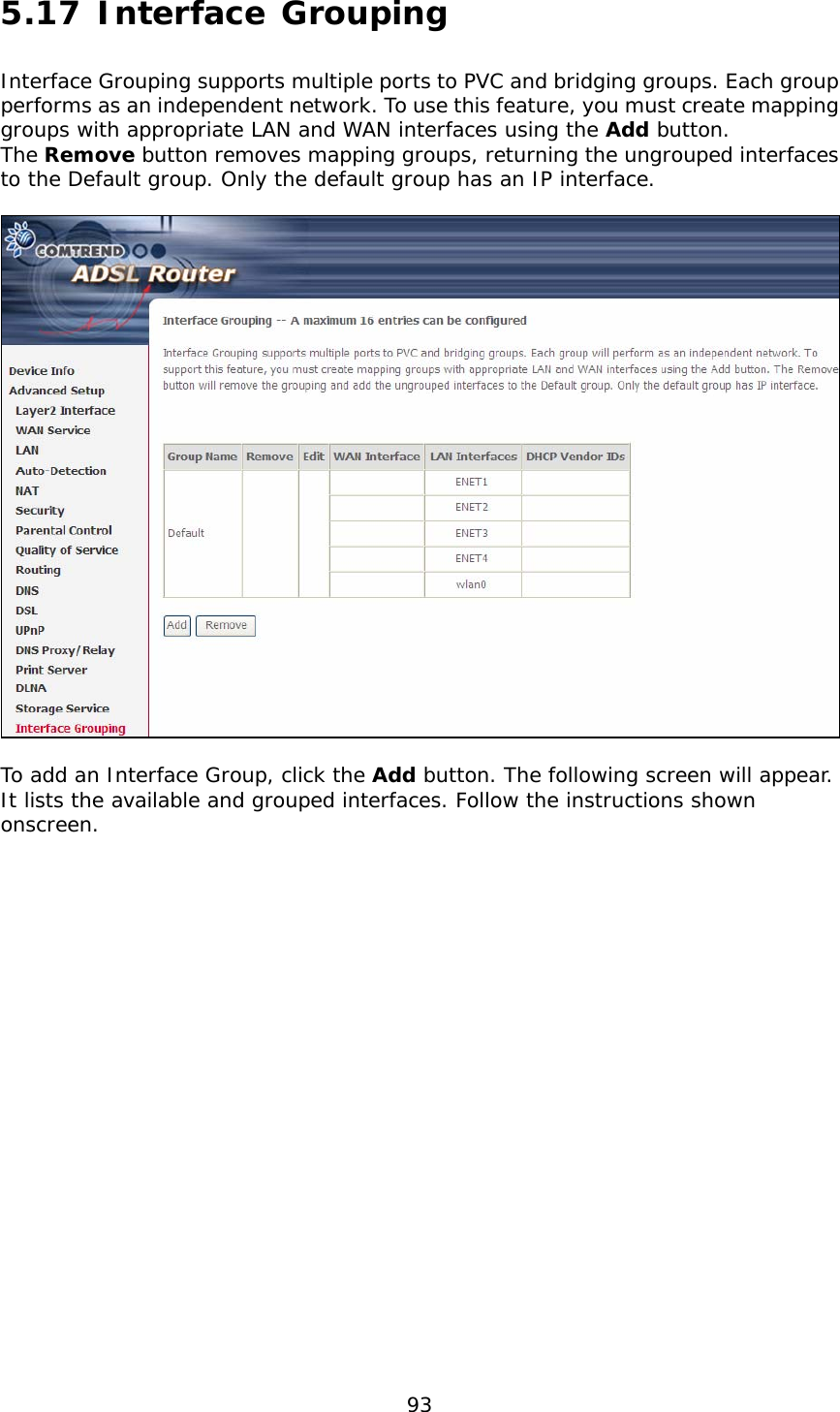
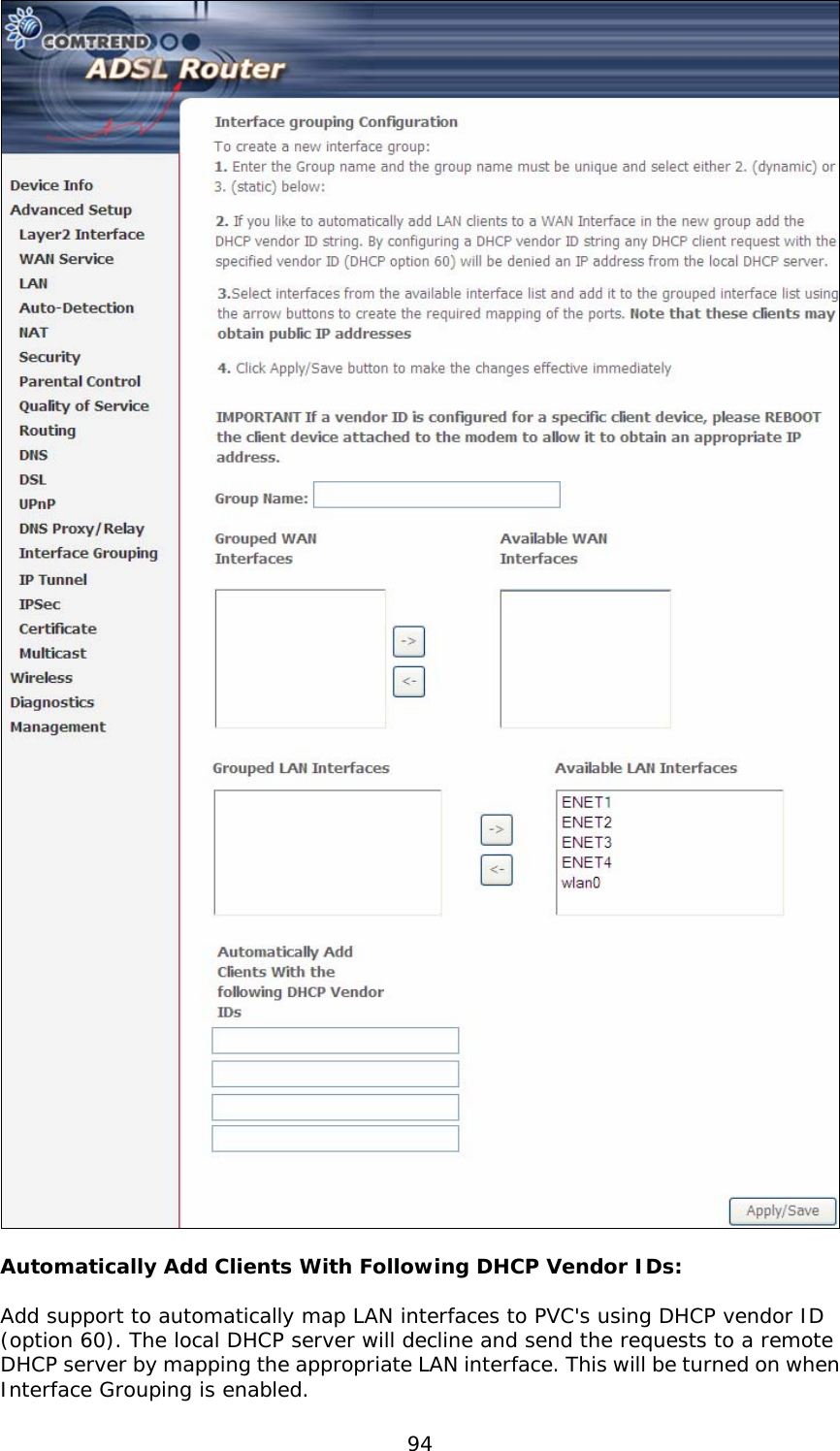
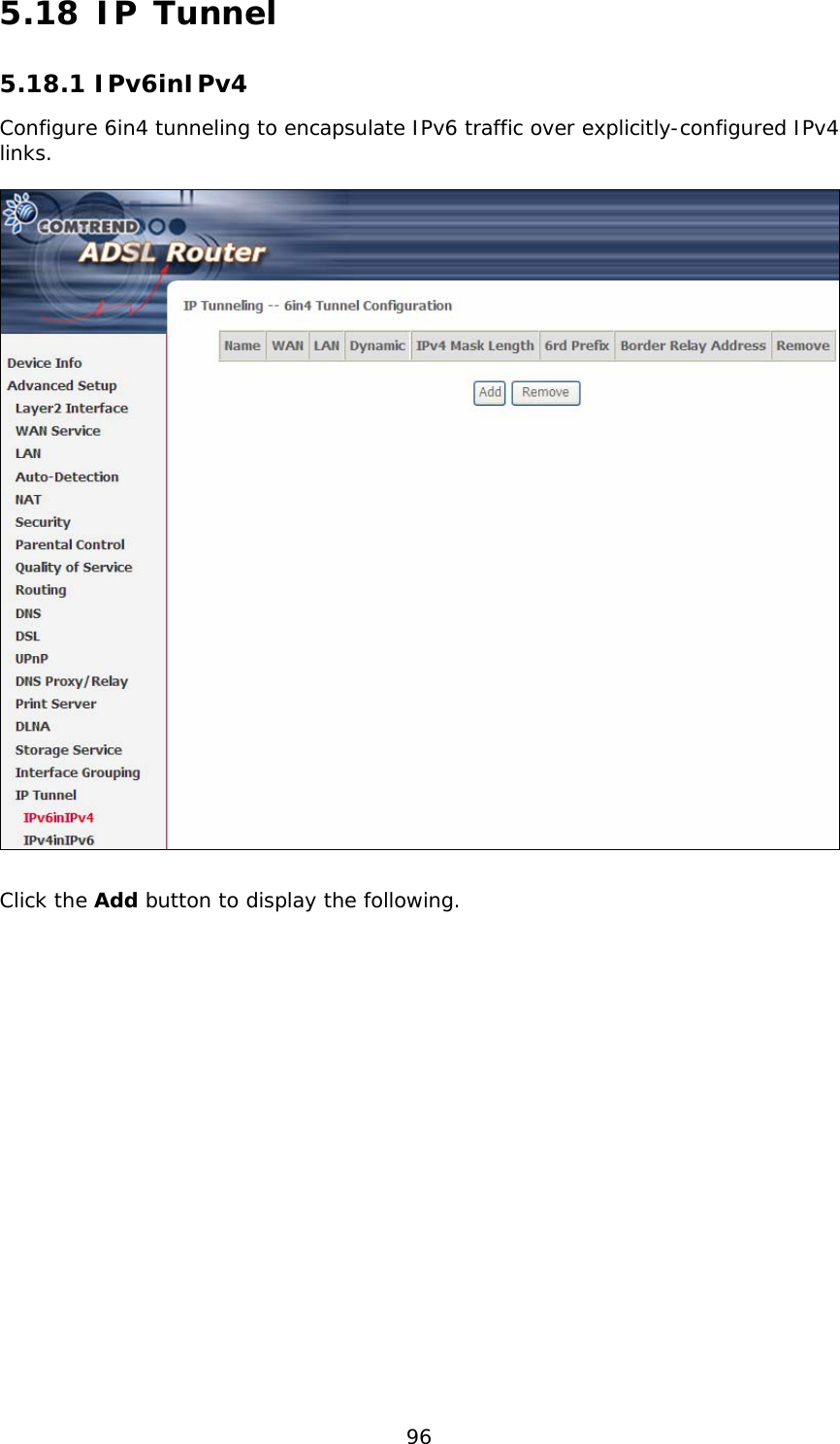
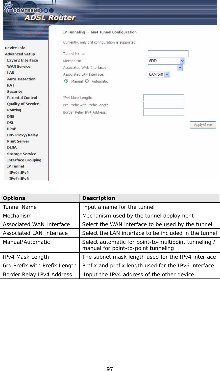
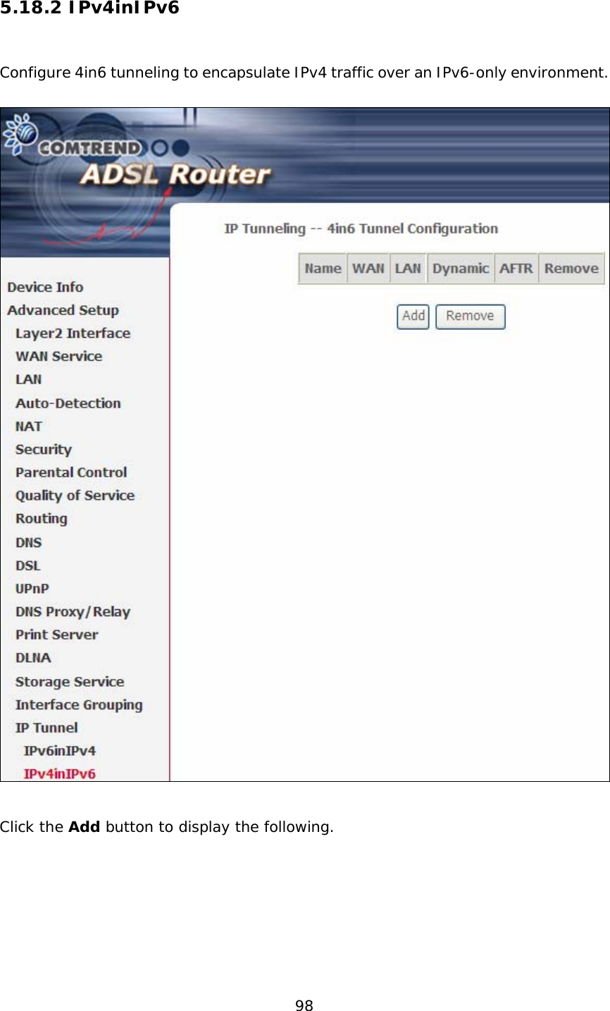
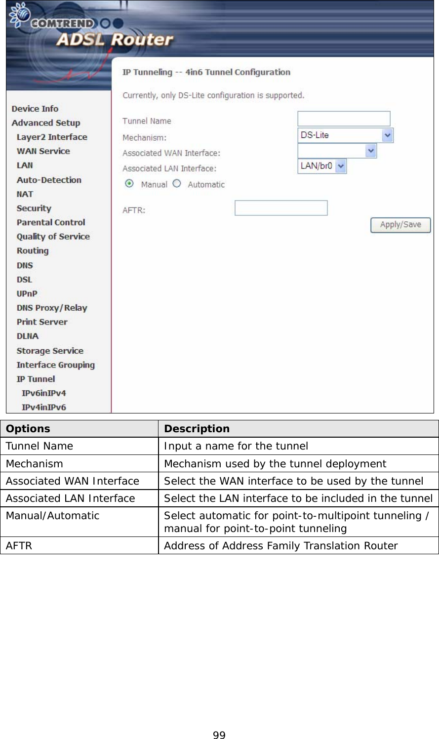
User Manual
Discussion / Help
Navigation