Comtrend COMTREND5836 Wireless Extender User Manual WAP 5836 QIG 14 3X10 20120524
Comtrend Corporation Wireless Extender WAP 5836 QIG 14 3X10 20120524
Comtrend >
(WAP-5836)UserMan
WAP-5836
Wireless Extender
QUICK
INSTALLATION
GUIDE
Introduction
Easy Installation
Step 1 - Power connection
This Quick Installation Guide will help you to quickly and easily install your
Wireless Extender devices by performing the few simple steps described
below. Before you begin, check that you have:
• One WAP-5836 Wireless Extender
• One CAT5 Ethernet Cable
• One Power Adapter
• One Quick Installation Guide
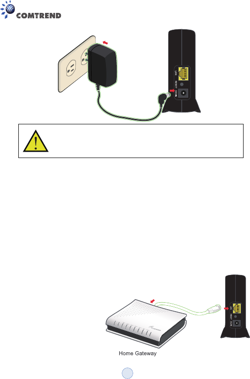
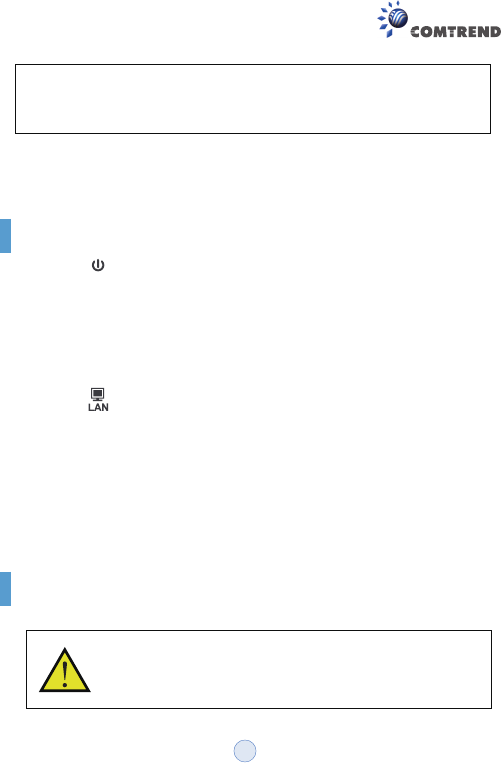
Plug in the power adapter included in your package, and connect it to the
WAP-5836 device.
1
Step 2 - Placement and connections
A. Setting an AP device
Using a power supply with different voltage rating than the one
included with the WAP-5836 device may cause damage and
void the warranty for this product.
1. Place one WAP-5836 device on an easily accessible surface near the
Home Gateway or Router. Make sure the GW or Router is powered on and
active.
2. Plug one end of the Ethernet cable into the LAN port of the Home Gateway
device and the other end into the Ethernet port of the WAP-5836.
3. Ensure that the DHCP
Server functionality on your
Home Gateway or Router is
enabled. The WAP-5836
device that gets a DHCP IP
Address will be automatically
set in Access Point (AP)
mode for a simplified setup
process.
2
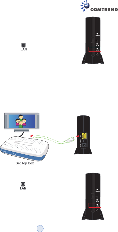
B. Setting a Client device
Make sure that the LED on the WAP-5836
is flashing blue.
1. Place another WAP-5836 device on an easily accessible surface near the
set top box. Plug one end of the Ethernet cable into the LAN port of the Set
Top Box and the other end into the Ethernet port of the WAP-5836.
2. Since the STB will not issue an IP address to the WAP-5836, it will
automatically be set to Client mode.
Make sure that the LED on the WAP-5836
Client is flashing blue. For best wireless performance,
place the devices on a shelf or other elevated
location and away from large metallic objects.
3
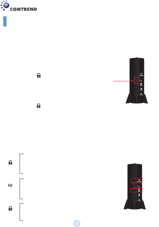
Pairing
Step 1. Pair the devices:
For initial pairing, it is recommended that you place the WAP-5836 AP and
Client devices within the same room. Once paired, they can then be put in
their desired locations.
Press the WPS button on the “AP” front panel for
3-5 seconds and release it.
The LED will begin flashing blue.
Press the WPS button on the “Client” for
3-5 seconds and release it.
The LED will begin flashing blue.
WPS
WPS
NOTE – The WPS buttons can be pressed in any order as long as
they are pressed within 2 minutes of each other.
Step 2. Wait for the pairing process to complete by watching the LEDs on
the devices:
• The LEDs will flash blue for a few seconds after
pressing the WPS button for both AP & Client.
• The LEDs will change to solid blue after
successful pairing and turn off two minutes later.
• The Wireless LEDs will then be solid blue.
• The Client wireless LED could be solid amber
when the association is not able to receive a
high quality HD stream.
If pairing is unsuccessful:
• The LEDs will flash blue for two minutes and
then turn off.
WPS
WPS
Wireless
WPS Button
4
Congratulations! You have finished installing your new Wireless Extender
devices. To test your connectivity, turn on the TV and set top box, and then
watch any available TV channel.
Note: To add additional WAP-5836 Clients to your network, you will need to
perform the pairing procedures as explained above.
Troubleshooting
• The LED is not on
• The LED is not on
Make sure that:
• The power cord is connected to the device, and that the power
adapter is properly connected to a functioning power outlet.
• You are using the power adapter that was supplied with the product.
Make sure that:
• The LAN cable connectors are securely plugged in at the WAP-5836
and at the network device (gateway, modem or set top box).
• The connected network device is turned on.
• You are using the correct cable type for your Ethernet equipment,
which is at least UTP CAT5 with RJ45 connectors.
Power
Advanced Settings via the Web-based User Interface
The instructions below are for users who have adequate
networking knowledge. Users are not encouraged to configure
the following settings because this may cause connectivity
issues.
5
Step 1.
Step 2.
Note: • If you are connecting to the WAP-5836 directly from a PC, be
sure to set a static IP in the same range as the AP or Client unit
(e.g. 10.0.0.25) to access the Web Configuration page.
• If the WAP-5836 is connected to a Gateway or Router that has a
DHCP server, it will automatically get an IP address from that
device. Be sure to check your Gateway or Router to see what IP
address was given to the WAP-5836 units and use that to log in
to the Web Configuration page.
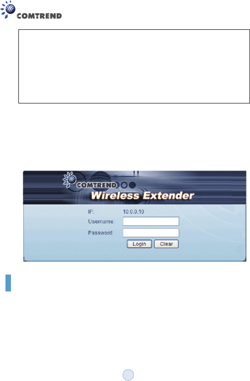
Log into the WAP-5836 web GUI through a browser such as IE
with either the IP address the device was given by your DHCP
server, or the default IP address of 10.0.0.10 for devices that
have yet to be paired.
Type default Username: root and Password: 12345
Advanced Troubleshooting
• The WPS function is not working
Make sure that:
• The devices are in either AP or Client mode.
• The WPS function is activated on the AP device.
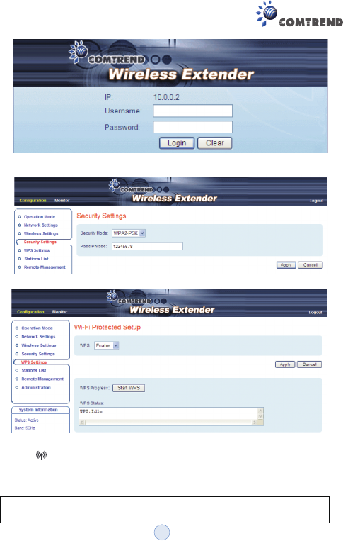
a. Enter into the WAP-5836 Web GUI
b. Type default Username: root and Password: 12345
6
Wireless
• Complete the pairing procedures as described in the Pairing section.
• The LED is not on
• Make sure that you have completed a successful pairing procedure as
described in the Pairing section.
FOR MORE HELP: If you have further questions or require personal
assistance, please contact your equipment provider.
c. Change the security mode to WPA2-PSK in Security Settings by
selecting it in the drop-down menu.
d. Enable WPS in WPS settings and press the “Apply” button.
7

WAP-5836_QIG_V1.1
This device complies with part 15 of the FCC Rules. Operation is subject to the following two
conditions:
(1) This device may not cause harmful interference, and (2) this device must accept any
interference received, including interference that may cause undesired operation.
The operation frequency of the device is in the 5150-5250 MHz band is for indoor use only.
This equipment has been tested and found to comply with the limits for a Class B digital device,
pursuant to part 15 of the FCC Rules. These limits are designed to provide reasonable protection
against harmful interference in a residential installation. This equipment generates, uses and can
radiate radio frequency energy and, if not installed and used in accordance with the instructions,
may cause harmful interference to radio communications. However, there is no guarantee that
interference will not occur in a particular installation. If this equipment does cause harmful
interference to radio or television reception, which can be determined by turning the equipment off
and on, the user is encouraged to try to correct the interference by one or more of the following
measures:
• Reorient or relocate the receiving antenna.
• Increase the separation between the equipment and receiver.
• Connect the equipment into an outlet on a circuit different from that to which the
receiver is connected.
• Consult the dealer or an experienced radio/ TV technician for help.
CAUTION:
Any changes or modifications not expressly approved by the grantee of this device could void the
user's authority to operate the equipment.
RF exposure warning :
This equipment must be installed and operated in accordance with provided instructions and the
antenna(s) used for this transmitter must be installed to provide a separation distance of at least 20
cm from all persons and must not be co-located or operating in conjunction with any other antenna
or transmitter. End-users and installers must be provided with antenna installation instructions and
transmitter operating conditions for satisfying RF exposure compliance.
8