ConectiSys HNET50BS8 ConectiSys H-Net Automatic Meter Reader User Manual 8CBase RevB
ConectiSys Corporation ConectiSys H-Net Automatic Meter Reader 8CBase RevB
Manual

Page 1 of 7
ConectiSys H-Net? 5.0 8Ch Basestation
Installation and Operations Manual
Sections:
I. FCC Warning, Compliance and Radio Frequency Exposure Statements
II. Introduction and Basestation Description
III. Basestation Mounting and Wiring.
IV. Basestation Software Configuration.
V. Reference Figures.
I. FCC Warning, Compliance and Radio Frequency Exposure Statements
FCC Warning
The users manual or instruction manual for an intentional or unintentional
radiator shall caution the user that changes or modifications not expressly
approved by the party responsible for compliance (ConectiSys) could void the
user's authority to operate the equipment.
FCC Compliance Statement
This device complies with Part 15 of the FCC Rules. Operation is subjected to
the following two conditions 1) this device may not cause harmful interference
and 2) this device must accept any interference received, including interference
that may cause undesired operation.
FCC Radio Frequency Exposure Statement
The H-Net? 5.0 8Ch Base Station has been evaluated under FCC Bulletin OET
65 and found compliant to the requirements as set forth in CFR 47 Sections
2.1091, 2.1093, and 15.247 (b) (4) addressing RF Exposure from radio frequency
devices. The radiated output power of the H-Net? 5.0 8Ch Base Station is well
below the FCC radio frequency exposure limits. Nevertheless, this device should
be installed in such a manner that the potential for human contact during normal
operation is minimized. To ensure RF exposure compliance, in order to comply
with RF exposure limits established in the ANSI C95.1 standards, the distance
between the antenna and the user should not be less than 20 cm.

Page 2 of 7
II. Introduction and Basestation Description
Introduction: The H-Net? radio system has been developed by ConectiSys
Corp. as an Automatic Meter Reading (AMR) solution for residential and
commercial energy markets. H-Net? utilizes a proprietary protocol for two-way
communication using a wireless, tower-less network. The H-Net? 5.0 Eight
Channel Basestation is a controlling hub for an H-Net? 5.0 radio system
network. The basestation provides a central point for data collection from
individual meter units, synchronizing and communicating with individual meters in
a TDMA scheme. The eight channel basestation is designed to receive data
from up to eight meter units simultaneously time in the basestation’s receive
sequence. The design provides a solid foundation for future iterations of
basestations that will integrate additional receivers.
The basestation consists of a PC/104 computer, Compact Flash drive,
AC/DC converter, DC/DC converter, battery back-up system, surge protectors
and 8 H-Net? 5.0 radios (one of which has been modified to be the transmitter
unit, while the other seven will only receive). The power system is comprised of
a 120VAC to 12VDC converter with a 12VDC-battery backup and a 12VDC to
5VDC/3.3VDC converter to power the PC/104 and radios respectively. The radio
system is composed of eight radios, each composed of two PCB assemblies
(controller module and RF module), a multiplexing board and an omnidirectional
vertically mounted, horizontally polarized antenna. The controller and RF
modules interface together via PCB mounted headers. The controllers are
interfaced to the PC/104 via RS232 serial lines. The antenna is weather sealed
and mounted on the top of the basestation. The basestation is housed within an
environmentally sealed enclosure meeting the following standards:
UL 508 Type 3R, 4, 12 and 13
CSA Type 3R, 4, 12 and 13 Complies with
??NEMA Type 3R, 4, 12 and 13
??JIC EGP-1-1967 unless marked¹
??IEC 529, IP66

Page 3 of 7
III. Installation and wiring:
WARNING: Failure to wire as instructed may cause damage to device or
connected equipment or personal injury. To be installed or checked by an
electrician or qualified person only.
Note:
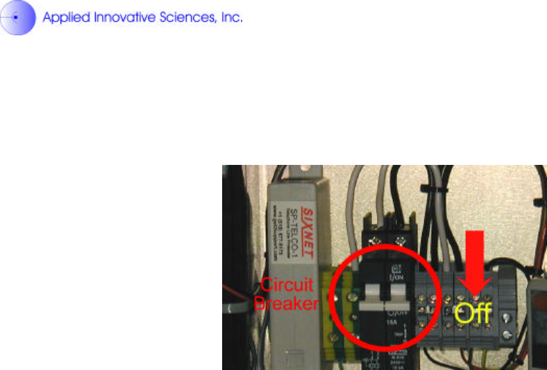
??Before basestation installation has begun, the basestation should checked to
ensure the AC circuit breaker and battery backup switches are in the off
position. (See Figures 1 and 5).
??All wiring devices must be installed and used in accordance with applicable
listings, ratings, and codes. References to National Electrical Code are
applicable to installations in the United States only.
1. Basestation Mounting:
a. The H-Net? Eight-channel basestation comes configured to be
mounted on a vertical 2 ¾ inch diameter pole.
b. Mounting pole must be sturdy enough to support 50 pounds against
maximum local wind conditions.
c. Basestation mounting height will be determined by a qualified
technician after a local site survey has been conducted.
d. Basestation is mounted to pole by two 360° Clamping U-Bolts.
(See Figure 2).
2. Basestation Wiring
a. 120VAC and modem wiring are to be run through ½ inch flexible
metallic conduit designed for such applications.
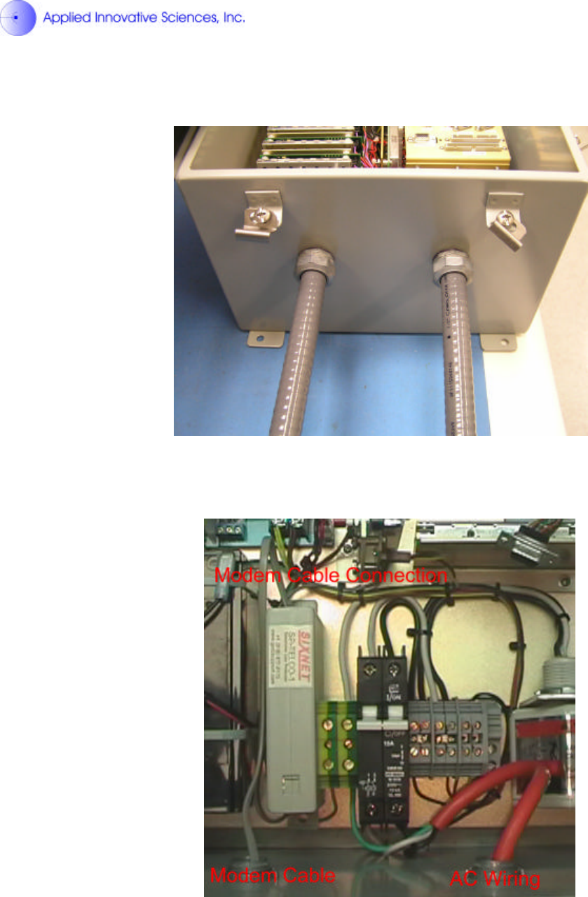
b. Conduit is connected to bottom of basestation through two Liqua-
Seal connectors. (See Figure 3).
c. Modem cable should be run through left conduit and 120VAC
through the right.
d. Modem cable should be a standard RJ-11 telephone cord
connected to a direct telephone line.
e. Modem cable is plugged into topside of telephone line surge
protector (See Figure 4).
f. 120VAC wiring is connected circuit breaker and ground block.
Wiring should be white wire (neutral) connected to circuit breaker
left terminal, black wire (hot) connected to circuit breaker right
terminal and green wire (ground) connected to the green and
yellow DIN rail grounding block (See Figure 4).

Page 4 of 7
IV. Software Configuration:
H-Net? 5.0 Eight Channel Basestation software needs to be configured for each
installation.
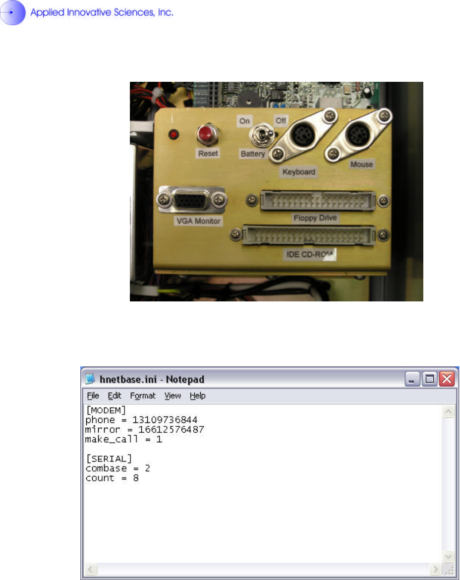
1. After the basestation has been properly installed connect a PS/2 mouse
and keyboard to the indicated connectors in the basestation.
2. Connect a standard VGA PC monitor to the DB15 monitor connector. (See
Figure 5).
3. Power up monitor.
4. Power up basestation by flipping the battery back up and circuit breaker
switches to the on position.
5. After Windows has finished loading, the H-Net? software will launch
automatically. Close this program by clicking exit.
6. Open hnetbase.ini (configuration file) for editing (See Figure 6).
7. Change “phone = ###########” and “mirror = ###########” to dial-up
numbers for desired ConectiSys server.
8. Ensure “make_call = 1”.
9. “combase = #” should be set for the ComPort number of the radio module
set for transmitting, this should be set to 2 in most cases.
10. “count = #” should be set to the number of radios that will be used in the
basestation, this should be set to 8 in most cases.
11. Save and exit file.
12. Reboot basestation by shutting down Windows and turning off circuit
breaker and battery back up switches, then turning switches back on
again.
13. Basestation will dial up and connect to ConectiSys server after reboot.
Page 5 of 7
V. Reference Figures:
Figure 1 – Circuit Breaker and Battery Backup Switches
Figure 2 – Basestation Pole Mounting
Page 6 of 7
Figure 3 – Liqua-Seal Connector’s with Conduit
Figure 4 Modem cable and AC wiring
Page 7 of 7
Figure 5 – Monitor, Mouse and Keyboard Connections
Figure 6 – Software Configuration File