Connect One SM2144SMT WIFI MODULE User Manual Nano WiReach SMT DS 1 40
Connect One Ltd. WIFI MODULE Nano WiReach SMT DS 1 40
Users Manual
International:
Connect One Ltd.
20 Atir Yeda Street
Kfar Saba 44643, Israel
Phone: +972-9-766-0456
Fax: +972-9-766-0461
Email: sales@connectone.com
www.connectone.com
Pub. No. 11-4500-06, Copyright © Connect One, 2011. All rights reserved.
Nano WiReach
™
SMT
Nano WiReach™ SMT
Data Sheet
Ver. 1.40
Information provided by Connect One Ltd. is believed to be accurate and reliable.
However, Connect One assumes no responsibility for its use, nor any infringement of
patents or other rights of third parties, which may result from its use. No license is
granted by implication or otherwise under any patent rights of Connect One other than for
circuitry embodied in Connect One’s products. Connect One reserves the right to change
circuitry at any time without notice. This document is subject to change without notice.
The software described in this document is furnished under a license agreement and may
be used or copied only in accordance with the terms of such a license agreement. It is
forbidden by law to copy the software on any medium except as specifically allowed in the
license agreement. No part of this document may be reproduced or transmitted in any
form or by any means, electronic or mechanical, including but not limited to photocopying,
recording, transmitting via fax and/or modem devices, scanning, and/or information
storage and retrieval systems for any purpose without the express written consent of
Connect One.
WARNING: THE Nano WiReach SMT IS AN RF MODULE INTENDED FOR
EMBEDDING IN A HOST DEVICE. LOCAL RELEVANT RF REGULATIONS SUCH AS
ALLOWED FREQUENCIES AND USAGE IN COMMERCIAL FLIGHTS MUST BE
OBSERVED. SAFETY INSTRUCTIONS MUST BE INCLUDED IN THE MANUALS OF
THE HOST DEVICE. CONNECT ONE ASSUMES NO LIABILITY FOR CUSTOMER
FAILURE TO COMPLY WITH THESE PRECAUTIONS.
" UnderIndustryCanadaregulations,thisradiotransmittermayonlyoperateusinganantennaofatypeandmaximum(orlesser)gain
approvedforthetransmitterbyIndustryCanada.Toreducepotentialradiointerferencetootherusers,theantennatypeanditsgain
shouldbesochosenthattheequivalentisotropicallyradiatedpower(e.i.r.p.)isnotmorethanthatnecessaryforsuccessful
communication."
" Conformémentàlaréglementationd'IndustrieCanada,leprésentémetteurradiopeutfonctionneravecuneantenned'untypeet
d'ungainmaximal(ouinférieur)approuvépourl'émetteurparIndustrieCanada.Danslebutderéduirelesrisquesdebrouillage
radioélectriqueàl'intentiondesautresutilisateurs,ilfautchoisirletyped'antenneetsongaindesortequelapuissanceisotrope
rayonnéeéquivalente(p.i.r.e.)nedépassepasl'intensiténécessaireàl'établissementd'unecommunicationsatisfaisante."
" Thisradiotransmitter(SM2144N2‐BIO)hasbeenapprovedbyIndustryCanadatooperatewiththeantennatypeslisted
belowwiththemaximumpermissiblegainandrequiredantennaimpedanceforeachantennatypeindicated.Antennatypesnot
includedinthislist,havingagaingreaterthanthemaximumgainindicatedforthattype,arestrictlyprohibitedforusewiththis
device."
" Leprésentémetteurradio(SM2144N2‐BIO)aétéapprouvéparIndustrieCanadapourfonctionneraveclestypesd'antenne
énumérésci‐dessousetayantungainadmissiblemaximaletl'impédancerequisepourchaquetyped'antenne.Lestypesd'antenne
noninclusdanscetteliste,oudontlegainestsupérieuraugainmaximalindiqué,sontstrictementinterditspourl'exploitationde
l'émetteur."
" ThisdevicecomplieswithIndustryCanadalicense‐exemptRSSstandard(s).Operationissubjecttothefollowingtwoconditions:(1)
thisdevicemaynotcauseinterference,and(2)thisdevicemustacceptanyinterference,includinginterferencethatmaycause
undesiredoperationofthedevice."
" LeprésentappareilestconformeauxCNRd'IndustrieCanadaapplicablesauxappareilsradioexemptsdelicence.L'exploitationest
autoriséeauxdeuxconditionssuivantes:(1)l'appareilnedoitpasproduiredebrouillage,et(2)l'utilisateurdel'appareildoitaccepter
toutbrouillageradioélectriquesubi,mêmesilebrouillageestsusceptibled'encompromettrelefonctionnement."
Antennas:AirWave(EA‐79F);TekfunC.(M04‐SR);YCCommunication(Q24‐24W);Pulse(W1030).MaximumGainall:2dBi.
iChip, Nano WiReach SMT, IP Communication Controller, SerialNET, AT+i and Connect One are
trademarks of Connect One Ltd.
Copyright © 2011 Connect One Ltd. All rights reserved.
Nano WiReach SMT Data Sheet ii

Connect One Revision History
Revision History
11-4500-05
Version Date Description
1.00 February 2011 Initial preliminary version
1.10 April 2011 Fixed Pinout table
1.20 April 2011 Updated Definitions
1.30 April 2011 Misc. Editing
1.35 May 2011 Updated Temperature Range
1.40 June 2011 Added FCC and Regulatory Notices
Nano WiReach SMT Data Sheet iii

Connect One Contents
Contents
1 Introduction.......................................................................................................................1-1
1.1 General Description ..................................................................................................... 1-1
1.2 Hardware Description................................................................................................... 1-1
1.3 Performance Specifications ......................................................................................... 1-1
2 Features.............................................................................................................................2-1
2.1 Security ........................................................................................................................ 2-1
2.2 Protocols ...................................................................................................................... 2-1
2.3 Additional Features ...................................................................................................... 2-1
3 Typical Applications ........................................................................................................3-1
4 Connector Pin Description..............................................................................................4-1
4.1 Pin Numbers................................................................................................................. 4-1
5 Interfaces...........................................................................................................................5-1
5.1 Serial Interface ............................................................................................................. 5-1
5.2 SPI Interface................................................................................................................. 5-1
5.3 USB 1.1 Device Interface............................................................................................. 5-1
5.4 RMII Interface............................................................................................................... 5-2
5.5 USB 1.1 Host Interface ................................................................................................ 5-2
6 Electrical Specifications..................................................................................................6-1
6.1 Absolute Maximum Ratings ......................................................................................... 6-1
6.2 DC Operating Characteristics ...................................................................................... 6-1
6.3 AC Operating Characteristics....................................................................................... 6-2
6.4 Tx Specifications .......................................................................................................... 6-2
6.5 Rx Specifications.......................................................................................................... 6-2
7 On-Board Antenna ...........................................................................................................7-3
8 Mechanical Dimensions...................................................................................................8-1
8.1 Antenna Clearance Recommendation ......................................................................... 8-2
Nano WiReach SMT Data Sheet iv

Connect One Contents
9 Recommended PCB Footprint........................................................................................9-1
10 Evaluation Board............................................................................................................10-1
11 Ordering Information .....................................................................................................11-1
12 Internet Protocol Compliance.......................................................................................12-1
Nano WiReach SMT Data Sheet v

Connect One Figures
Figures
Figure 3- 4-1: Pin-out for Nano WiReach SMT(Bottom view)...............................................................4-1
Figure 6-1: SPI Interface Waveforms .....................................................................................6-2
Figure 5- 8-1: Mechanical Dimensions .....................................................................................8-1
Figure 5- 9-1: Recommended PCB Footprint .....................................................................................9-1
Nano WiReach SMT Data Sheet vi

Connect One Tables
Tables
Table 3-1: Connector Signal Description .....................................................................................4-2
Table 4-1: Absolute Maximum Ratings .....................................................................................6-1
Table 4-2: DC Operating Characteristics .....................................................................................6-1
Table 4-3: Tx Specifications .....................................................................................6-2
Table 4-4: Rx Specifications .....................................................................................6-2
Table 12-1: Internet Protocol Compliance ................................................................................... 12-1
Nano WiReach SMTData Sheet vi

Connect One Introduction
1 Introduction
1.1 General
Description
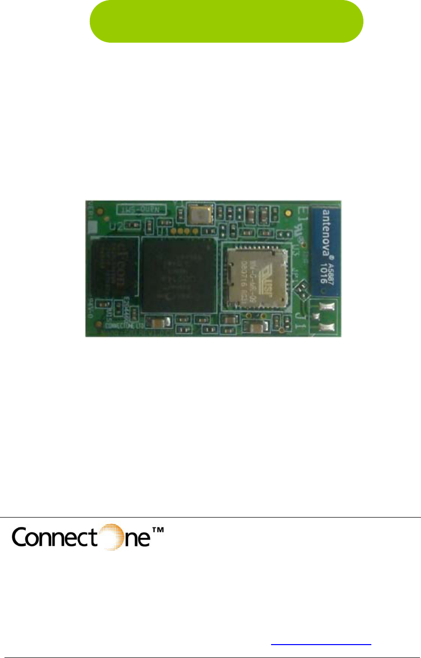
Nano WiReach™ SMT is a secure serial-to-
Wireless-LAN device server module that also
acts as a bridge to connect serial devices to
802.11b/g Wireless LANs. It includes the
iChip™ CO2144 IP Communication
Controller™ chip and Marvell 88W8686 WiFi
chipset. It is packaged in RoHS-compliant
ultra-slim form factor and uses an industry
standard pin-out. The Nano WiReach SMT
can also be interfaced to a 10/100BaseT
wired LAN and a USB cellular modem with
some external components and glue logic.
Nano WiReach SMT offers much more than
many other device servers on the market. It
acts as a security gap between the application
and the network; supports up to 10
simultaneous TCP/UDP sockets; two listening
sockets; a web server with two websites;
SMTP and POP3 clients; MIME attachments;
FTP and TELNET clients, and SerialNET™
mode for serial-to-IP bridging.
Nano WiReach SMT supports the SSL3/TLS1
protocol for secure sockets, HTTPS and
FTPS, WEP, WPA and WPA2 WiFi
encryption.
Nano WiReach SMT minimizes the need to
redesign the host device hardware. It features
a standard economical SMT footprint
providing for low-cost placement on a host
PCB with provisions for an on-board or
external antenna. Minimal or no software
configuration is needed for Nano WiReach
SMT to access the Wireless LAN.
Connect One’s high-level AT+i™ API
eliminates the need to add WiFi drivers,
security and networking protocols and tasks to
the host application. The AT+i SerialNET
operating mode offers a true plug-and-play
mode that eliminates any changes to the host
application.
Nano WiReach SMT firmware – the IP stack
and Internet configuration parameters – are
stored in an external flash memory. The
module is power-efficient: the core operates at
1.2V, while I/Os operate at 3.3V. Power Save
mode further reduces power consumption.
The II-EVB-365SMT evaluation board
provides an easy environment for testing the
Nano WiReach SMT prior to designing it into
your product.
1.2 Hardware
Description
Size: 37.0 x 20.0 x 2.5 mm
Core CPU: 32-bit RISC ARM7TDMI, low-
leakage, 0.13 micron, running at 48MHz
Operating Voltage: +3.3V+/-10%
Operating Humidity: 90% maximum (non-
condensing)
Operating Temperature Range:
-10° to 65°C (14° to 149°F)
Power Consumption:
Transmit – 250mA @16dbm
235mA @12dbm (typical)
Receive – 190mA (typical)
Power Save mode – 8mA
Optional : On-Board antenna
Optional: U.FL connector
Connection: 44 SMT pads
Host Interface: TTL Serial, SPI and USB 1.1
device.
A/D Input (see AT+I programmers manual)
Cellular Modem Interface: USB 1.1 Host
10/100BaseT LAN Interface: RMII (w/ext.
PHY)
RoHS-compliant; lead-free
1.3 Performance
Specifications
Host Data Rate: up to 3Mbps in serial mode
Serial Data Format (AT+i mode):
Asynchronous character; binary; 8 data bits;
no parity; 1 stop bit
SerialNET mode: Asynchronous character;
binary; 7 or 8 data bits; odd, even, or no
parity; 1 stop bit
Flow Control: Hardware (-RTS, -CTS) and
software flow control.
Nano WiReach SMTData Sheet 1-1

Connect One Introduction
Internet Protocols
Certifications:
ARP, ICMP, IP, UDP, TCP, DHCP, DNS,
NTP, SMTP, POP3, MIME, HTTP, FTP and
TELNET • Radio & EMC:
- USA
o FCC Modular Approval
o CFR Title 47 FCC Part 15, Subpart B
and C
- Canada
o Industry Canada Module Approval
o Industry Canada ICES-003, RSS-Gen,
RSS-210
- EU
o EN 300 328 (R&TTE Directive
1999/5/EC)
o EN 301 489 (EMC Directive
2004/108/EC)
• Safety:
o UL 60950
o CAN/CSA-C22.2 No. 60950
o EN 60950, Low Voltage Directive
(2006/95/EC)
Security Protocols
SSL3/TLS1, HTTPS, FTPS, RSA,
AES-128/256, 3DES, RC-4, SHA-1, MD-5,
WEP, WPA and WPA2
Protocols Accelerated in HW
AES, 3DES and SHA
Application Program Interface
Connect One’s AT+i protocol
SerialNET mode for transparent serial data-
to-Internet bridging
Wireless Specifications
Standards Supported: IEEE 802.11b, IEEE
802.11g
THIS DEVICE COMPLIES WITH PART
15 OF THE FCC RULES. OPERATION
IS SUBJECT TO THE FOLLOWING
TWO CONDITIONS: (1) THIS DEVICE
MAY NOT CAUSE HARMFUL
INTERFERENCE, AND (2) THIS
DEVICE MUST ACCEPT ANY
INTERFERENCE RECEIVED,
INCLUDING INTERFERENCE THAT
MAY CAUSE UNDESIRED
OPERATION.(*)
Frequency:
Europe – 2.412-2.472GHz
USA – 2.412-2.462GHz
Japan – 2.412–2.484GHz
Channels:
Europe – 13 channels
USA – 11 channels
Japan – 14 channels
Recommended Antenna (for U.FL option)
Installation Requirements
iW-ANT2-BL Antenna: 2.4GHz, 2.0dBi, 50Ω,
omni-directional, 1/4 wavelength dipole
configuration, VSWR≤2.0,
height - 82.5mm, weight – 6.3 grams
The Nano WiReach SMT must be installed
within a full-enclosure device that is safety
certified.
Warranty
One year
(*) NOTE: THE MANUFACTURER IS NOT RESPONSIBLE
FOR ANY RADIO OR TV INTERFERENCE
CAUSED BY UNAUTHORIZED
MODIFICATIONS TO THIS EQUIPMENT.
SUCH MODIFICATIONS COULD VOID THE
USER’S AUTHORITY TO OPERATE THE
EQUIPMENT
WiReach BK Data Sheet 1-2

Connect One Features
2 Features
2.1 Security
Acts as a security gap between the host application and the network
One secure SSL3/TLS1 socket
Provides WEP, WPA and WPA2 Wireless LAN security
Supports multiple Certificate Authorities and both client-side and server-side authentication
Secure FTP and HTTP clients (over SSL3)
Includes a true hardware random number generator
AES, 3DES and SHA accelerated in hardware
2.2 Protocols
Up to 10 simultaneous TCP/UDP sockets and two listening sockets
HTTP client
HTTP web server with two on-chip websites: configuration site and application site
FTP and TELNET clients
DHCP client and server
Sending and receiving textual email and binary email with MIME attachments
2.3 Additional Features
Non-volatile, on-chip operational parameter database
Supports infrastructure and ad-hoc Wireless LAN networks
SerialNET mode for serial-to-IP bridging (port server mode)
Local firmware update
Remote configuration and firmware update over the Internet
Retrieval of time data from a Network Time Server
Note: For a detailed description of all available features, see the
AT+i Programmer’s Manual.
Nano WiReach SMTData Sheet 2-1
Connect One Typical Applications
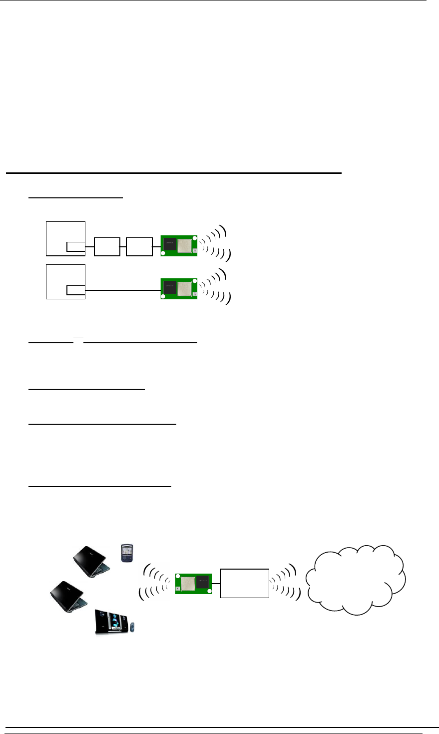
3 Typical Applications
Adding IP communications over WiFi to serial embedded devices.
Replacing a LAN cable with a WiFi connection.
Adding SSL security to M2M solutions.
Nano WiReach SMT supports several operational modes:
• LAN to WiFi Bridge - allowing transparent bridging of LAN over WiFi, using direct
RMII connection to existing MAC hardware or direct PHY-to-PHY connection.
EMAC Ethernet
PHY Ethernet
PHY
WiFi SMT
RMII
PHY-to-PHY
MAC-to-MAC
EMAC
WiFi SMT
Microcontroller
Microcontroller
• SerialNetTM Serial to WiFi Bridge - allowing transparent bridging of Serial over
WiFi, using a 3Mbps fast UART. This is a true plug-and-play mode that eliminates
any changes to the host application.
• PPP modem emulation – allowing existing (i.e. modem) designs currently using
PPP to connect transparently over WiFi.
• Full Internet Controller mode – allowing simple MCU to use the Nano WiReach
SMT’s rich protocol and application capabilities to perform complex Internet
operations such as E-mail, FTP, SSL, embedded Web server and others. It also acts
as a firewall, providing a security gap between the application and the network.
• LAN/WiFi Ù Cellular Router – allowing local systems, communicating over LAN
and/or WiFi, to gain WAN access to the Internet via a cellular modem. This mode
includes a DHCP server and NAT to support multiple local systems communicating
over a single cellular link.
Cellular
Modem
Internet
WiFi
Nano WiReach SMTData Sheet 3-1
Connect One Pin Descriptions
4 Connector Pin Description
The Nano WiReach SMT module includes the iChip CO2144 IP Communication Controller and the
Marvell 88W8686 802.11b/g WiFi chipset mounted on a socket form-factor module.
4.1 Pin Numbers
31
29
30
24
25
26
27
28
23
35 34 33 3240 39 38 37 36 4144 43 42
2
1
3
4
5
6
7
8
9
2221201914 15 16 17 18 10 11 12 13
Figure 3-
4-1: Pin-out for Nano WiReach SMT(Bottom view)
Nano WiReach SMTData Sheet 4-1

Connect One Pin Descriptions
Pin Functional Description
Pin Signal type Description
1 GND Power
2 HDM Analog USB Host negative
3 HDP Analog USB Host positive
4 nRESET Input Reset Module. Pull LOW for 100mSec to Reset
5 PIOC4 I/O General In/Output Port
6 MSEL Input Mode select. Used for inducing rescue mode
and forced local Firmware-update.
7 DATA_RDY Output Data ready. Signals incoming Internet data.
8 ETX_EN Output RMII Transmit Enable
9 REFCLK Input RMII Reference Clock 50Mhz
10 ETX0 Output RMII transmit Data 0
11 ETX1 Output RMII transmit Data 1
12 CRSDV Input RMII Carrier sense and Data Valid
13 ERX0 Input RMII Receive Data 0
14 ERX1 Input RMII Receive Data 1
15 ERXER Input RMII Receive Error
16 EMDC Output Management data Clock
17 EMDIO I/O Management data I/O
18 PIOC5 I/O General In/Output Port
19 VBUS Output VBUS for USB Host
20 Readiness Output iChip Ready status line. See AT+I
programmers manual.
21 PIOC3 I/O General In/Output Port
22 VDD Power 3.3V
23-31 GND Power
32 nRF_LED Output RF LED indicator
33 ACH Input Analog Input
34 SPI1_CLK Input SPI 1 clock for host (Max 12MHz)
35 nSPI1_CS Input SPI 1 chip select for host
36 SPI1_MISO Output SPI 1 slave out for host master in
37 SPI1_MOSI Input SPI 1 slave in for host master out
38 SPI1_INT Output SPI 1 have data on his buffer
39 TXD0 Output UART 0 transmit
40 RXD0 Input UART 0 receive
41 nCTS0 Input UART 0 clear to send
42 nRTS0 Output UART 0 request to send
43 DDM Analog USB device negative
44 DDP Analog USB device positive
Table 3-1: Connector Signal Description
WiReach BK Data Sheet 4-2
Connect One Interfaces
5 Interfaces
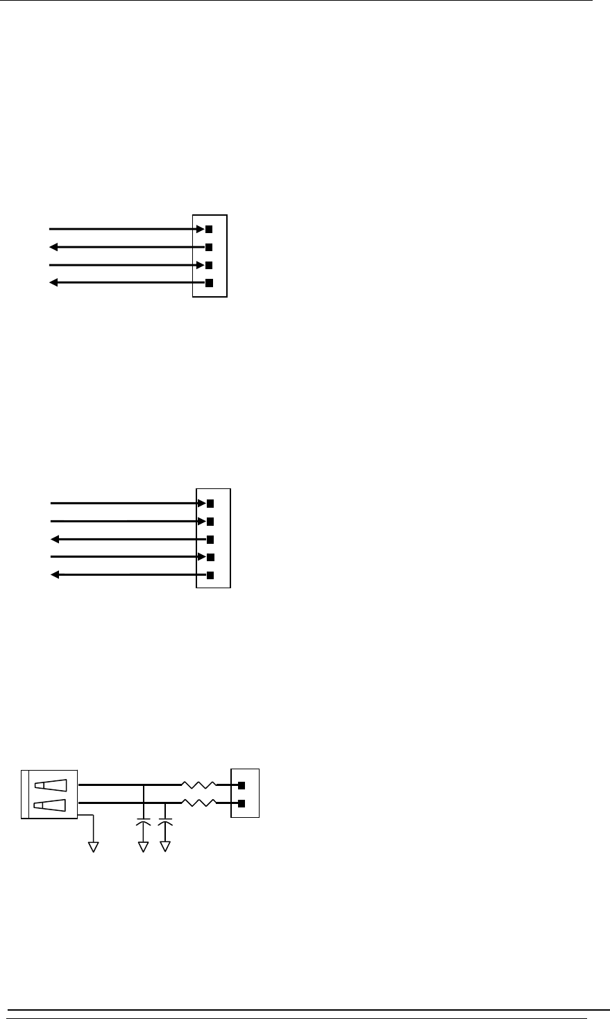
5.1 Serial Interface
5.2 SPI Interface
5.3 USB 1.1 Device Interface
nSPI1 CS
SPI1
_
CLK
SPI1_MISO
SPI1 MOSI
SPI1
_
INT
Nano WiReach SMT
p
ins
DDP
DDM
Nano WiReach SMT
p
ins
2
3
USB-B
27
27
15
p
F 15
p
F
4
RXD0
TXD0
nCTS0
nRTS0
Nano WiReach SMT pins
40
39
41
42
35
34
36
37
38
44
43
Nano WiReach SMTData Sheet 5-1
Connect One Interfaces
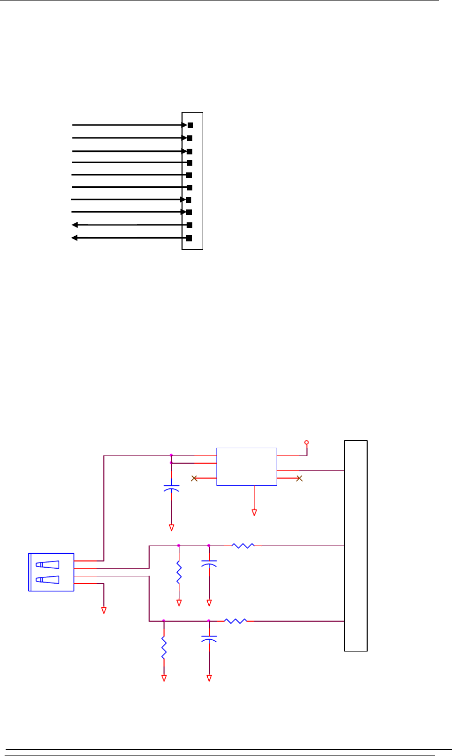
5.4 RMII Interface
ETX_EN
REFCLK
CRSDV
Nano WiReach SMT pins
10
11
14
13
16
17
15
8
9
12
EMDC
ERX0
ERX1
ETX0
ETX1
EMDIO
ERXER
5.5 USB 1.1 Host Interface
+
100UF//6.3V
HDM
GND
GND
GND
15K
27
HDP
27
47PF
GND
GND
47PF
15K
FOR USB MODEM
J2
1
2
3
4
GND
U5
AP2171
Vin 2
Vout
5
Vout
6
EN 3
VDD
VBUS
GND
1
FLG
4EP EP
GND
2
19
3
POWER SWITCH FOR USB
USB A
Nano WiReach SMT pins
WiReach BK Data Sheet 5-2

Connect One Electrical Specifications
6 Electrical Specifications
6.1 Absolute Maximum Ratings
Parameter Rating
Voltage at any pin with respect to ground -0.3V to +3.6V
Operating temperature -10°C to 65°C (14°F to 149°F)
Storage temperature -65°C to 125°C (-85°F to 257°F)
Table 4-1: Absolute Maximum Ratings
6.2 DC Operating Characteristics
Parameter Min Typical Max Units
VDD 3.0 3.3 3.6 Volts
High-level Input 2.0 VDD I/O+0.3 Volts
Low-level Input -0.3 0.8 Volts
High-level Output @2mA VDD I/O-0.4 Volts
High-level Output @0mA VDD I/O-0.2 Volts
Low-level Output @2mA 0.4 Volts
Low-level Output @0mA 0.2 Volts
Input leakage current 10 µA
Power supply current from VDD
(Transmit Mode)
260 280 mA
Power supply current from VDD
(Receive Mode)
190 210 mA
Power supply current from VDD
(Power Save Mode)
8* mA
Input Capacitance 5.3 pF
Radio Frequency Range
(subject to local regulation)
2.412 2.484 GHz
Table 4-2: DC Operating Characteristics
(*) Note: Power supply current as measured in firmware version i2128d722B05.
Nano WiReach SMTData Sheet 6-1
Connect One Electrical Specifications
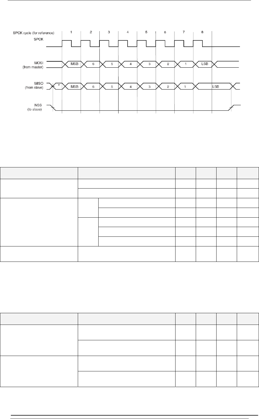
6.3 AC Operating Characteristics
Figure
6-1: SPI Interface Waveforms
6.4 Tx Specifications
Item Condition Min Typ Max Unit
11b 15 dBm Transmit Power Levels
11g 15 dBm
Fc+/-11MHz 40 dBc 11b
Fc+/-22MHz 60 dBc
Fc+/-11MHz 30 dBc
Fc+/-20MHz 40 dBc
Transmit Spectrum Mask
11g
Fc+/-30MHz 50 dBc
Transmit Center Frequency
Tolerance
Temperature=25°C ±10 ppm
Table 4-3: Tx Specifications
6.5 Rx Specifications
Item Condition Min Typ Max Unit
802.11b Data Rate=11Mbps,
PER<8%
-88 dBm Receiver Minimum Input
Level Sensitivity
802.11g Data Rate=54Mbps,
PER<10%
-74 dBm
802.11b Data Rate=11Mbps,
PER<8%
48 dBc Adjacent Channel Rejection
Desired channel is 3dB above
sensitivity 802.11g Data Rate=54Mbps,
PER<10%
15 dBc
Table 4-4: Rx Specifications
PER(%)=(Number of all packets – Number of received packets)/(Number of all packetsX100)
WiReach BK Data Sheet 6-2
Connect One Electrical Specifications
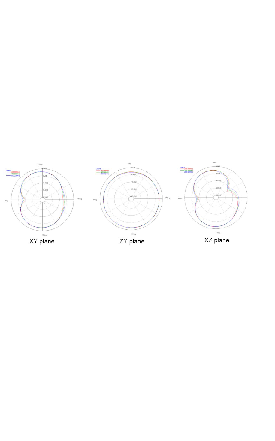
7 On-Board Antenna
Designed for 2.4Ghz operation
Peak Gain: 2.1 dBi
Average efficiency: 75%
Max return loss: -11dBi
Max VSWR: 1.8:1
Antenna Patterns:
WiReach BK Data Sheet 7-3
Connect One Mechanical Dimensions
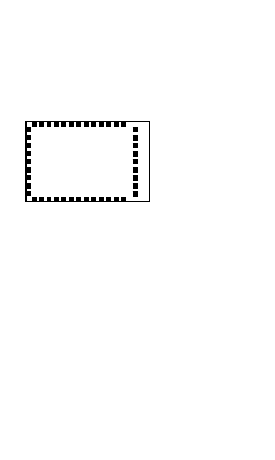
8 Mechanical Dimensions
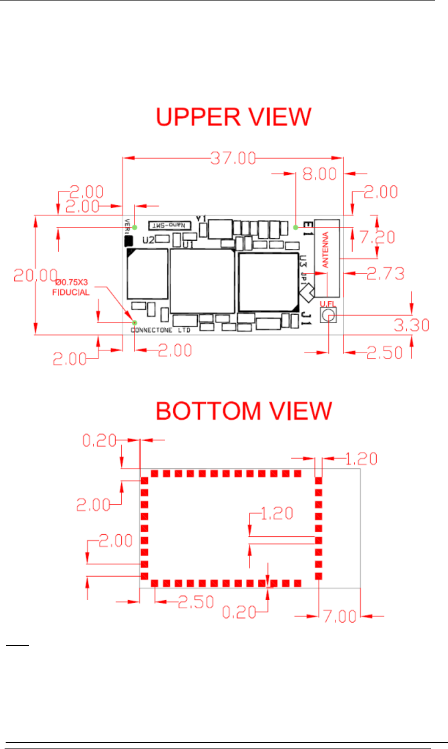
ote:
N All measures are in millimeters +/- 0.2 mm
Figure 5- 8-1: Mechanical Dimensions
Nano WiReach SMTData Sheet 8-1
Connect One Mechanical Dimensions
WiReach BK Data Sheet 8-2
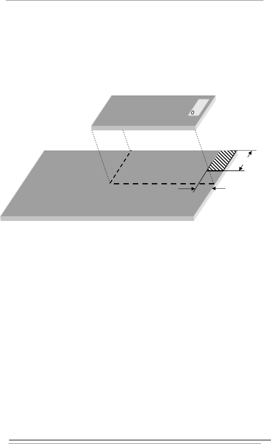
8.1 Antenna Clearance Recommendation
The striped area below should be clear of metal, ground planes and wiring:
Figu
re 5- 8-2: Antenna Clearance
E1
NanoWiReachSMT
Host-PCB
18.01
8.24
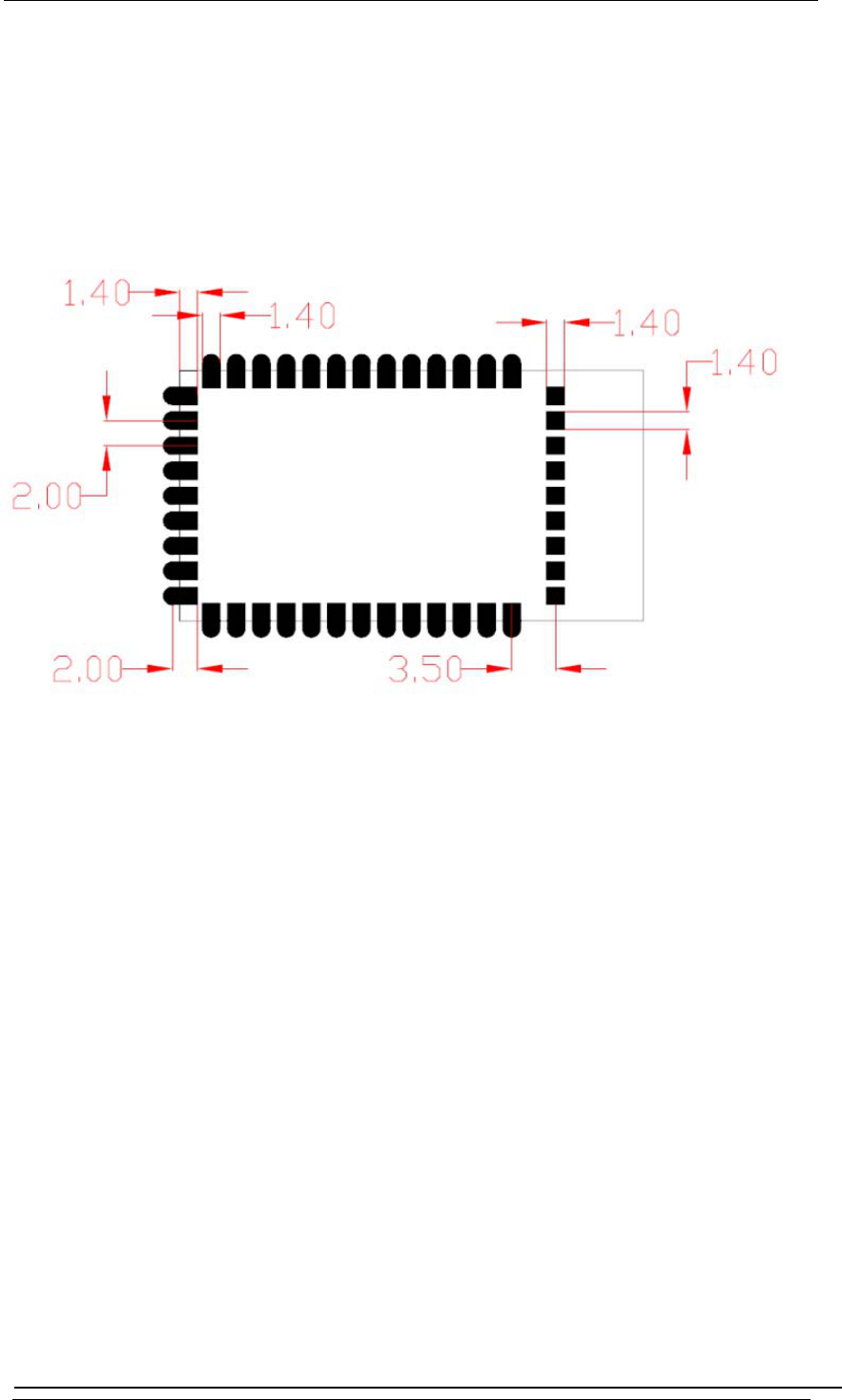
Connect One Recommended Footprint
9 Recommended PCB Footprint
Figure 5- 9-1: Recommended PCB Footprint
Nano WiReach SMTData Sheet 9-1

Connect One Evaluation Board
10 Evaluation Board
The II-EVB-365smt evaluation board enables you to evaluate the Nano WiReach SMT without
hanging anything in your current development environment. Using a simple Windows-based
pplication on a PC, you can issue AT+i commands to the iChip CO2144 and get responses.
Note: The evaluation board supports serial host data rates of up to
c
a
1Mbps.
AT+i commands are used to configure parameter values into iChip’s flash memory and activate
ernet tasks such as email send, sockets, FTP sessions, configuration, and more.
l description of AT+i commands can be found in the AT+i Programmer’s Manual on Connect
ne’s website at: http://www.connectone.com/support.asp?did=35
Int
A ful
O
To help you evaluate the Nano WiReach SMT, Connect One supplies the iChip Config Utility. This
a Windows-based application that contains intuitive dialog boxes to fully configure iChip CO2144.
esn’t require any knowledge of AT+i commands. It also contains local firmware update
nctionality. The iChip Config Utility allows you to perform specific Internet communication tasks
uch as sending and receiving emails, activating iChip’s websites, entering SerialNET mode, and
ore. The latest iChip Config Utility version and user manual can be found on Connect One’s
ebsite under the Support section.
n board connectors allow a choice of Host interfaces:
• RS232 COM port
• SPI
• USB Device
is
It do
fu
s
m
w
O
Nano WiReach SMTData Sheet 10-1

Connect One Ordering Information
11 Ordering Information
Ordering Information
Part Number Description
iW- SM214 4SMT-EX Nano WiReach SMT module, External Antenna
iW- SM2144SMT-OB Nano WiReach SMT module, On-board Antenna
II-EVB-365SMT Evaluation board for Nano WiReach SMT module, On-board Antenna
iW-CAB-150 Miniature coaxial w/ pigtail cable. UFL-SMA connectors. 150mm length.
iW-ANT2-BL 2.4GHz WiFi antenna, 2.0dBi, 50Ω, omni-directional,
1/4 wavelength dipole configuration
Nano WiReach SMTData Sheet 11-1

Connect One Protocol Compliance
12 Internet Protocol Compliance
ano WiReach SMT complies with the Internet standards listed in the following table.
datagram protocol (UDP)
N
RFC 768 User
RFC 791 Internet protocol (IP)
RFC 792 ICMP – Internet control message protocol
RFC 793 Transmission control protocol (TCP)
RFC 821 Simple mail transfer protocol (SMTP)
RFC 822 Standard for the format of ARPA Internet text messages
RFC 826 Ethernet address resolution protocol (ARP)
RFC 959 File transfer protocol (FTP)
54 TELNET protocol specification
RFC 8
57 Telnet ECHO option
RFC 8
58 Telnet suppress go-ahead option
RFC 8
034 Domain names (DNS) - concepts and facilities
RFC 1
035 Domain names (DNS) - implementation and specification
RFC 1
073 Telnet window size option
RFC 1
091 Telnet terminal type option
RFC 1
321 MD5 message digest algorithm
RFC 1
939 Post office protocol - version 3 (POP3)
RFC 1
957 Some observations on the implementations of the post office protocol (POP3)
RFC 1
030 Simple network time protocol (SNTP)
RFC 2
RFC 2045 Multipurpose Internet mail extensions (MIME) part one: internet message body format
RFC 2046 MIME part two: media types
RFC 2047 MIME part three: message header extensions for non-ASCII text
RFC 2048 MIME part four: registration procedures
RFC 2049 MIME part five: conformance criteria and examples
RFC 2068 Hypertext transfer protocol HTTP/1.1
RFC 2131 Dynamic host configuration protocol (DHCP)
RFC 2132 DHCP options (only relevant parts)
RFC 2228 FTP security extensions
RFC 2246 The TLS protocol version 1.0
Table
12-1: Internet Protocol Compliance
Nano WiReach SMTData Sheet 12-1