Connect One SMG2N2 Nano Socket WiFi 2nd Generation 802.11b/g/n User Manual
Connect One Ltd. Nano Socket WiFi 2nd Generation 802.11b/g/n
User manual
Connect One Ltd. 20 Atir Yeda Street, Kfar Saba 44643, Israel | Phone: +972-9-766-0456 | Fax: +972-9-766-0461 Email: sales@connectone.com | www.connectone.com
Datasheet
Nano Socket iWiFi G2 N2
Version 1.1

Nano Socket iWiFi G2 N2 –Datasheet
2
Information provided by Connect One Ltd. is believed to be accurate and reliable. However, Connect One Ltd. assumes no
responsibility for its use, nor any infringement of patents or other rights of third parties, which may result from its use. No license
is granted by implication or otherwise under any patent rights of Connect One Ltd. other than for circuitry embodied in
Connect One’s products. Connect One Ltd. reserves the right to change circuitry at any time without notice. This document is
subject to change without notice.
The software described in this document is furnished under a license agreement and may be used or copied only in accordance
with the terms of such a license agreement. It is forbidden by law to copy the software on any medium except as specifically
allowed in the license agreement. No part of this document may be reproduced or transmitted in any form or by any means,
electronic or mechanical, including but not limited to photocopying, recording, transmitting via fax and/or modem devices,
scanning, and/or information storage and retrieval systems for any purpose without the express written consent of Connect One.
WARNING: THE Nano Socket iWiFi G2 N2 IS AN RF MODULE INTENDED FOR EMBEDDING IN A HOST DEVICE. LOCAL RELEVANT RF
REGULATIONS SUCH AS ALLOWED FREQUENCIES AND USAGE IN COMMERCIAL FLIGHTS MUST BE OBSERVED. SAFETY
INSTRUCTIONS MUST BE INCLUDED IN THE MANUALS OF THE HOST DEVICE. CONNECT ONE ASSUMES NO LIABILITY FOR
CUSTOMER FAILURE TO COMPLY WITH THESE PRECAUTIONS.

Nano Socket iWiFi G2 N2 –Datasheet
3
iChip, Nano Socket iWiFi G2 N2, IP Communication Controller, SerialNET, AT+i and Connect One are
trademarks of Connect One Ltd. Copyright 2014 Connect One Ltd. All rights reserved.
Industry Canada Warning Statements:
This device complies with Industry Canada’s licence-exempt RSSs. Operation is subject to the following two conditions:
(1) This device may not cause interference; and (2) This device must accept any interference, including interference that
may cause undesired operation of the device.
Cet appareil est conforme aux CNR exemptes de licence d'Industrie Canada . Son fonctionnement est soumis aux deux
conditions suivantes : ( 1 ) Ce dispositif ne peut causer d'interférences ; et ( 2 ) Ce dispositif doit accepter toute
interférence , y compris les interférences qui peuvent causer un mauvais fonctionnement de l'appareil
IC Radiation Exposure Statement
The modular can be installed or integrated in mobile or fix devices only. This modular cannot be installed in any portable
device, for example, USB dongle like transmitters is forbidden.
This modular complies with IC RF radiation exposure limits set forth for an uncontrolled environment. This transmitter must
not be co-located or operating in conjunction with any other antenna or transmitter. This modular must be installed and
operated with a minimum distance of 20 cm between the radiator and user body. Cette modulaire doit être installé et utilisé
à une distance minimum de 20 cm entre le radiateur et le corps de l'utilisateur.
If the IC number is not visible when the module is installed inside another device, then the outside of the device into which
the module is installed must also display a label referring to the enclosed module. This exterior label can use wording such
as the following: “Contains IC: 8516A-SMG2N2”
when the module is installed inside another device, the user manual of this device must contain below warning statements;
1. This device complies with Industry Canada’s licence-exempt RSSs. Operation is subject to the following two conditions:
(1) This device may not cause interference; and
(2) This device must accept any interference, including interference that may cause undesired operation of the device.
2. Cet appareil est conforme aux CNR exemptes de licence d'Industrie Canada . Son fonctionnement est soumis aux deux
conditions suivantes :
( 1 ) Ce dispositif ne peut causer d'interférences ; et
( 2 ) Ce dispositif doit accepter toute interférence , y compris les interférences qui peuvent causer un mauvais
fonctionnement de l'appareil.
The devices must be installed and used in strict accordance with the manufacturer's instructions as described in the user
documentation that comes with the product
FCC Warning Statements:
This device complies with part 15 of the FCC Rules. Operation is subject to the following two conditions: (1) This device
may not cause harmful interference, and (2) this device must accept any interference received, including interference that
may cause undesired operation.
Changes or modifications not expressly approved by the party responsible for compliance could void the user's authority
to operate the equipment.
FCC Radiation Exposure Statement
The modular can be installed or integrated in mobile or fix devices only. This modular cannot be installed in any portable
device, for example, USB dongle like transmitters is forbidden.
This modular complies with FCC RF radiation exposure limits set forth for an uncontrolled environment. This transmitter
must not be co-located or operating in conjunction with any other antenna or transmitter. This modular must be installed
and operated with a minimum distance of 20 cm between the radiator and user body.
If the FCC identification number is not visible when the module is installed inside another device, then the outside of the
device into which the module is installed must also display a label referring to the enclosed module. This exterior label can
use wording such as the following: “Contains Transmitter Module FCC ID: XM5-SMG2N2 Or Contains
FCC ID: XM5-SMG2N2”
when the module is installed inside another device, the user manual of this device must contain below warning statements;
1. This device complies with Part 15 of the FCC Rules. Operation is subject to the following two conditions:
(1) This device may not cause harmful interference.
(2) This device must accept any interference received, including interference that may cause undesired operation.
2. Changes or modifications not expressly approved by the party responsible for compliance could void the user's authority
to operate the equipment.
The devices must be installed and used in strict accordance with the manufacturer's instructions as described in the user
documentation that comes with the product

Nano Socket iWiFi G2 N2 –Datasheet
4
Table of Contents
Revision History .................................................................................................................................................... 6
1. Introduction ................................................................................................................................................... 7
1) General Description .................................................................................................................................. 7
2) Hardware Description ............................................................................................................................... 9
3) Performance Specifications ...................................................................................................................... 9
4) Internet Protocols ..................................................................................................................................... 9
5) Security Protocols ..................................................................................................................................... 9
6) Application Program Interface (API) ......................................................................................................... 9
7) Wireless Specifications ........................................................................................................................... 10
8) Certification ............................................................................................................................................ 10
9) Installation Requirements ...................................................................................................................... 10
2. Features ....................................................................................................................................................... 11
1) Security ................................................................................................................................................... 11
2) Protocols ................................................................................................................................................. 11
3) Additional Features ................................................................................................................................. 11
3. Typical Applications ..................................................................................................................................... 12
4. AT+i Command Set ...................................................................................................................................... 13
5. Layout, Mechanical Dimensions and Pin Description ................................................................................. 14
1) Layout and Mechanical Dimensions ....................................................................................................... 14
2) Pin Functional Description ...................................................................................................................... 15
6. Interfaces ..................................................................................................................................................... 16
1) Serial Interface ........................................................................................................................................ 16
2) SPI Interface ............................................................................................................................................ 16
3) USB 2.0 Device Interface ........................................................................................................................ 17
4) RMII Interface ......................................................................................................................................... 17
7. Electrical Specifications ............................................................................................................................... 18
1) Absolute Maximum Ratings .................................................................................................................... 18

Nano Socket iWiFi G2 N2 –Datasheet
5
2) DC Operating Characteristics .................................................................................................................. 18
3) AC Operating Characteristics .................................................................................................................. 19
4) Transmit Specification ............................................................................................................................ 19
5) Receive Specifications............................................................................................................................. 19
8. On Board Antenna ....................................................................................................................................... 20
1) Specifications .......................................................................................................................................... 20
9. Evaluation Board ......................................................................................................................................... 21
10. Ordering Information .............................................................................................................................. 21
Appendix A - Internet Protocol Compliance ....................................................................................................... 22
Appendix B – AT+I Configuration Examples ....................................................................................................... 23
Automatically connect to a specific Access Point:.............................................................................. 23
Create an Access Point to allow connection from mobile devices: ................................................... 23
LAN – WiFi switch mode - merges Ethernet station(s) with WiFi client(s) into one logical subnet ... 23

Nano Socket iWiFi G2 N2 –Datasheet
6
Revision History
Version
Date
Description
1.0
June 1st 2014
Initial preliminary version
1.1
July 14th 2014
Adding Security Features

Nano Socket iWiFi G2 N2 –Datasheet
7
1. Introduction
1) General Description
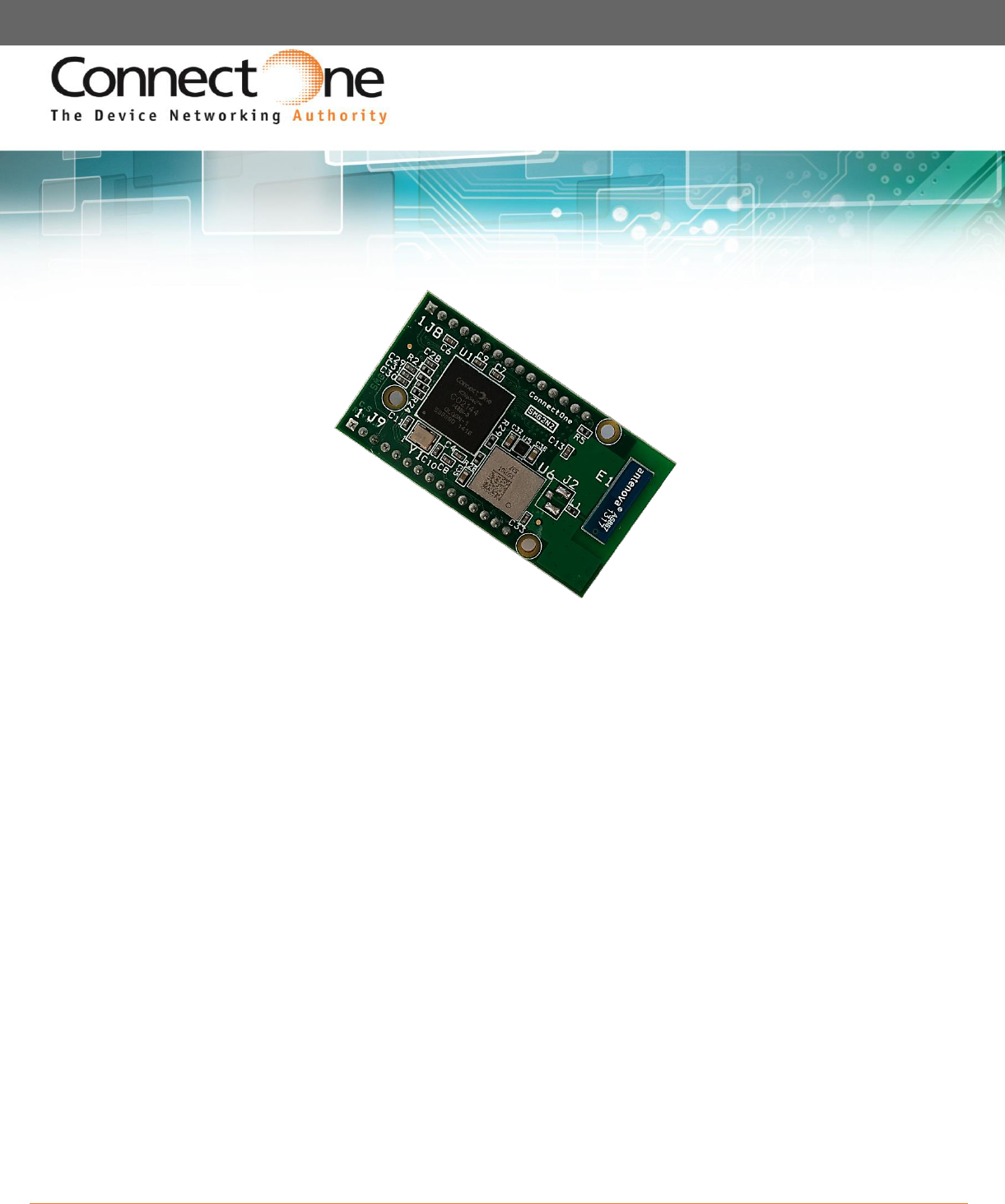
Nano Socket iWiFi™ G2 N2 is a secure serial-to-Wireless-LAN device module that can perform as a
WLAN client or Access Point to connect serial devices to 802.11b/g/n Wireless LANs. It includes the
iChip™ CO2144 IP Communication Controller™ chip and Broadcom BCM43362 WiFi chipset. It is
packaged 45.21X24.88 RoHS-compliant module with two 1X15 PIN headers and onboard antenna.
Nano Socket iWiFi G2 N2 offers and supports large variety of features which among them:
Ten simultaneous TCP/UDP sockets
Two listening sockets
Webserver with two websites
SMTP and POP3 clients
DHCP client/server
POP3 SMTP client with MIME attachment
FTP client
TELNET client
SerialNET™ mode for serial to IP bridging
Gateway between a local network on it’s LAN/WLAN interfaces and a WAN on any of
it’s other interfaces
Switch between it’s WLAN interface and the Ethernet interface when acting as a WLAN
access point
An Ethernet to WiFi bridge to connect an ETH client to a WiFi network (cable
replacement)
Security gap between the application and the network
Nano Socket iWiFi G2 N2 supports the SSL3/TLS1 protocol for secure sockets, HTTPS, FTPS and
secure web server. On the WLAN interface it supports: WEP, WPA and WPA2 WiFi encryption.
Nano Socket iWiFi G2 N2 minimizes the need to redesign the host device hardware. It easily inserts
into a two 1X15 female header connector on the host PCB and requires no external antenna
connections. Minimal or no software configuration is needed for Nano Socket iWiFi G2 N2 to access
the Wireless LAN.
Connect One’s high-level AT+i™ API eliminates the need to add WiFi drivers, security and
networking protocols and tasks to the host application. The AT+i SerialNET operating mode offers a
true plug-and-play mode that eliminates any changes to the host application.

Nano Socket iWiFi G2 N2 –Datasheet
8
Nano Socket iWiFi G2 N2 firmware – the IP stack and Internet configuration parameters – are stored
in an external FLASH memory.
The II-EVB-363-G2-N2 evaluation board provides an easy environment for testing the Nano Socket
iWiFi G2 N2 prior to designing it into your product.

Nano Socket iWiFi G2 N2 –Datasheet
9
2) Hardware Description
Size: 45.21 x 24.88 x 9.00 mm
Core CPU: 32-bit RISC ARM7TDMI,
Low-leakage, 0.13 micron, at 48MHz
Operating Voltage: +3.3V+/-10%
Operating Humidity: 90% maximum (non-condensing)
Operating Temperature Range: -30°C to +85°C
-22°F to 185°F
Power Consumption (max): Transmit – 350mA@11Mbps, 310mA@54Mbps,
310mA@72Mbps
Receive – 130mA
Antenna: Onboard 2DBi PACB type
Connection: Two 1X15 pin header
Host Interface: Serial, SPI, USB Device
A/D Input
10/100 Base T LAN Interface: RMII (w/ext. PHY)
3) Performance Specifications
Host Data Rate: Up to 3Mbps in serial mode
Serial Data Format (AT+i mode): Asynchronous character; binary; 8 data bits; no parity; 1 stop bit
SerialNET mode: Asynchronous character; binary; 7 or 8 data bits; odd, even, or
no parity; 1 stop bit
Flow Control: Hardware (-RTS, -CTS) and software flow control.
4) Internet Protocols
ARP, ICMP, IP, UDP, TCP, DHCP, DNS, NTP, SMTP, POP3, MIME, HTTP, FTP and TELNET
5) Security Protocols
SSL3/TLS1, HTTPS, FTPS, RSA, AES-128/256, 3DES, RC-4, SHA-1, MD-5, WEP, WPA and WPA2
Accelerated in HW: AES, 3DEC and SHA
6) Application Program Interface (API)
Connect One’s AT+i protocol

Nano Socket iWiFi G2 N2 –Datasheet
10
7) Wireless Specifications
Standards supported:
Frequency:
IEEE 802.11b/g/n
USA: 2.412-2.462GHz
Canada: 2.412–2.462GHz
Channels: USA: 11 channels
Canada: 11 channels
8) Certification
Radio & EMC:
USA
FCC Limited Modular Approval
CFR Title 47 FCC Part 15, Subpart B and C
Canada
Industry Canada Limited Module Approval
Industry Canada ICES-003, RSS-Gen, RSS-210
EU
EN 300 328
EN 301 489
Safety:
UL 60950
CAN/CSA-C22.2 No. 60950
EN 60950, Low Voltage Directive
9) Installation Requirements
The Nano Socket iWiFi N2 G2 must be installed within a full-enclosure device that is safety certified.

Nano Socket iWiFi G2 N2 –Datasheet
11
2. Features
1) Security
Acts as a security gap between the host application and the network
One secure SSL3/TLS1 socket
Provides WEP, WPA and WPA2 Wireless LAN security
Supports multiple Certificate Authorities and both client-side and server-side authentication
Secure FTP and HTTP clients (over SSL3)
Secure Web Server
Includes a true hardware random number generator
AES, 3DES and SHA accelerated in hardware
2) Protocols
Up to 10 simultaneous TCP/UDP sockets and two listening sockets
HTTP client
HTTP web server with two on-chip websites: configuration site and application site
FTP and TELNET clients
DHCP client and server
POP3 or SMTP client allows sending and receiving textual and binary email with MIME attachments
3) Additional Features
Supports infrastructure Wireless LAN networks
SerialNET mode for serial-to-IP bridging (port server mode)
Local firmware update
Remote configuration and firmware update over the Internet
Note: For a detailed description of all available features, see the AT+i Programmer’s Manual.
Nano Socket iWiFi G2 N2 –Datasheet
12
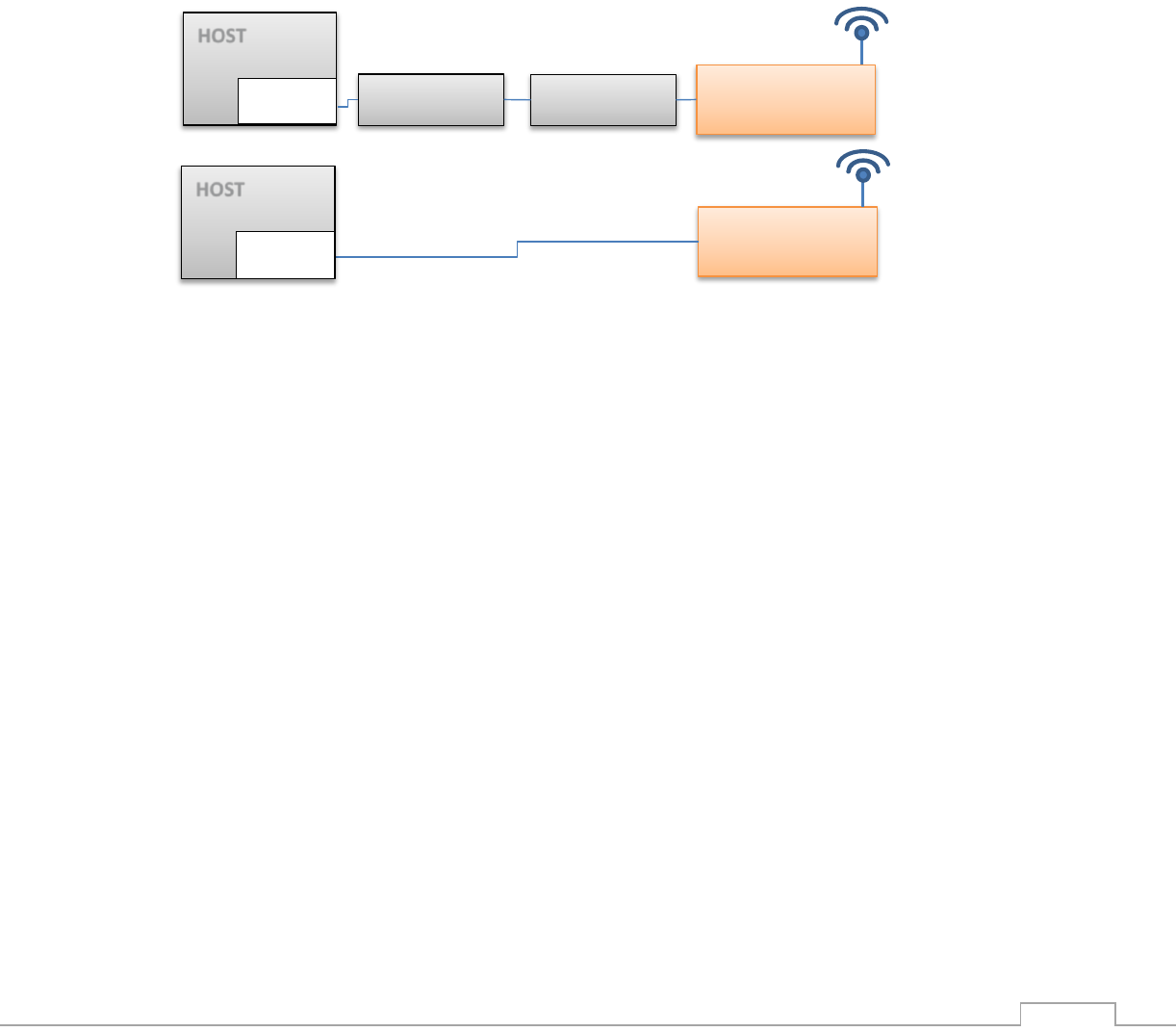
3. Typical Applications
Adding IP communications over WiFi to serial embedded devices.
Replacing a LAN cable with a WiFi connection.
Adding SSL security to M2M solutions.
LAN to WiFi Bridge - allowing transparent bridging of LAN client over WiFi (Cable replacement),
using direct RMII connection to existing MAC hardware or direct PHY-to-PHY connection.
SerialNetTM Serial to WiFi Bridge - allowing transparent bridging of Serial over WiFi, using a 3Mbps
fast UART. This is a true plug-and-play mode that eliminates any changes to the host application.
PPP modem emulation – allowing existing (i.e. modem) designs currently using PPP to connect
transparently over WiFi.
Full Internet Controller mode – allowing simple MCU to use the Nano Socket iWiFi G2 N2’s rich
protocol and application capabilities to perform complex Internet operations such as E-mail, FTP,
SSL, embedded Web server and others. It also acts as a firewall, providing a security gap between
the application and the network.
HOST
EMAC
Ethernet
Ethernet
Nano Socket
iWiFi G2 N2
Nano Socket
iWiFi G2 N2
MAC to MAC
RMII
PHY to PHY
HOST
EMAC

Nano Socket iWiFi G2 N2 –Datasheet
13
LAN WiFi / WiFi LAN Gateway – allowing local systems, communicating over LAN and/or
WiFi, to gain WAN access to the Internet. The WAN can be implemented using WiFi / LAN. A user
configurable parameter allows the WAN to be configured to one of the iChip network interfaces.
This mode includes a DHCP server and NAT to support multiple local systems communicating over a
single link.
4. AT+i Command Set
The iW-SMG2N2 is configured and controlled using proprietary AT+i protocol. You can create a
quick configuration using our AT+i Configuration Wizard located in Connect One’s website
http://www.connectone.com. In addition, the AT+i Programmer's Manual includes commends
description and format of the entire AT+i command set.
Please refer to Appendix B for examples of module configuration using AT+i command set.
HOST Computer
IW-SMG2N2
Access point
WAN
WiFi 802.11 b/g/n
Nano Socket iWiFi G2 N2 –Datasheet
14
5. Layout, Mechanical Dimensions and Pin Description
1) Layout and Mechanical Dimensions
Side View
Bottom View
Top View
Headers: Two 1X15pin Male 2mm pitch
Mate with: Two 1X15 Female 2mm Pitch
Samtec Part Number: #SQT-115-01-F-S
Or compatible
1.60
2.00
1.20
0.50 SQ
3.90
45.21
34.00
2.00
2.00
Ø4.00
Ø2.20
24.88
16.00
5.00
J9
J8
1
15
1
15
2.00
2.00
2.00
2.00
2.00
All measurements are in mm. Tolerance:
Length/Width +/-0.15mm, PCB thickness +/-
10%, Plated bores: +/-0.075mm, Non-Plated
bores: 0.05mm, Bore positions: +/- 0.1mm

Nano Socket iWiFi G2 N2 –Datasheet
15
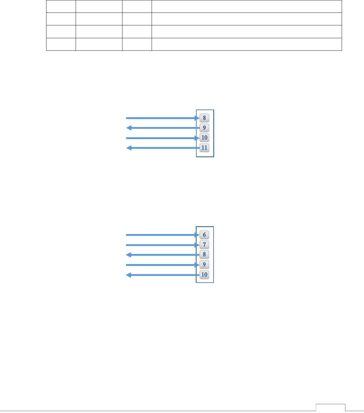
2) Pin Functional Description
J8 Pin Assignment
Pin
Signal
Type
Description
1
ERX0
Input
RMII Receive Data 0
2
ERX1
Input
RMII Receive Data 1
3
EMDC
Output
Management Data Clock
4
ERXER
Input
RMII Receive Error
5
RMII REFCLK
Input
RMII 50Mhz Reference Clock
6
GND
Power
Ground
7
VDD
Power
VDD
8
RXD0
Input
UART 0 Receive
9
TXD0
Output
UART 0 Transmit
10
nCTS0
Input
UART 0 Clear To Send
11
nRTS0
Output
UART 0 Request To Send
12
DATA RDY
Output
Data Ready - High when data rec. from Internet is buffered
13
MSEL
Input
Mode Select – Rescue and force F/W update
14
nReset
Input
Reset Module – Pull LOW for 100mSec to Reset
15
nRF LED
Output
RF LED Indicator
J9 Pin Assignment
1
ETX0
Output
RMII Transmit Data 0
2
ETX1
Output
RMII Transmit data 1
3
EMDIO
In/out
Management data I/O
4
CRSDV
Input
RMII Carrier Sense and Data Valid
5
ETXEN
Output
RMII Transmit Enable
6
nSPI CS
Input
SPI1 Host Chip Select for host
7
SPI1 CLK
Input
SPI1 Clock for host (Max 12MHz)
8
SPI1 MISO
Output
SPI1 Slave Out for host master in
9
SPI1 MOSI
Input
SPI1 Slave in for host master out
10
SPI1 INT
Output
SPI1 have data on buffer
11
Readiness
Output
High when iChip Ready for commands
Nano Socket iWiFi G2 N2 –Datasheet
16
12
DDM
Analog
USB Device Negative
13
DDP
Analog
USB Device Positive
14
N.C.
Not Connected
15
GND
Power
Ground
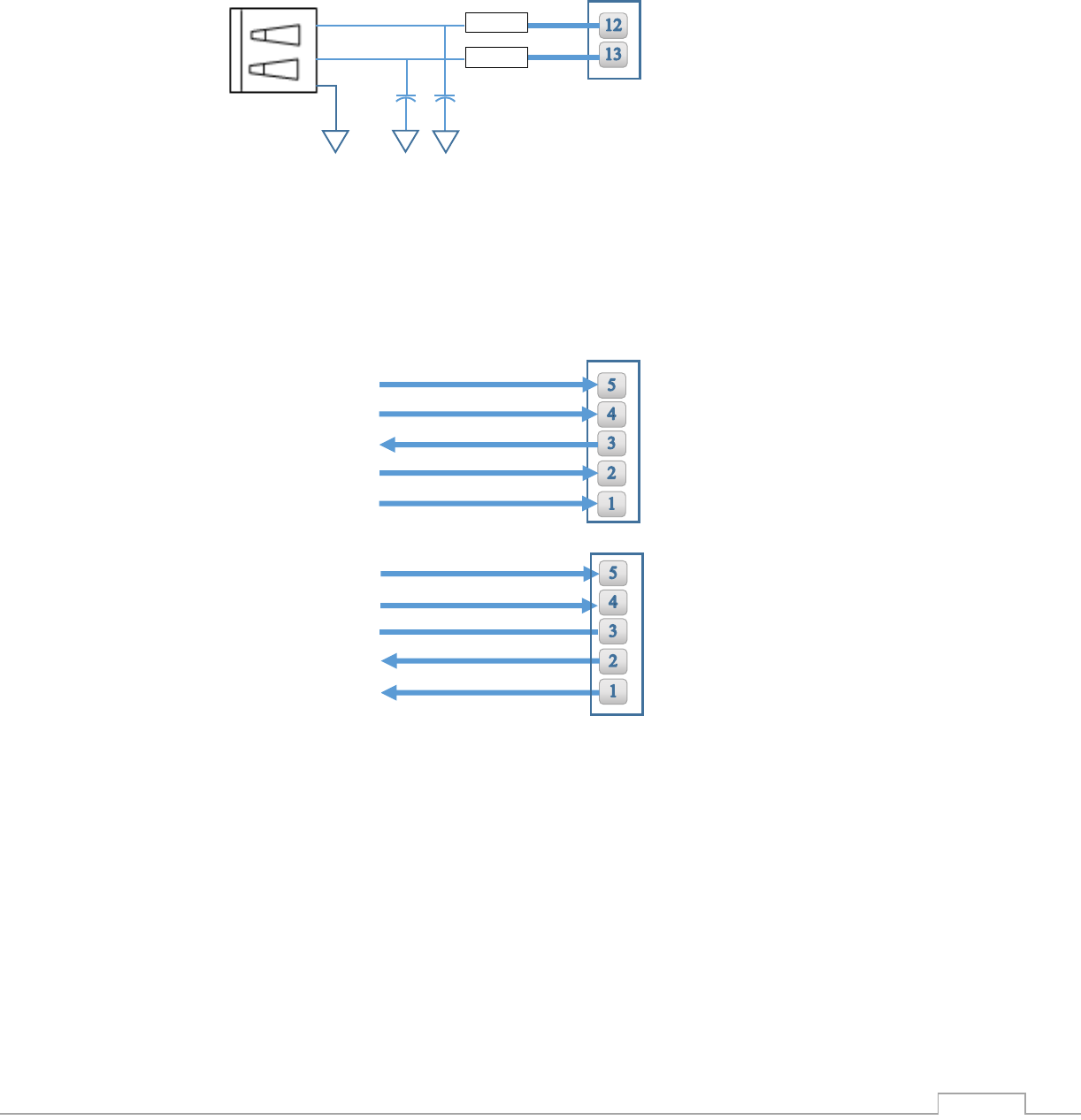
6. Interfaces
1) Serial Interface
2) SPI Interface
RXD0
TXD0
nCTS0
nRTS0
Nano G2 N2 J8
Note: If UART is not used, leave TXD0 and RXD0 N.C and short nCST0 to nRTS0
nSPI1 CS
SPI1 CLK
SPI1 MISO
SPI1 MOSI
Nano G2 N2 J9
SPI1 INT
Note: If SPI is not used leave all signals N.C
Nano Socket iWiFi G2 N2 –Datasheet
17
3) USB 2.0 Device Interface
4) RMII Interface
Nano G2 N2 J9
USB B
27Ω
27Ω
15pF
15pF
3
2
4
Note: If USB is not used leave all signals N.C
ETX EN
REF CLK
Nano G2 N2 J8
CRSDV
ERXER
EMDIO
EMDC
ERX0
ERX1
ETX0
ETX1
Nano G2 N2 J9
Note: If RMII is not used leave all signals N.C
Nano Socket iWiFi G2 N2 –Datasheet
18
7. Electrical Specifications
1) Absolute Maximum Ratings
Parameter
Rating
Voltage at any pin with respect to ground
-0.3V to +3.6V
Operating Temperature
-30⁰C to +85⁰C -22⁰F to +185⁰F
Storage Temperature
-40⁰C to +85⁰C -40⁰F to +185⁰F
2) DC Operating Characteristics
Parameter
Min
Typical
Max
Units
VDD
3.0
3.3
3.6
Volts
High Level Input
2.0
VDD I/O +0.3
Volts
Low Level Input
-0.3
0.8
Volts
High Level Output @2mA
VDD I/O -0.4
Volts
High Level Output @0mA
VDD I/O-0.2
Volts
Low Level Output @2mA
0.4
Volts
Low Level Output @0mA
0.2
Volts
Input Leakage Current
10
µA
Power Supply Current from VDD (Tx. Mode)
350
mA
Power Supply Current from VDD (Rcv. Mode)
130
mA
Power Supply Current from VDD (Power Save
Mode)
TBD
mA
Input Capacitance
5.3
pF
Radio Frequency Range
2.412
2.462
GHz
Nano Socket iWiFi G2 N2 –Datasheet
19
3) AC Operating Characteristics
4) Transmit Specification
Transmit Error vector
Magnitude
802.11b 11Mbps -13 -11 dB
1Mbps -13 -11 dB
802.11g 54Mbps -30 -25 dB
6Mbps -30 -22 dB
802.11n HT20M@MCS0 -30 -22 dB
HT20M@MCS0 -30 -28 dB
5) Receive Specifications
Item
Condition
Min
Typ
Max
Unit
Receiver Minimum
Input Level Sensitivity
802.11b Data Rate = 11Mbps PER < 8%
-87
-83
dBm
802.11b Data Rate = 1Mbps PER < 8%
-94
-89
dBm
802.11g Data Rate = 54Mbps PER <10%
-73
-68
dBm
802.11g Data Rate = 6Mbps PER <10%
-86
-81
dBm
802.11n MCS0 PER <10%
-86
-81
dBm
802.11n MCS7 PER <10%
-70
-65
dBm
Nano Socket iWiFi G2 N2 –Datasheet
20
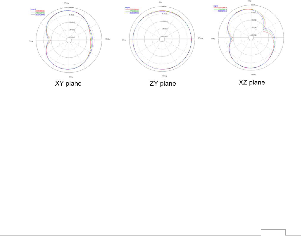
8. On Board Antenna
1) Specifications
Designed for: 2.4Ghz operation
Peak Gain: 2.1DBi
Avg. Efficiency: 75%
Max Return Loss: -11DBi
Max VSWR: 1.8:1
Antenna Patterns:
Nano Socket iWiFi G2 N2 –Datasheet
21
9. Evaluation Board
The II-EVB-363-G2-N2 evaluation board enables you to evaluate the Nano Socket iWiFi G2 N2
without changing anything in your current development environment. Using a simple Windows-
based application on a PC, you can issue AT+i commands.
AT+i commands are used to configure parameter values into iChip’s flash memory and activate
Internet tasks such as email send, sockets, FTP sessions, configuration, and more.
A full description of AT+i commands can be found in the AT+i Programmer’s Manual on Connect
One’s website.
To help you evaluate the Nano Socket iWiFi G2 N2, Connect One supplies the iChip Config Utility.
This is a Windows-based application that contains intuitive dialog boxes to fully configure iChip
CO2144. It doesn’t require any knowledge of AT+i commands. It also contains local firmware update
tools. The iChip Config Utility allows you to perform specific Internet communication tasks such as
sending and receiving emails, activating iChip’s websites, entering SerialNET mode, and more. The
latest iChip Config Utility version and user manual can be found on Connect One’s website under
the Support section.
On board connectors allow a choice of Host interfaces:
RS232 COM port
SPI
USB Device
10. Ordering Information
Part Number
Description
iW-SMG2N2
Nano Socket iWiFi G2 N2 WiFi Module

Nano Socket iWiFi G2 N2 –Datasheet
22
Appendix A - Internet Protocol Compliance
Nano Socket iWiFi G2 N2 complies with the Internet standards listed in the following table
RFC 768
User datagram protocol (UDP)
RFC 791
Internet protocol (IP)
RFC 792
ICMP – Internet control message protocol
RFC 793
Transmission control protocol (TCP)
RFC 821
Simple mail transfer protocol (SMTP)
RFC 822
Standard for the format of ARPA Internet text messages
RFC 826
Ethernet address resolution protocol (ARP)
RFC 959
File transfer protocol (FTP)
RFC 854
TELNET protocol specification
RFC 857
Telnet ECHO option
RFC 858
Telnet suppress go-ahead option
RFC 1034
Domain names (DNS) - concepts and facilities
RFC 1035
Domain names (DNS) - implementation and specification
RFC 1073
Telnet window size option
RFC 1091
Telnet terminal type option
RFC 1321
MD5 message digest algorithm
RFC 1939
Post office protocol - version 3 (POP3)
RFC 1957
Some observations on the implementations of the post office protocol (POP3)
RFC 2030
Simple network time protocol (SNTP)
RFC 2045
Multipurpose Internet mail extensions (MIME) part one: internet message body
format
RFC 2046
MIME part two: media types
RFC 2047
MIME part three: message header extensions for non-ASCII text
RFC 2048
MIME part four: registration procedures
RFC 2049
MIME part five: conformance criteria and examples
RFC 2068
Hypertext transfer protocol HTTP/1.1
RFC 2131
Dynamic host configuration protocol (DHCP)
RFC 2132
DHCP options (only relevant parts)
RFC 2228
FTP security extensions
RFC 2246
The TLS protocol version 1.0

Nano Socket iWiFi G2 N2 –Datasheet
23
Appendix B – AT+I Configuration Examples
Automatically connect to a specific Access Point:
AT+iFD (restore to factory defaults)
AT+iHIF=1 (set the serial interface to RS232)
AT+iBDRF=9 (fix baud rate to 115200 after power cycle)
AT+iRP20 (list visible networks)
AT+iWLSI=My_WiFi
AT+iWST0=4 (WPA2 security)
AT+iWPP0=<WPA2 passphrase>
AT+iAWS=1 (enable website upon reboot)
AT+iDOWN (reboot to apply settings)
Create an Access Point to allow connection from mobile devices:
AT+iFD (restore to factory defaults)
AT+iHIF=1 (set the serial interface to RS232)
AT+iBDRF=9 (fix baud rate to 115200 after power cycle)
AT+iWLSI=My_AP
AT+iDIP=10.0.0.1 (IP address)
AT+iDPSZ=8 (Enable internal DHCP server, up to 8 clients)
AT+iWST0=0 (open security)
AT+iAWS=1 (enable website upon reboot)
AT+iDOWN (reboot to apply settings)
LAN – WiFi switch mode - merges Ethernet station(s) with WiFi client(s) into one logical subnet
AT+iFD (restore to factory defaults)
AT+iHIF=1 (set the serial interface to RS232)
AT+iBDRF=9 (fix baud rate to 115200 after power cycle)
AT+iwlsi=SWITCH
AT+idpsz=8 (Enable internal DHCP server, up to 8 clients)
AT+iwst0=0 (open security)
AT+iltyp=4 (LAN type: WiFi+Ethernet)
AT+idip=192.168.0.1 (WiFi side IP address)
AT+isnet=255.255.255.0 (WiFi side subnet mask)

Nano Socket iWiFi G2 N2 –Datasheet
24
AT+iedip=192.168.0.100 (Ethernet side IP address)
AT+iesnt=255.255.255.0 (Ethernet side subnet mask)
AT+istap=1 (WiFi in Access Point mode)
AT+iswen=1 (Enable Switch Mode)