Connected AC20 GPS Tracker User Manual Arrow C
Connected Holdings LLC GPS Tracker Arrow C
User manual

ARROW‐CUserManual
1
ARROW‐CUserManual
R1.0
AuthorRevisionChangesDate
Changyu1.1Initialversion2016‐03‐22
ConfidentialMaterial:Thisdocumentcontainsinformationthatisproprietaryand
confidential,readingandcopyingthisdocumentisprohibitedwithout
permission.

ARROW‐CUserManual
2
Contents
1Introduction..............................................................................................................................3
IDandToolingDesign......................................................................................错误!未定义书签。
2HardwareDesign.......................................................................................................................4
2.1BasicHardware..................................................................................................................4
2.2BasicRFPerformance........................................................................................................6
2.3CertificationandSafety.....................................................................................................8
3SoftwareFeatures.....................................................................................................................9
3.1BasicSoftware...................................................................................................................9
3.2RemoteUpdate.................................................................................................................9
3.2.1AutoExecute.............................................................................................................9
3.3PowerModes....................................................................................................................9
3.4ATCommand...................................................................................................................10
3.5Report..............................................................................................................................12
3.6Reset................................................................................................................................12
3.6.1ContextPreservation...............................................................................................12
3.7StartupBanner................................................................................................................12
4TestMethod............................................................................................................................13
4.1Hardware.........................................................................................................................13
4.2SoftwareTest...................................................................................................................13
ARROW‐CUserManual
3
1 Introduction
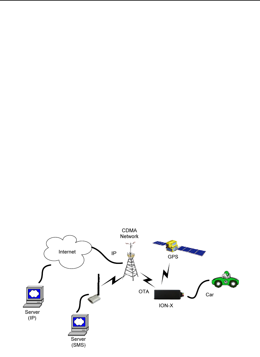
TheARROW‐Cisaself‐containedvehicletrackingdevicethatcombinesGPSlocationwith
CDMAconnectivity.
TheArrow‐Cdeviceserieshas5productions:AR‐2CX/SR‐2CU/S4N‐2CU/S6N‐2CU/KT‐2CU
Logically,theARROW‐Cappearstoauseroraserverapplicationasasingleendpointdevice.
Itcanbequeried,updatedandconfiguredeitherthroughaserialconnection,oranoverthe
airCDMAIPconnection,orthroughSMSmessaging.TheARROW‐Cpresentsitselfoverthese
connectionsasanenhancedcellularmodemwithattachedfunctionalelements.These
elementsinclude:
GPSlocationengine
2GeneralPurposeBidirectionalI/O(GPIO)pins
1Relaydrivepinoutput
SerialUARTport
Inputvoltagemonitor (optional)
Timers
Watchdoglockupprotection (Dedicatedwatchdogcircuitisoptional)
Factoryl oadoptionformotiondetection
AccesstotheseelementsandgeneralpurposeinterfacesisdonethroughanextendedAT
commandsetasdefinedherein.
Application scene:
ThisproductwillbedesignedbasedontheVIACBP8.2CDMA1X800M&1900MBaseband
chipset,whichincludesGPSfunctionality,ARMCPUandCDMAprotocol.Thisbaseband
externalconnection256Mserialflash,CDMA800M/1900M/GPSRFTransceiver,andRF
Frontendcircuit.
Thedevicewilluseonedualbandantenna(CDMA800&CDMA1900)andonededicateGPS
antenna.

ARROW‐CUserManual
4
Hardware Design
1.1 Basic Hardware
ItemsRequirement
BasebandChipsetVIACBP8.2C
RFTransceiverGRF6416
MemorySerialFlash64Mb
PSRAM128Mb
AirInterfaceCDMA20001x,GPS
FrequencyCDMA20001x:800MHz,1900MHz
AntennaInternalAntenna(800M&1900M)
GPSAntennaDedicatehighperformanceceramicantenna
UIMrequirementNo‐UIMmode,UIMcardconnectoroptional
InterfaceUARTTX
UARTRX
12VDCInput(1Acurrent)
RelayDrive(12VOutput,500mAcurrent)
GPIO1
GPIO2
BatteryMonitorinternalanaloginputscaled(Optional)
BuildinbatterymanagerSupported
DedicateTimersNo
WatchdogSupported(DedicateWatchdogisOptional)
MotionDetectOptional(GPS/Sensor)
LED2LEDSupported
2LEDs(oneisRED,oneisGreen)
BatteryBuild in battery(80MAH Lion)
WorkingTime4hours
PowerswitchNo
PowerCablecolor8 colors
PowerCableconnectortype8 pin
PowerConsumption< 5Watts
TheARROW‐CprovidessupportforspecializedhardwarefeaturesthroughextendedAT
commands.Thefeaturessupportedincludethefollowing.
GPS
ThemajorfunctionalityoftheGPSmoduleistocomputethecorrelationresultsbetweenthe
incomingsignalandtheselectedPRNcodebasedoncertainCarrierDopplerFrequency,Code
DopplerFrequency,codephase,carrierphase,andtheparticularsatellitethemoduleis
trackingoracquiring.
GPIO

ARROW‐CUserManual
5
TwoGPIOpins,GP1andGP2,arepresentedtotheexternalenvironmentonthemain
connector.Theyaregeneralpurposebidirectionallinescapableofprovidingsystem
interruptstogenerateareportordrivelogiclevelstoexternaldevices.Theselinesare2.8V
logiclevelandare15Vtolerant.Thesepinsdefaulttoinput.GP1ispulleddownrepresenting
0whendisconnected;GP2ispulleduprepresentinglogical1whendisconnected.They
shouldbeassertedtoaknownvalueifused.GP1isintendedtouseforIgnitionSensing.
LED’s
TwoLEDstatusindicatorsareprovidedtoverifycorrectinstallationandoperation.The
statusLEDsarecolorcodedanddirectlyconveythestatusoftheCDMAandGPSsubsystems
asdescribedinthetablebelow.Theirvalidoperationalsoindicatesoperationalstatusand
power.
LED Function Status
Red GPS On:GPSsatellitesacquiredand
Locked
FlashSlow:GPSsatellitesearchis
inprogress
Off:NopowerorGPSsubsystem
fault
Green CDMA/CDMAConnection On:IndicatesCDMAconnectionis
made
FlashSlow:CDMAsubsystem
initializedbutnoconnection
FlashFast:CDMAinitializationin
process
Off:NopowerorCDMA
subsystemfault
TheARROW‐CprovidesusercontrolallowingtheLEDstobeextinguishedonceinstallationis
verified.ThisfeaturereducespowerandfurtherconcealstheARROW‐CTrackerfrom
untrainedpartieswishingtodefeatitsoperation.
UART
AUARTportisprovidedforATcommandanddatainteractionandoptionallyforapplication
specificcontrol.Wheninpowerdownmode,acharactermustbesenttotheUARTfirstto
wakeitup.Theportwillstayawakefor5secondsafteranycharacterreceived.
RelayDriver
A500mAsinkcapableoutputpinisprovided.Thispinismeanttodrivearelaycoilindented
tointerruptthestartersolenoidrelayfortheignitioncircuittoacar.
BatteryMonitor
ThebatterymonitorisinternalanaloginputscaledsuchthattheDCvalueofthepowerinput
pintotheARROW‐Csystemismeasured.Thisvalueisscaledtospanthemostsignificant8
bitsoftheA/Dandconsequentlycoversascalefrom0to25.5Volts.
Timers
TimersresidentontheCDMAbasebandchipgenerateperiodicinterruptsforpowerdown
wakeup,watchdogsupport,reportgenerationandothertimerrelatedfunctions.Report
timersaresupportedbyrelatedATcommandandcausegenerationofperiodicreports.

ARROW‐CUserManual
6
Watchdog
CBP8.2chipsetprovideinternalsoftwareWatchdog,andaphysicallydedicateWatchdog
circuitrequirementisoptional.
MotionDetect(Option)
Afactorypopulatesoptionformotiondetectorisprovided.Ifpopulatedatthetimethe
ARROW‐Cismanufactured,thisoptionwillworkwithfirmwarepowerdownoptionstokeep
theARROW‐Cinaverylowpowerdownstateuntilmotionisdetected.Uponwakening,a
reportcanthenbegenerated.
1.2 Basic RF Performance
ItemsRequirementsRemark
TRPfreespace>=20dBmTRPfreespace
TISfreespace<=‐104dBmTISfreespace
Antennaloss<=‐3dBTRP‐TXPowerConducted
AntennaLoss<=‐3dBRXreceivesensitivityconducted–
TIS
BoardRFSpecification
CellularBandRX
Frequencyrange869MHz~894MHz
Sensitivity‐108dBm(FER≤0.5%)
Dynamicrange‐25~‐108dBm(FER≤0.5%)
SingletoneDesensitization‐102.4dBm(FER≤1%,‐30dBm@±900KHz)
IntermediationSpurious
ResponseAttenuation
‐102.4dBm(FER≤1%,‐43dBm@±900KHz/±1700KHz)
‐91.4dBm(FER≤1%,‐32dBm@±900KHz/±1700KHz)
‐80.4dBm(FER≤1%,‐21dBm@±900KHz/±1700KHz)
ConductedSpurious
Emission
<‐76dBm/1MHz(RXband)
<‐61dBm/1MHz(TXband)
<‐47dBm/30KHz(otherfrequency)
CellularBandTX
Frequencyrange824MHz~849MHz
MaximumFrequencyerror±300KHz
Maximumoutputpower23~30dBm
Minimumcontrolledoutput
power
<‐50dBm
Standbyoutputpower<‐61dBm
Codedomainpower
Thecodedomainpowerineachinactivecodechannel
shallbe23dBormorebelowthetotaloutputpower
measuredonboththeIandQdatachannelcombined.
Timereference±1.0uS
Waveformquality>0.944
Rangeofopenloopoutput(test1:-25dBm/1.23MHz)-47.7±9.5dBm
20 ~ 24.5dBm

ARROW‐CUserManual
7
power(test2:-60dBm/1.23MHz)-7.7±9.5dBm
(test3:-93.5dBm/1.23MHz)20.3±9.5dBm
Conductedspuriousemission
‐42dBc/30Khzor‐54dBm/1.23MHz
(|Δf|:1.25MHz~1.98MHz)
‐50dBc/30Khzor‐54dBm/1.23MHz
(|Δf|:1.98MHz~4.00MHz)
<‐36dBm/1kHz
(|Δf|>4MHz,9KHz<f<150KHz,)
<‐36dBm/10kHz
(|Δf|>4MHz,150kHz<f<30MHz,)
<‐36dBm/100kHz
(|Δf|>4MHz,30MHz<f<1GHz)
<‐30dBm/1MHz
(|Δf|>4MHz,1GHz<f<12.75GHz)
PCSBandRX
Frequencyrange1930MHz~1990MHz
Sensitivity‐108dBm(FER≤0.5%)
Dynamicrange‐25~‐108dBm(FER≤0.5%)
SingletoneDesensitization‐102.4dBm(FER≤1%,‐40dBm@±1250KHz)
IntermediationSpurious
ResponseAttenuation
‐102.4dBm(FER≤1%,‐43dBm@±1250KHz/±2050KHz)
ConductedSpurious
Emission
<‐76dBm/1MHz(RXband)
<‐61dBm/1MHz(TXband)
<‐47dBm/30KHz(otherfrequency)
PCSBandTX
Frequencyrange1850MHz~1910MHz
MaximumFrequencyerror±150KHz
Maximumoutputpower23~30dBm
Minimumcontrolledoutput
power
<‐50dBm
Standbyoutputpower<‐61dBm
Codedomainpower
Thecodedomainpowerineachinactivecodechannel
shallbe23dBormorebelowthetotaloutputpower
measuredonboththeIandQdatachannelcombined.
Timereference±1.0uS
Waveformquality>0.944
Rangeofopenloopoutput
power
(test1:‐25dBm/1.23MHz)‐50.7±9.5dBm
Conductedspuriousemission(test2:‐60dBm/1.23MHz)‐10.7±9.5dBm
(test3:‐91.3dBm/1.23MHz)20.3±9.5dBm
20 ~ 24.5dBm

ARROW‐CUserManual
8
‐42dBc/30Khzor‐54dBm/1.23MHz
(|Δf|:885KHz~1.98MHz)
‐54dBc/30Khzor‐54dBm/1.23MHz(|Δf|:
1.98MHz~4.00MHz)
<‐36dBm/1kHz(|Δf|>4MHz,9KHz<f<150KHz)
<‐36dBm/10kHz(|Δf|>4MHz,150kHz<f<30MHz)
<‐36dBm/100kHz(|Δf|>4MHz,30MHz<f<1GHz)
<‐30dBm/1MHz(|Δf|>4MHz,1GHz<f<12.75GHz)
GPS
AGPSSupport
Embedded AGPS software supporting an internal GPS
subsystem solution
E911FCCmandatedphase1andphase2(optional1)
FrequencySupport
L1-band (1.57542GHz)
Channels: 210 PRN, 66 Search, 22 Simultaneous
tracking
Sensitivity
Sensitivity (UHIS):
Tracking: -156dBm
Reacquisition: -153dBm
Acquisition: -144dBm
TrackingTimeRequirement
Acquisition time:
Hot: <2s
Warm: <30s
Cold: <60s
Reacquisition: 2s - 10s Depends on signal level
1.3 Certification and Safety
ItemsRequirement
DropDesign1.2meter6directionstandarddroptest
TemperatureRange‐40to85°COperation
‐50to+100°CStorage
Humidity:20%to90%Operation
10%to95%Storage
Altitude:‐500to+18,000m
VehicleISOTestISO+7637‐2‐2004;ISO+7637‐3‐2007;ISO_10605‐2008;
ISO+16750‐2‐2010
FCCCertificationFCC47CFRPart15andPart18
SafetyULListing
OthersOperatorRequirementIndustryCanada/AT&T(optional)
ESDRequirement15KVnon‐conductive

ARROW‐CUserManual
9
2 Software Features
2.1 Basic Software
ItemsRequirement
AirInterfaceCDMA20001x800/1900MHz;GPS
1xData Supported
IPStackIpv4/IPV6
UpgradeMethodRemoteupdate /PCtool
RUIMOptional
CompatiblewithNone‐RUIMSupported
RemoteUpdateSupported
PowerModesSupported
ATCommandSupported
ReportSupported;3000records
DriverGPIO,LED,GPS,UART
GPIOsInterruptforDoorOpenDetect,Ignition
Status
LEDsGPSStatus,CDMAStatus
WatchDogSupported(CBP8.2integrated)
ResetSoftreset
StartupBannerSupported
2.2 Remote Update
TheARROW‐CsupportsOTAfieldupgradesoftheARROW‐Cresidentapplication.Anoverthe
airTFTP(TrivialFileTransferProtocol)connectionismadeoveraUDP/IPconnection.A
replacementfileisthentransferredfromaservertotheARROW‐Candthatfilereplacesthe
previousapplicationimage.
2.2.1 Auto Execute
TheAutoExecuteUtilitycopiesthecontentsoffilesystem.exfintosystemexecutableRAM
andexecutesitfromthere.Thisfileisthefactorydefaultapplication.Anotherfilenamed
custom.exfcanbeloadedintothefilesystem.
AutoExecutewilllookfirstforafilenamedupdate.exfandloadandexecutethatinplaceof
custom.exfifitexists.Ifupdate.exfexecutessuccessfully,thepreviouscopyofcustom.exfis
deletedfromthefilesystemandupdate.exfisrenamedtocustom.exf.
2.3 Power Modes
TheARROW‐Cdevicesupportsseveralpowermodesthataresetbythepowermode
command.Infullpowermodethecellularsubsystemwillmaintainapersistentcellular
connectionwheneverserviceisavailableaswellasanIPconnectionwhereavailable.
Anyhardwareorsoftwareresetwillinterruptanypowermodeandreturnthedevicetofull
powermode. Insummary,theconditionspermanentlyrestoringfullpowermodeinclude:

ARROW‐CUserManual
10
Powercycle
Watchdogtimeout
Resetcommand
CDMAphonecallreset
SMSorUARTpowermodecommand
Motiondetect(ifdetectorinstalledandenabled)
Wheninapowerdownmode,thefollowingresourceswillcauseinterruptsthatwillwake
theARROW‐Candcauseittoattemptcompletethefunctionassociatedwiththeinterrupt.
Simultaneousinterruptswillcausesequentialcompletionofeachassociatedfunction.These
interruptsinclude:
Reporttimer
GPIOchange
Batterythreshold
Heartbeat
Watchdog
Power ‐up
Therelatedinterruptfunctionwillbeattemptedforatotaldurationsettheassociated
parameterinthepowermodecommand.
2.4 AT Command
ARROW‐CcommandsareATextensionsspecifictoARROW‐Cdevices.Theyarecloselybased
oncommandsthatareassimilaraspossibletootherindustrycommondevicesandare
essentiallysubsetsofstandardARROW‐Ccommands.CommoncommandsusedwithCDMA
modemssupportingIPconnectivityarenotincludedwithintheARROW‐Ccommandset
extensions.Thesecommandsareleftintheirnativestructure,asdefinedbytherespective
basebandCDMAchipsupplierwhichproductalreadyinuse.
CommandSummary
ThefollowingcommandsarehighlyspecializedtotheTALONCV001.Thecommandslisted
areintendedtobesimilartocounterpartsfoundincommonCDMAmodemcommand
extension.
1.AT+IONAA:Setappendmode
2.AT+IONACK:Setacknowledgementmode
3.AT+IONAPN:SetAPN
4.AT+IONBIN:Readthefactorycoresoftwareversion(readonly)
5.AT+IONBZ:Buzzersetting
6.AT+IONCV:Configurationversion
7.AT+IONDI:Setdistanceintervalinterrupt

ARROW‐CUserManual
11
8.AT+IONDTE:Setdrivingtimeevents
9.AT+IONFR:Restorefactorydefaults
10.AT+IONGF:Setgeofenceborders
11.AT+IONGFH:Setgeofencearoundcurrentlocation
12.AT+IONGPIO:GPIORead/Write
13.AT+IONGS:GPSStatereport
14.AT+IONHB:Heartbeat
15.AT+IONHC:HeadingChange
16.AT+IONINFx:Listsysteminformationsegments
17.AT+IONIP:SettargetserverIPaddressandportnumber
18.AT+IONIPC:IPChangereport
19.AT+IONIS:IgnitionState
20.AT+IONLT:LEDs’TimingandIntensity
21.AT+IONLPORT:SetthelocalIPportnumber
22.AT+IONNR:SettimebeforeIPsessionisclosedandrestarted
23.AT+IONNW:Setwatchdogtimeoutifnonetworkfound
24.AT+IONPM:Setautopowerdownmode
25.AT+IONRF:ReportFormat‐ASCII/Binary
26.AT+IONRI:Setreporttimerinterval
27.AT+IONRM:ReportMask
28.AT+IONRN:Queuereportrecordfortransmission
29.AT+IONRR:Setresetreport
30.AT+IONRS:Resetsetting‐soft/hard,periodic
31.AT+IONSD:SetSMSresponsedestination
32.AT+IONSI:Setinterrupt
33.AT+IONSQ:Setqueuelength
34.AT+IONSR:Setrelaydriver(GP3)statehighorlow
35.AT+IONSV:Readthefactoryapplicationsoftwareversion(readonly)
36.AT+IONTA:TowAlert
37.AT+IONTID:CDMAtowerIDandlocationdata
38.AT+IONUA:UpdateapplicationfirmwareOTA

ARROW‐CUserManual
12
39.AT+IONUC:UpdateconfigurationfilesOTA
40.AT+IONVO:VirtualOdometer
41.AT+IONVTO:VirtualTripOdometer
2.5 Report
TheARROW‐Ccapturesdataandformsareportrecordwiththatdata.Thisisasingledata
structureintendedtocontainallofthetypicallyusefuldataontheTALONCV001.Other
informationcanbequeriedseparatelyusingseparateATcommands.
ReportsarealwaysgeneratedbyinterruptsregardlessofwhetherornotthereisaGPSlock.
Ifnolockhaseverbeenattainedsincehardwarereset,defaultvaluesof0arereturnedfor
allGPSfields.Ifalockhasbeenattainedandlost,thereportwillcontainthelastvalidGPS
dataincludingthetimestampofthatdata.
BaseRequirements:
1. Areportisgeneratedinresponsetoeitheraninterrupteventorinresponseto
executionofassociatedATcommandsexplicitlyrequestingone.
2. GPScoordinatesarestoredinreportsassignedhexvaluestosavespace.
3. Toreducedatatransmissioncosts,thedatawithinareportrecordcanbemasked
andremovedbeforeitistransmitted.
4. Everyreporthasatagandeachenabledinterruptoreventgeneratesaseparate
report.Thereporttagsindicatethecauseofthegeneratedreport,whichcanbean
interrupt,aneventorinresponsetoacommand.
2.6 Reset
Thereisaninternalsoftreset.
2.6.1 Context Preservation
WhenaresetiscausedbytheNetworkWatchdogorbytheResetcommand(modes0,1),
thecontextofthesystemisbeingpreservedandisrestoredafterthereset.Thecontext
includesalltheperiodictimers,thereportqueue,theodometer,etc.Thisallowstoresetthe
unitasatroubleshootingmeasureeitherperiodicallyorduetoNetworkWatchdogwithout
losingreportsthatarealreadyinthequeueorarependingonrunningtimers.Notethatthe
resetprocessmaycause1‐2minofinaccuracyinthetimersandshouldnotbeconsideredas
veryprecise.
Modes8/9oftheIONRScommandperformsoftandhardresetrespectivelywithout
preservinganycontext.Factoryreset(IONFR)alsodoesnotpreserveanycontextofthe
system.
2.7 Startup Banner
AfteraresetastartupbannerisprintedthroughtheUARTonly.Theformatandcontentof
thebannershownbelow:
FW:<firmware version>; BIN:<bin version>; MEID/ESN:<MEID/ESN>
APN1:<apn1 name>; IP:<IP>:<port>;LPORT:<lport>
RI:<s,v,t>; DTE:<t1,t2,t3>; DI:<t>; HB:<t>; NR:<t,c,r>; RS:<a,t,r>

ARROW‐CUserManual
13
3 Test Method
3.1 Hardware
TestItemDescription
BasebandFunctionTest• PowerInputTest
• PowerConsumptionandCurrentTest
• HeatDissipationTest
• UARTStabilityTest
• GPIOLevelTest
• LEDStabilityTest
• DropDownTest
• ESDTest
• High/LowTemperatureTest
• HumidityTest
RFTest• RFPerformanceTest
• GPSPerformanceTest
• AntennaPerformanceTest
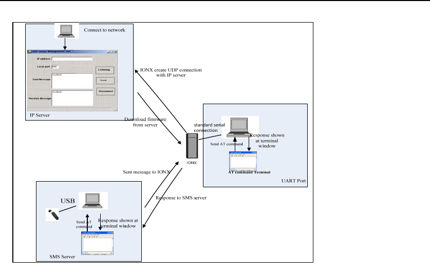
3.2 Software Test
TestEnvironmentConstruct
messageTestenvironment
1.usbdongleandPCasmessageserver
2.sendmessagetoIONX
UDPTest environment
1.connectdongletoPCandcreatedialupasipserver
2.IONXcreateIPconnectiontoserver
UARTTest environment
1.connectIONXtopcwithcomserialcable
2.openTermina ltoolandsendatcommand
3.reponsecanbeshownatterminalwindow
ARROW‐CUserManual
14
FCC Statement
This equipment has been tested and found to comply with the limits for a Class B digital device,
pursuant to Part 15 of the FCC Rules. These limits are designed to provide reasonable
protection against harmful interference in a residential installation. This equipment generates
uses and can radiate radio frequency energy and, if not installed and used in accordance with
the instructions, may cause harmful interference to radio communications. However, there is
no guarantee that interference will not occur in a particular installation. If this equipment does
cause harmful interference to radio or television reception, which can be determined by turning
the equipment off and on, the user is encouraged to try to correct the interference by one or
more of the following measures:
-- Reorient or relocate the receiving antenna.
-- Increase the separation between the equipment and receiver.
-- Connect the equipment into an outlet on a circuit different from that to which the receiver is
connected.
-- Consult the dealer or an experienced radio/TV technician for help.
Changes or modifications not expressly approved by the party responsible for compliance
could void the user's authority to operate the equipment.
This device complies with part 15 of the FCC Rules. Operation is subject to the following two
conditions:
(1) This device may not cause harmful interference, and
(2) this device must accept any interference received, including interference that may cause
undesired operation.
The antenna(s) used for this transmitter must be installed to provide a separation distance of at least 20
cm from all persons and must not be co-located or operating in conjunction with any other antenna or
transmitter.