Connected AG20 GPRS GPS Tracker User Manual Reset switch
Connected Holdings LLC GPRS GPS Tracker Reset switch
User manual

Confidential Preliminary – Subject to Change
2010 China Mark, Ltd. T/A Montage Asia Page 1 of 19
Product Specification
For the
Arrow Vehicle Tracking Device
By
KEELIN
December 5, 2012
Authorized Recipients
Executive management as provided to and are bound by a Non Disclosure Agreement
(NDA) in favor of Montage Asia or its agent and preventing disclosure or misuse of the
confidential information herein.
The information presented in this document is strictly confidential and contains
trade secrets and other confidential information that are the exclusive property of
Montage Asia, its parent, subsidiaries or agents.

Confidential Preliminary – Subject to Change
2010 China Mark, Ltd. T/A Montage Asia Page 2 of 19
Revision History
Revision
Date
Description

Confidential Preliminary – Subject to Change
2010 China Mark, Ltd. T/A Montage Asia Page 3 of 19
Scope
This document sets forth the basic technical requirements and feature set for the ion
tracking device.
Description
The Arrow Tracker is a self contained, expandable, integrated commercial grade vehicle
tracking device that uses GPS satellite location in combination with a quad band
GSM/GPRS cellular radio connection to report that location. ion is optimized for
reliability, cost and size. However, it remains highly flexible and capable of addressing
diverse and specialized requirements through a novel expansion arrangement.
All antennas including the GPS patch and GSM helical antenna are internal to the device.
Data reporting can be initiated by a command center or by the tracker itself via
GSM/GPRS, SMS or UDP pathways.
The Arrow is unique in that it is intrinsically expandable. A screw fastened expansion
door secures SIM card access as well an expansion connector and daughter board cavity.
This port supports small integrated daughter boards with features such as motion
detection, acceleration measurement or radio expansion through standards such
Bluetooth, Zigbee or WiFi.
The Arrow also supports functional expansion by a side mount adapter. This adapter
supports addition of physically large devices such as very large capacity batteries.
The Arrow is based on chip level design as opposed to using a module with an external
processor. The application software executes on the base level Central Processing Unit
(CPU) under direct Operating System (OS) control. This approach provides a much more
reliable, lower power and faster response than module/processor architectures. Unlike in
common module/processor based designs; the ion design allows direct operating system
access by the application, thus mitigating the need for a redundant external processor.
For added redundancy against system lockup, a physically separate, dedicated watchdog
chip oversees the ion system operation. If the system does not maintain the watchdog
chip through programmed reporting, the system power is cycled and a new satellite and
cellular connection is established.
The Arrow Tracker can be provisioned for UDP and SMS data services for both
application command and data transactions within the 850, 900, 1800 and 1900 MHz
GSM bands. Network provisioning is done with standard SIM cards. For added
safeguard against network connection loss, a hardware ion endpoint reboot can be
initiated by simply calling the provisioned phone number from a previously established
Caller ID (CID).
Flexible I/O includes 2 bidirectional General Purpose Input Output (GPIO) ports that can
also be assigned as a software Universal Asynchronous Receiver Transmitter (UART)
port. A separate dedicated UART port is provided for general use as well as development
and programming support. A high current relay drive is provided for starter motor relay
control or general purpose drive (current sink only).

Confidential Preliminary – Subject to Change
2010 China Mark, Ltd. T/A Montage Asia Page 4 of 19
The power input, ground and GPIO signals that are present on the main 8 pin external
vehicle connector are also available on the 8 pin internal expansion connector. On the
internal connector, there is also a unique battery supply pin that supports connection of a
rechargeable battery.
Over The Air (OTA) program updates are supported through Firmware Over The Air
(FOTA) protocol. This server based update system is licensed from HP.
All inputs are electrically hardened against overvoltage and over current conditions
present in automotive environments. This includes transient electrical noise and Electro
Static Discharge (ESD). The power input is further protected against over current with
an internal, self resetting fuse.
The Arrow enclosure and its features are secured using M2 sized metal fasteners for
rugged mechanical performance. The daughter board expansion and vehicle interface are
achieve through robust, commercial grade, pin to wire header connections (in contrast
with leaf contacts commonly used in cell phones and other portable non-industrial
systems).
The Arrow is physically disguised to appear to an untrained observer to be a nondescript
part of the cabling system. It is a small black box with unremarkable features. Two LED
status indicators are provided to verify correct installation and initial operation. A unique
feature extinguishes those status indicators 24 hours after an initial power up sequence.
This feature further conceals the ion Tracker from untrained parties wishing to defeat its
operation. The status indicators resume normal operation after the primary power has
been removed for any length of time. This allows for maintenance to be initiated by
simply disconnecting and then reconnecting power. This feature may be disabled as a
factory option.
The Arrow Tracker uses a simple cabling arrangement and supports splicing into an
OBDII extension for power. Connection to the vehicle is made through a 3mm pitch
rectangular header connection common to the automotive market.
As with all GPS location devices, the ion should be installed in a vehicle such that it has
an unobstructed view of the sky during normal operation. Double sided foam tape can be
used to secure the surface not facing the sky if needed.

Confidential Preliminary – Subject to Change
2010 China Mark, Ltd. T/A Montage Asia Page 5 of 19
Bullet Specifications
________________________________________________________________________
Cellular: 850/900/1800/1900 MHz Quad band
GSM/GPRS Protocol CS-1, CS-2, CS-3 and CS-4
Output power:
Class 4 @ 850/900MHz
> 24dB @ 850/900MHz (OTA TRP)
Class 1 @ 1800/1900MHz
> 26.5dB @ 1800/1900MHz (OTA TRP)
Sensitivity:
< -107dBm @ 850/900MHz (Chip)
< -101dBm @ 850/900MHz (OTA TIS)
< -106dBm @ 1800/1900MHz (Chip)
< -103.5dBm @ 1800/1900MHz (OTA TIS)
Antenna:
Wire helix
Meets minimum AT&T TRP/TIS requirements
________________________________________________________________________
Services: GPRS Multi slot class 12
SMS (Text):
Point to point mobile originated and terminated
Transport over GPRS
UDP data
DNS address resolution
Dual APN access
GSM circuit switched hard reboot (CID qualified)
________________________________________________________________________

Confidential Preliminary – Subject to Change
2010 China Mark, Ltd. T/A Montage Asia Page 6 of 19
________________________________________________________________________
GPS: L1-band (1.57542GHz)
Channels:
210 PRN
66 Search
22 Simultaneous tracking
Sensitivity (TIS):
Tracking: -45dBm
Reacquisition: -40dBm
Acquisition: -40dBm
Sensitivity (UHIS):
Tracking: -165dBm
Reacquisition: -158dBm
Acquisition: -149dBm
Acquisition time:
Hot: <1.5s
Warm: <34s
Cold: <35s
Reacquisition: <1.0s
WAAS:
Position: <3m
Velocity: >0.1m/s
Acceleration: >0.1m/s2
Altitude: 18,000m (max)
Velocity: 515m/s (max)
Acceleration: 4G (max)
32 Geo fences
25x25x4mm patch antenna
________________________________________________________________________

Confidential Preliminary – Subject to Change
2010 China Mark, Ltd. T/A Montage Asia Page 7 of 19
________________________________________________________________________
I/O: One main port and one internal expansion port
All pins are 16V tolerant and ESD protected
Main Port:
8-Pin, 3mm pitch header
3-Pins 2.8V GPIO
2-Pin 2.8V serial UART
TX output
RX input
1-Pin relay drive
-500mA drive
TVS overvoltage protection
1-Pin power input:
1.5A resetting fuse
TVS overvoltage protection
1-Pin ground
Internal expansion:
8-Pin, 1.25mm pitch header
3-Pins 2.8V I/O common with main GPIO port
2-Pins 2.8V I/O GPS serial port (test only)
1-Pin power input common with main port
1-Pin ground common with main port
1-Pin Li+ battery input to device
SIM: 6-Pin keyed insertion
LED:
Red GSM status
Green GPS status
Battery voltage measurement
Ambient temperature measurement
________________________________________________________________________

Confidential Preliminary – Subject to Change
2010 China Mark, Ltd. T/A Montage Asia Page 8 of 19
________________________________________________________________________
Power: Vin:
9.0 – 16.0VDC (Main)
3.5 – 4.2VDC (Expansion)
Main:
Full Shutdown: < 50µA
Standby: < 800µA (GSM Idle)
GPS acquisition: < 8.0mA (GSM Idle)
GPS tracking: < 6.0mA (GSM Idle)
GSM dedicated: < 92.0mA (GPS Off)
GPRS max power: < 183.0mA (GPS Off)
Peak instantaneous < 740mA
Exp: 2.45 x Main
________________________________________________________________________
Software: Native ARM processor execution
Montage proprietary application
Extended AT command interface
Easily configured reports to minimize data transport costs
Based on proven GSM/GPRS modem stack
Lockup protection:
Independent watchdog with power cycle reset and reboot
GSM circuit switched reset
Flash memory:
8MB for application and data storage
2500 report log entries
Serial port update
Over the air update
Development:
Complete C language tool chain
Serial to USB COM port support (custom supplied cable)
________________________________________________________________________

Confidential Preliminary – Subject to Change
2010 China Mark, Ltd. T/A Montage Asia Page 9 of 19
________________________________________________________________________
Physical: Design: Nondescript design
Color: Black
Texture: Light
Material: Acrylonitrate Ethylene Styrene + Polycarbonate
Size: 91*39.4*12.8(mm)
Weight: TBDg
Fasteners: M2
Expansion port:
Side mount
Top hatch
SIM: Keyed retainer socket
________________________________________________________________________
Environment: Temperature:
-20 to 75° C Operation
-50 to +100° C Storage
Humidity:
20% to 90% Operation
10% to 95% Storage
ESD: 10KV immune on all user accessible surfaces and ports
Altitude: -500 to +18,000m
Shock: 25G
Vibration: TBD
________________________________________________________________________
Approvals: FCC 47 CFR Part 15 and Part 18
Industry Canada
UL Listing
PTCRB
AT&T
________________________________________________________________________
Shock: 25G
Vibration: TBD
________________________________________________________________________
Standards: ISO 10650
ISO 16750
ISO 7637
________________________________________________________________________

Confidential Preliminary – Subject to Change
2010 China Mark, Ltd. T/A Montage Asia Page 10 of 19
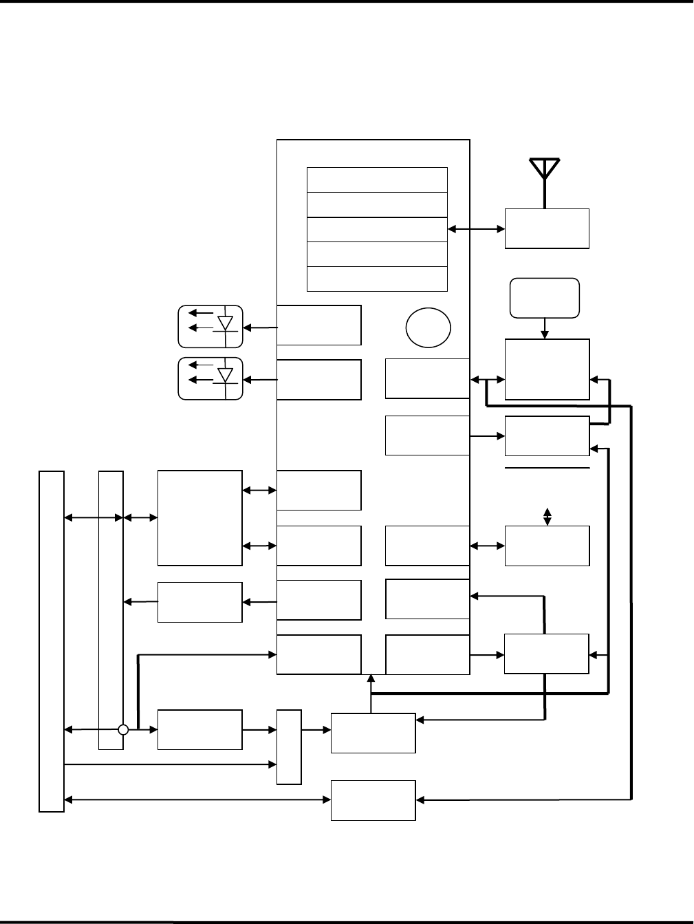
Hardware Architecture
Figure 1 shows a high level block diagram of the device system hardware. The core
architecture is defined by the single chip cell phone and GPS module. The cell phone
chip executes the software application and Operating System on the internal ARM CPU.
The associated chips provide the complete functionality required with the exception of
the peripheral resources shown.
Confidential Preliminary – Subject to Change
2010 China Mark, Ltd. T/A Montage Asia Page 11 of 19
Single Chip Phone
ARM
Cellular Base Band
Figure 1
Arrow Hardware Architecture Block Diagram
Memory Interface
GSM
Status
GPIO
Signal
Conditioning
GPIO
GSM RF
Front End
GPS
Module
UART
Power
Regulator
DC/DC
Converter
UART
Power
Conditioning
Patch
Antenna
Antenna
8-Pin 3mm (Main)
Temp
RF Interface
GPIO
Relay
Driver
Watchdog
Controller
GPIO
Reset
8-Pin 1.25mm (Internal Expansion)
Switch
Timing
SIM
A/D
Red
Green
GPIO
ESD
Protection
ESD
Protection

Confidential Preliminary – Subject to Change
2010 China Mark, Ltd. T/A Montage Asia Page 12 of 19
B
o
o
t
L
o
a
d
e
r
Software Architecture
The application software resides in system flash memory and operates directly under
control of the native OS. Arrow does not use an external applications processor.
Structure
Figure 2 shows a high level block diagram of the basic architecture. The OS is closely
knit with a debugger allowing for code development, maintenance and updates over the
serial debug port. The boot loader provides control over all code and configuration
memory. The watchdog is a dedicated hardware device that will issue a hardware reset to
the unit in conjunction with a power cycle operation if it is not maintained by a periodic
ping from the application program.

Confidential Preliminary – Subject to Change
2010 China Mark, Ltd. T/A Montage Asia Page 13 of 19
Features
Arrow acts like a GSM modem and responds to AT commands issued to it from either a
physical serial port connection or to AT commands issued to it through SMS or a UDP
connection.
With regard to text messages, ion “reads” all of its own text messages and tries to
interpret each message as an AT command. SMS text may be sent to an endpoint
through a CSD or GPRS connection interchangeably.
Key superset functions outside that of typical GSM/GPRS modems are required to
support intrinsic ion Features. These include:
Automatic field lockup recovery
o Dedicated hardware watchdog with power and reset cycle
o GSM Circuit Switched Data (CSD) commands
Hard reset
Restore factory defaults
Instantiate code download using FOTA
Set Caller ID (CID) qualifier
Specialized GPS functions including
o GPS data reporting
o GPS module status reporting
o GPS power control
o Setup and monitor geographic fences
Device initiated UDP reporting
o Recurring schedule event
o Low battery condition
o Change in GPIO state
o Report record queue
o User defined IP addresses
o Geographic fence violation
Virtual AT command processor over SMS or a UDP connection
Data logging to flash
o OTA read of entries

Confidential Preliminary – Subject to Change
2010 China Mark, Ltd. T/A Montage Asia Page 14 of 19
o Circular buffer
OTA code update using FOTA
o 100% buffered
o Established 3rd party protocol
Application specific I/O
o Read/write digital
o Read battery voltage
o Read temperature
Dual APN support
Further details on the Arrow software features are available in the document titled: "AT
Command Specification for Arrow Tracker GPRS/GPS Tracking Device" and available
from the author of this document.
Confidential Preliminary – Subject to Change
2010 China Mark, Ltd. T/A Montage Asia Page 15 of 19
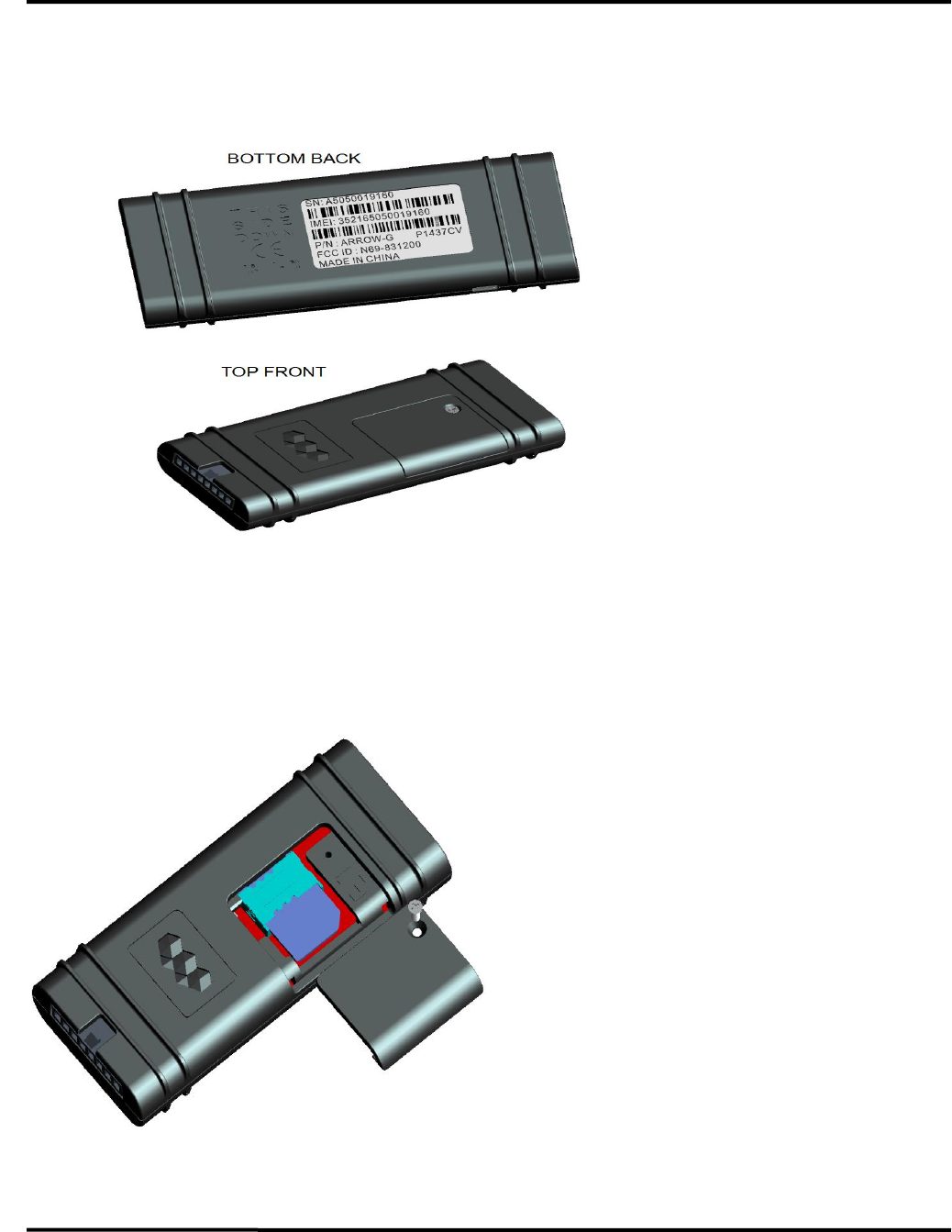
Physical Attributes
Figure 3 shows various views of the Arrow Tracker and its critical physical features.
For absolute locations of these features, the 3D CAD models should be referenced.
Confidential Preliminary – Subject to Change
2010 China Mark, Ltd. T/A Montage Asia Page 16 of 19
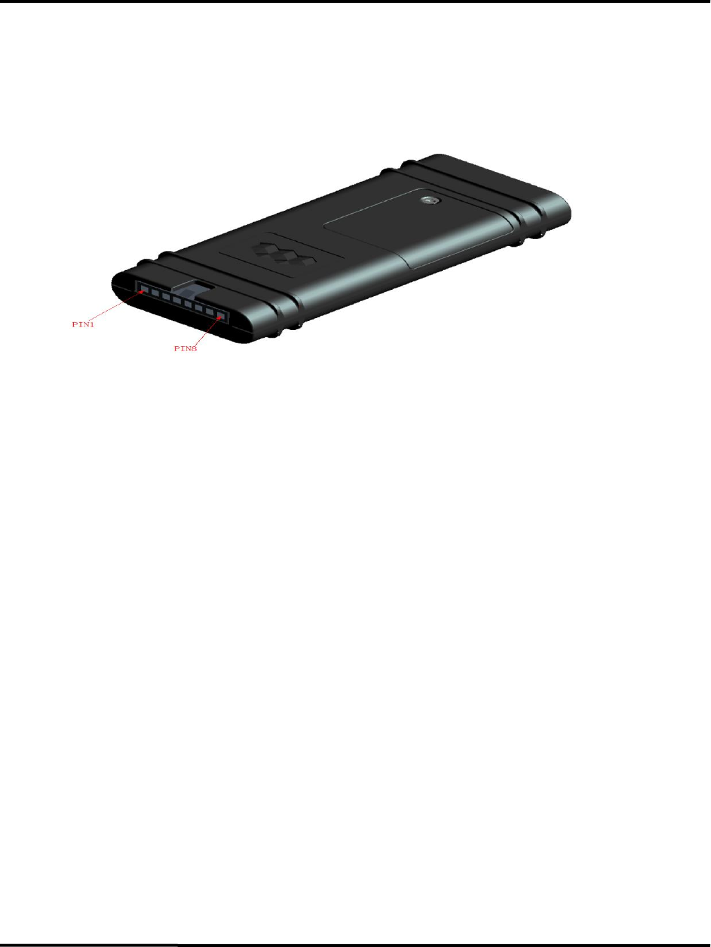
Signals
Interconnects are oriented as shown in Figure 5 looking into the front of the port.
Electrical properties are in the subsequent table. The connector is keyed and latched.

Confidential Preliminary – Subject to Change
2010 China Mark, Ltd. T/A Montage Asia Page 17 of 19
Main Signals
Pin
Number
Name
Description
Properties
1
GPIO1
Configurable as general input
or output
2.8V logic level, 15V tolerance,
equivalent circuit in NOTE
2
GPIO2
Configurable as general input
or output
2.8V logic level, 15V tolerance,
equivalent circuit in NOTE
3
RLY
Relay drive, connect relay coil
between pin 6 and this pin
500mA, 15V tolerance open drain
MOSFEET, TVS overvoltage protected
4
GPIO3
Configurable as general input
or output
2.8V logic level, 15V tolerance,
equivalent circuit in NOTE
5
TX1
General UART TX output,
also serves as debug serial out
2.8V logic level, 15V tolerance,
equivalent circuit in NOTE
6
RX1
General UART RX input, also
serves as debug serial in
2.8V logic level, 15V tolerance,
equivalent circuit in NOTE
7
VIN
Power input, connect to
positive side of battery power
3A PTC inline self resetting fuse, also
clamped to GND through 15V hold
TVS diode
8
GND
System ground, connect to
negative of battery power
Power and signal ground point
Confidential Preliminary – Subject to Change
2010 China Mark, Ltd. T/A Montage Asia Page 18 of 19
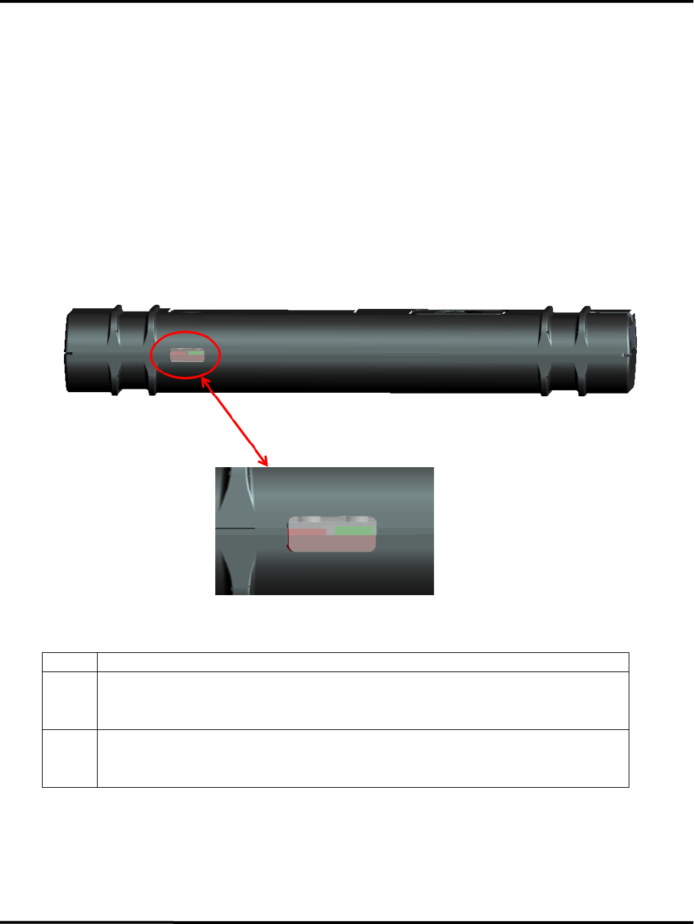
LEDs
The two status LEDs directly convey the status of the GSM and GPS subsystems as
described in the table. Indirectly, through their absence of a valid indication, they also
provide power and operational status. These LEDs are color coded and located as shown
in Figure 7.
LED
Status
Green
On: GPS satellites acquired
Flash: 250ms/250ms duty cycle indicates GPS satellite search is in progress
Off: GPS subsystem fault
Red
On: Indicates GPRS connection is made
Flash: 250ms/250ms duty cycle indicates GSM subsystem initialization
Off: GSM subsystem fault

Confidential Preliminary – Subject to Change
2010 China Mark, Ltd. T/A Montage Asia Page 19 of 19
FCC Statement
This equipment has been tested and found to comply with the limits for a Class B digital device,
pursuant to Part 15 of the FCC Rules. These limits are designed to provide reasonable protection
against harmful interference in a residential installation. This equipment generates uses and can
radiate radio frequency energy and, if not installed and used in accordance with the instructions,
may cause harmful interference to radio communications. However, there is no guarantee that
interference will not occur in a particular installation. If this equipment does cause harmful
interference to radio or television reception, which can be determined by turning the equipment
off and on, the user is encouraged to try to correct the interference by one or more of the
following measures:
-- Reorient or relocate the receiving antenna.
-- Increase the separation between the equipment and receiver.
-- Connect the equipment into an outlet on a circuit different from that to which the receiver is
connected.
-- Consult the dealer or an experienced radio/TV technician for help.
This device complies with part 15 of the FCC Rules. Operation is subject to the following two
conditions:
(1) This device may not cause harmful interference, and (2) this device must accept any
interference received, including interference that may cause undesired operation.
Changes or modifications not expressly approved by the party responsible for compliance could
void the user's authority to operate the equipment.
RF Exposure Warning Statements:
The antenna(s) used for this transmitter must be installed to provide a separation distance of at
least 20 cm from all persons during the normal operations.
IC STATEMENT
This device complies with Industry Canada licence-exempt RSS standard(s). Operation is subject
to the following two conditions: (1) this device may not cause interference, and (2) this device
must accept any interference, including interference that may cause undesired operation of the
device.
Le présent appareil est conforme aux CNR d'Industrie Canada applicables aux appareils radio
exempts de licence. L'exploitation est autorisée aux deux conditions suivantes : (1) l'appareil ne
doit pas produire de brouillage, et (2) l'utilisateur de l'appareil doit accepter tout brouillage
radioélectrique subi, même si le brouillage est susceptible d'en compromettre le fonctionnement.
In order to avoid the possibility of exceeding the IC radio frequency exposure limits, human
proximity to the antenna shall not be less than 20cm (8 inches) during normal operation.
Afin d'éviter la possibilité de dépasser les limites d'exposition aux fréquences radio de la IC CNR-
102, la proximité humaine à l'antenne ne doit pas être inférieure à 20 cm (8 pouces) pendant le
fonctionnement normal.