Connected AH10 HSPA GPS Tracker User Manual
Connected Holdings LLC HSPA GPS Tracker
UserManual.wiki
>
Connected
>
AH10 User Manual
User manual
Navigation menu
Upload a User Manual
Namespaces
Wiki Guide
HTML
PDF
Info
Views
User Manual
Discussion / Help
Navigation
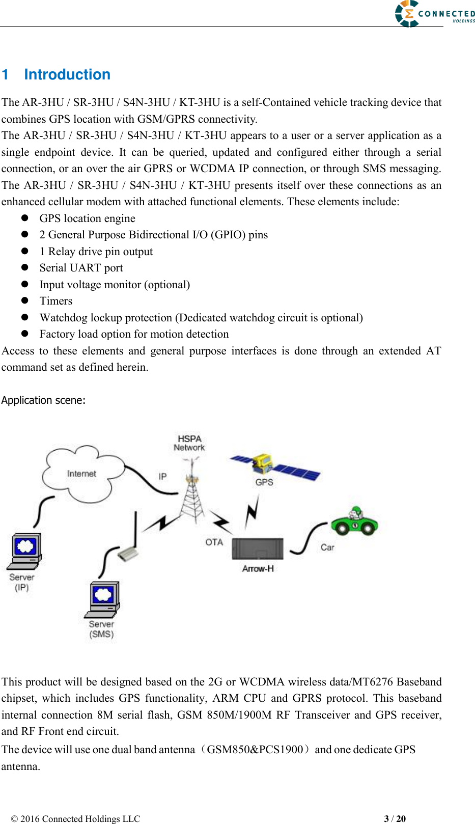
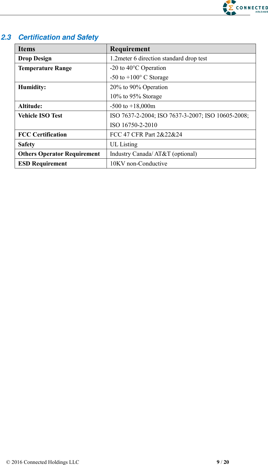
![© 2016 Connected Holdings LLC 4 / 20 2 Hardware Design 2.1 Basic Hardware Items Requirement Baseband Chipset MT6276A RF 2G Transceiver RF3235 RF 3G Transceiver RF7411TR7 Memory MCP_NAND 1Gb(x16) / mobile DDR 512Mb(x16) Air Interface Support for WCDMA, Class 12 GPRS, GPS Frequency 2G band support : 850MHz & 1.9GHz Support for 12 class GPRS 3G band support : Band 2 & Band 5Antenna Internal Antenna[850M&1900M]GPS Antenna UIM requirement No-UIM mode, GSM card connector optional Interface UART TX UART RX 12V DC Input(1A current) Relay Drive (12V Output ,500mA current) GPIO1 GPIO2 Battery Monitor internal analog input scaled (Optional) Build in battery manager Supported Dedicate Timers No Watchdog Supported Motion Detect Optional(GPS/Sensor) LED 2 LED Supported 2 LEDs(one is RED,one is Green) Battery Built in battery(80MAH Lion) Working Time 4 hours Power switch No Power Cable color 8 colors Power Cable connector type 8 pin Power Consumption < 5Watts The AR-3HU /SR-3HU / S4N-3HU / KT-3HU provides support for specialized hardware features through extended AT commands. The features supported include the following. GPS The major functionality of the GPS module is to compute the correlation results between the Dedicate high performance ceramic antenna](https://usermanual.wiki/Connected/AH10/User-Guide-3100690-Page-4.png)