Connected ALT01 GPS Tracker User Manual
Connected Holdings LLC GPS Tracker
User Manual

© 2017 Connected Holdings LLC 1 / 9
User Manual
AR-4LH
Vehicle Tracking Device
Author
Revision
Changes
Date
Tony_Wang
V01
Initial version
2017-08-27
The information presented in this document is strictly confidential and contains trade secrets
and other confidential information that are the exclusive property of Connected Holdings

© 2017 Connected Holdings LLC 2 / 9
Contents
1 Introduction 3
2 Hardware Design 4
2.1 Basic Hardware 4
2.2 Basic RF Performance 5
2.3 Certification and Safety 6
4 Test Method 7
4.1 Hardware 7
4.2 Software Test 7
Mechanical Structure(mm) 8
FCC Statement 9
IC STATEMENT 9
© 2017 Connected Holdings LLC 3 / 9
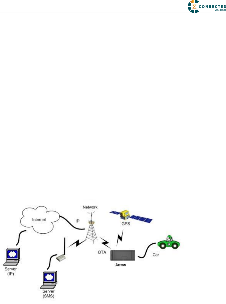
1 Introduction
The Arrow-L is a self-Contained vehicle tracking device that combines GPS location with
WCDMA/LTE connectivity.
The Arrow-L appears to a user or a server application as a single endpoint device. It can be
queried, updated and configured either through a serial connection, or an over the air LTE or
WCDMA IP connection, or through SMS messaging. The Arrow-L presents itself over these
connections as an enhanced cellular modem with attached functional elements. These
elements include:
GPS location engine
General Purpose Bidirectional I/O (GPIO) pins
Relay drive pin output
Serial UART port
Input voltage monitor (optional)
Watchdog lockup protection
Access to these elements and general purpose interfaces is done through an extended AT
command set as defined herein.
Application scene:
This product will be designed based on the MDM9207-1 baseband chipset, which includes
LTE Cat.1, WCDMA, and GPS functionality. The device will use one multi-band antenna and
one dedicated GPS antenna.

© 2017 Connected Holdings LLC 4 / 9
2 Hardware Design
2.1 Basic Hardware
Items
Requirement
Baseband Chipset
MDM9207-1
RF Transceiver
WTR2965
Memory
MCP_NAND 2Gb / mobile DDR2 1Gb
Air Interface
Support for WCDMA and LTE Cat.1
Frequency
4G band support : Band2/4/12
3G band support : Band2/5
Antenna
Internal Antenna
GPS Antenna
Dedicated high performance ceramic antenna
Interface
UART TX
UART RX
12V DC Input(1A current)
Relay Drive
GPIO1
GPIO2
Battery Monitor
internal analog input scaled (Optional)
Watchdog
Supported
Motion Detect
Sensor
LED
2 LED Supported
2 LEDs(one is RED,one is Green)
Battery
Built in battery(80MAH Lion)
Working Time
4 hours
Power Cable connector type
8 pin
Power Consumption
< 5Watts
The Arrow-L provides support for specialized hardware features through extended AT
commands. The features supported include the following.
GPS
The major functionality of the GPS system is to compute the correlation results between the
incoming signal and the selected PRN code based on certain Carrier Doppler Frequency,
Code Doppler Frequency, code phase, carrier phase, and the particular satellite the system is
tracking or acquiring.
GPIO
The GPIO pins are presented to the external environment on the main connector. They are
general purpose bidirectional lines capable of providing system interrupts to generate a report
or drive logic levels to external devices. These lines are 2.8V logic level and are 16V tolerant.

© 2017 Connected Holdings LLC 5 / 9
LED’s
Two LED status indicators are provided to verify correct installation and operation.
UART
A UART port is provided for AT command and data interaction and optionally for application
specific control.
Relay Driver
A 500mA sink capable output pin is provided. This pin is meant to drive a relay coil intended
to interrupt the starter solenoid relay for the ignition circuit to a car.
Battery Monitor
The battery monitor is internal analog input scaled such that the DC value of the power input
pin to the Arrow-L system is measured.
Watchdog
MDM9207-1 chipset provide internal software and hardware Watchdog.
Motion Detect
This function will work with firmware power down options to keep the Arrow-L in a very
low power down state until motion is detected. Upon wakening, a report can then be
generated.
2.2 Basic RF Performance
Items
Requirements
Remark
TRP free space
CTIA
TRP free space
TIS free space
CTIA
TIS free space
Board RF Specification
3G WCDMA
Band
Band2 / Band5
Rx Spec
Follow TS 34.121 Ch.6
Tx Spec
Follow TS 34.121 Ch.5
4G LTE Cat.1
Band
Band2 / Band4 / Band12
Rx Spec
Follow TS 36.521 Ch.7
Tx Spec
Follow TS 36.521 Ch.6
GPS
Frequency Support
L1-band (1.57542GHz)
Channels: 210 PRN, 66 Search, 22 Simultaneous
tracking
Sensitivity
Sensitivity (UHIS):
Tracking: -156dBm
© 2017 Connected Holdings LLC 6 / 9
Reacquisition: -153dBm
Acquisition: -144dBm
Tracking Time Requirement
Acquisition time:
Hot: <2s
Warm: <15s
Cold: <60s
Reacquisition: 2s - 10s Depends on signal level
2.3 Certification and Safety
Items
Requirement
Drop Design
0.8meter 6 direction standard drop test
Temperature Range
-20 to 40°C Operation
-40 to +85°C Storage
Humidity:
20% to 90% Operation
10% to 95% Storage
Altitude:
-500 to +18,000m
FCC Certification
FCC 47 CFR Part 15 and Part 18
Safety
UL Listing
ESD Requirement
8KV non-Conductive

© 2017 Connected Holdings LLC 7 / 9
3 Test Method
3.1 Hardware
Test Item
Description
Baseband Function Test
• Power Input Test
• Power Consumption and Current Test
• Heat Dissipation Test
• UART Stability Test
• GPIO Level Test
• LED Stability Test
• Drop Down Test
• ESD Test
• High/Low Temperature Test
RF Test
• RF Performance Test
• GPS Performance Test
• Antenna Performance Test
3.2 Software Test
Test Environment Construct
Message Test environment
1. USB dongle and PC as message server
2. Send message to Arrow-L
UART Test environment
1. Connect Arrow-L to pc with com serial cable
2. Open Terminal tool and send at command
3. Response can be shown at terminal window
© 2017 Connected Holdings LLC 8 / 9
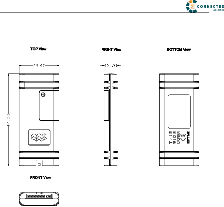
Mechanical Structure(mm)

© 2017 Connected Holdings LLC 9 / 9
FCC Statement
This equipment has been tested and found to comply with the limits for a Class B digital
device, pursuant to Part 15 of the FCC Rules. These limits are designed to provide reasonable
protection against harmful interference in a residential installation. This equipment generates
uses and can radiate radio frequency energy and, if not installed and used in accordance with
the instructions, may cause harmful interference to radio communications. However, there is
no guarantee that interference will not occur in a particular installation. If this equipment does
cause harmful interference to radio or television reception, which can be determined by
turning the equipment off and on, the user is encouraged to try to correct the interference by
one or more of the following measures:
-- Reorient or relocate the receiving antenna.
-- Increase the separation between the equipment and receiver.
-- Connect the equipment into an outlet on a circuit different from that to which the receiver is
connected.
-- Consult the dealer or an experienced radio/TV technician for help.
This device complies with part 15 of the FCC Rules. Operation is subject to the following two
conditions:
(1) This device may not cause harmful interference, and (2) this device must accept any
interference received, including interference that may cause undesired operation.
Changes or modifications not expressly approved by the party responsible for compliance
could void the user's authority to operate the equipment.
IC STATEMENT
This device complies with Industry Canada licence-exempt RSS standard(s). Operation is
subject to the following two conditions: (1) this device may not cause interference, and (2)
this device must accept any interference, including interference that may cause undesired
operation of the device.
Le présent appareil est conforme aux CNR d'Industrie Canada applicables aux appareils radio
exempts de licence. L'exploitation est autorisée aux deux conditions suivantes : (1) l'appareil
ne doit pas produire de brouillage, et (2) l'utilisateur de l'appareil doit accepter tout brouillage
radioélectrique subi, même si le brouillage est susceptible d'en compromettre le
fonctionnement.