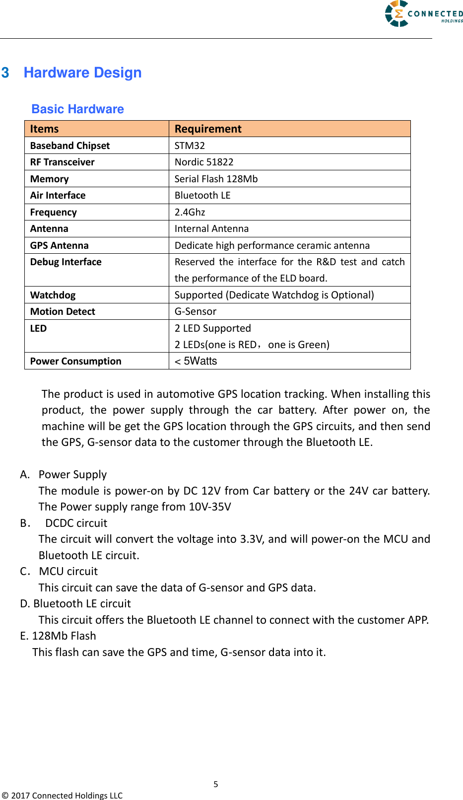
Connected XEL01 Electronic Logging Devices [ELD] Extender User Manual

Connected Holdings LLC Electronic Logging Devices [ELD] Extender

User manual

                                                                                                         1 ©  2017 Connected Holdings LLC   Electronic Logging Devices Extender for HOS   User Manual        R1.2  Contents Author Revision Changes Date Gil Winograd 1.0 Initial version 2017-04-18 Gil Winograd 1.1 Change some descriptions 2017-04-24 Gil Winograd 1.2 Change the diagram 2017-04-27         Confidential  Material:  This  document  contains  information  that  is  proprietary  and confidential, reading and copying this document is prohibited without permission.
                                                                                                         2 ©  2017 Connected Holdings LLC 1  Introduction .............................................................................................................................. 3 2  ID and Tooling Design ................................................................................................................ 4 3  Hardware Design ....................................................................................................................... 5 Basic Hardware.............................................................................................................................. 5
                                                                                                         3 ©  2017 Connected Holdings LLC 1  Introduction The ELD is a self-contained vehicle tracking device that combines GPS  location with Bluetooth LE connectivity. Logically, the device appears to a user or a server application as a single endpoint device. It can be queried, updated and configured over the Bluetooth LE connection. The ELD presents. These elements include:      Bluetooth LE connection        oad option for motion detection Application scene:      This product will be designed based on the STM32 Baseband chipset, which includes GPS functionality, Bluetooth LE, G-sensor. This baseband external connect a 128Mb serial flash. The device use one GPS antenna and a Bluetooth LE Antenna.
                                                                                                         4 ©  2017 Connected Holdings LLC 2  ID and Tooling Design The  housing  will  be  provided  by  customer.  The  product  appearance is shown as follows: Item Definition Dimension 67( L )*39( W )*14( H )mm Weight <100g
                                                                                                         5 ©  2017 Connected Holdings LLC 3  Hardware Design Basic Hardware Items Requirement Baseband Chipset STM32 RF Transceiver Nordic 51822 Memory Serial Flash 128Mb Air Interface Bluetooth LE Frequency 2.4Ghz Antenna Internal Antenna GPS Antenna Dedicate high performance ceramic antenna Debug Interface Reserved  the  interface  for  the  R&D  test  and  catch the performance of the ELD board. Watchdog Supported (Dedicate Watchdog is Optional) Motion Detect G-Sensor LED 2 LED Supported   2 LEDs(one is RED,one is Green) Power Consumption < 5Watts  The product is used in automotive GPS location tracking. When installing this product,  the  power  supply  through  the  car  battery.  After  power  on,  the machine will be get the GPS location through the GPS circuits, and then send the GPS, G-sensor data to the customer through the Bluetooth LE.  A. Power Supply The module is power-on by DC 12V from Car battery or the 24V car battery. The Power supply range from 10V-35V    B.  DCDC circuit       The circuit will convert the voltage into 3.3V, and will power-on the MCU and Bluetooth LE circuit.    C.MCU circuit       This circuit can save the data of G-sensor and GPS data. D. Bluetooth LE circuit   This circuit offers the Bluetooth LE channel to connect with the customer APP. E. 128Mb Flash This flash can save the GPS and time, G-sensor data into it.
FCC StatementThis equipment has been tested and found to comply with the limits for a Class B digital device, pursuant to Part 15 of the FCC Rules. These limits are designed to provide reasonable protection against harmful interference in a residential installation. This equipment generates uses and can radiate radio frequency energy and, if not installed and used in accordance with the instructions, may cause harmful interference to radio communications. However, there is no guarantee that interference will not occur in a particular installation. If this equipment does cause harmful interference to radio or television reception, which can be determined by turning the equipment off and on, the user is encouraged to try to correct the interference by one or more of the following measures:-- Reorient or relocate the receiving antenna.  -- Increase the separation between the equipment and receiver.   -- Connect the equipment into an outlet on a circuit different from that to which the receiver is connected.  -- Consult the dealer or an experienced radio/TV technician for help.This device complies with part 15 of the FCC Rules. Operation is subject to the following two conditions:(1) This device may not cause harmful interference, and (2) this device must accept any interference received, including interference that may cause undesired operation.Changes or modifications not expressly approved by the party responsible for compliance could void the user's authority to operate the equipment.

Navigation menu