Consilium Marine US SRT12002 12K WATT X-BAND MARINE RADAR User Manual 304202P003 Rev C
Consilium Marine US Inc. 12K WATT X-BAND MARINE RADAR 304202P003 Rev C
UserManual.wiki
>
Consilium Marine US
>
SRT12002 User Manual
>
Technical Manual 1
Contents
1.
Technical Manual 1
2.
Technical Manual 2
Technical Manual 1
Navigation menu
Upload a User Manual
Namespaces
Wiki Guide
HTML
PDF
Info
Views
User Manual
Discussion / Help
Navigation

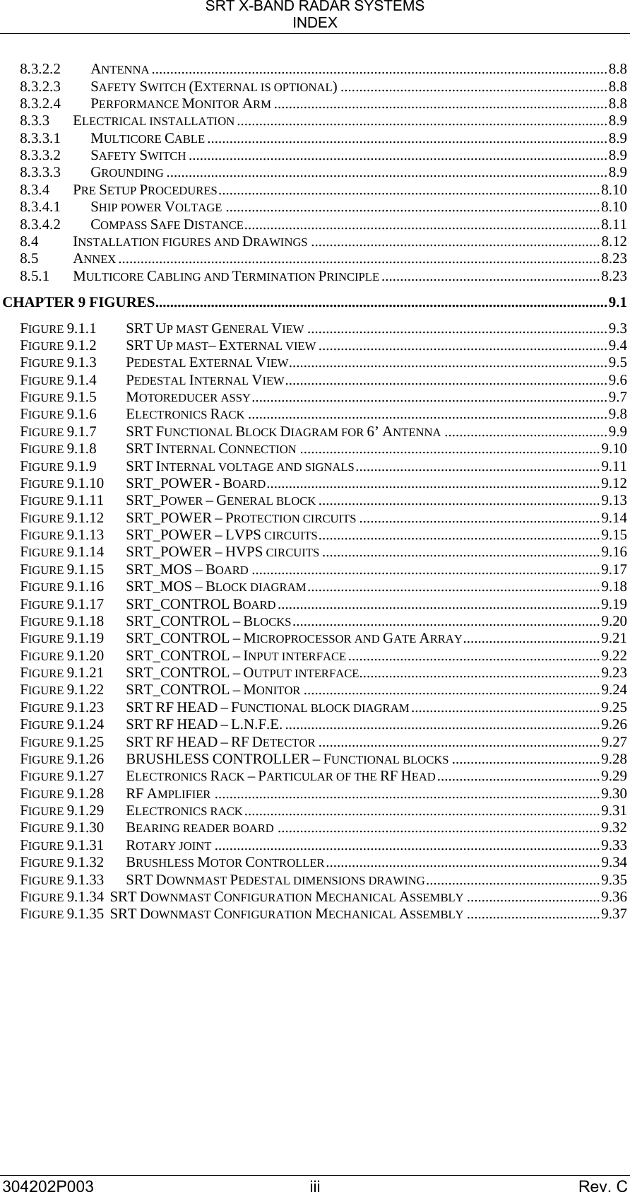
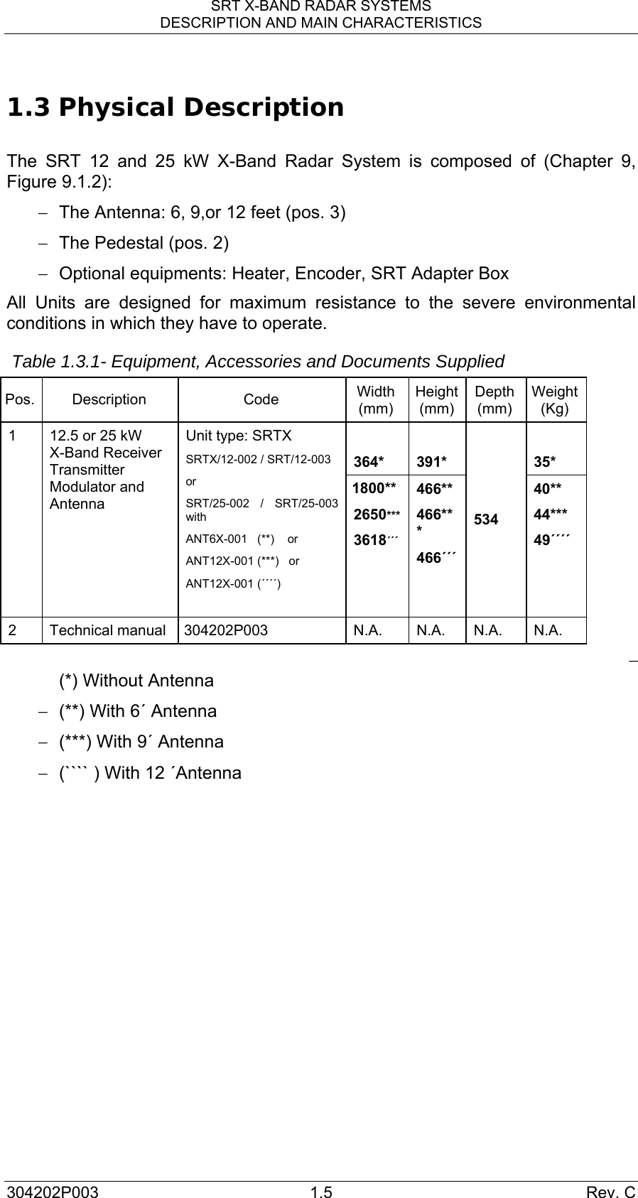
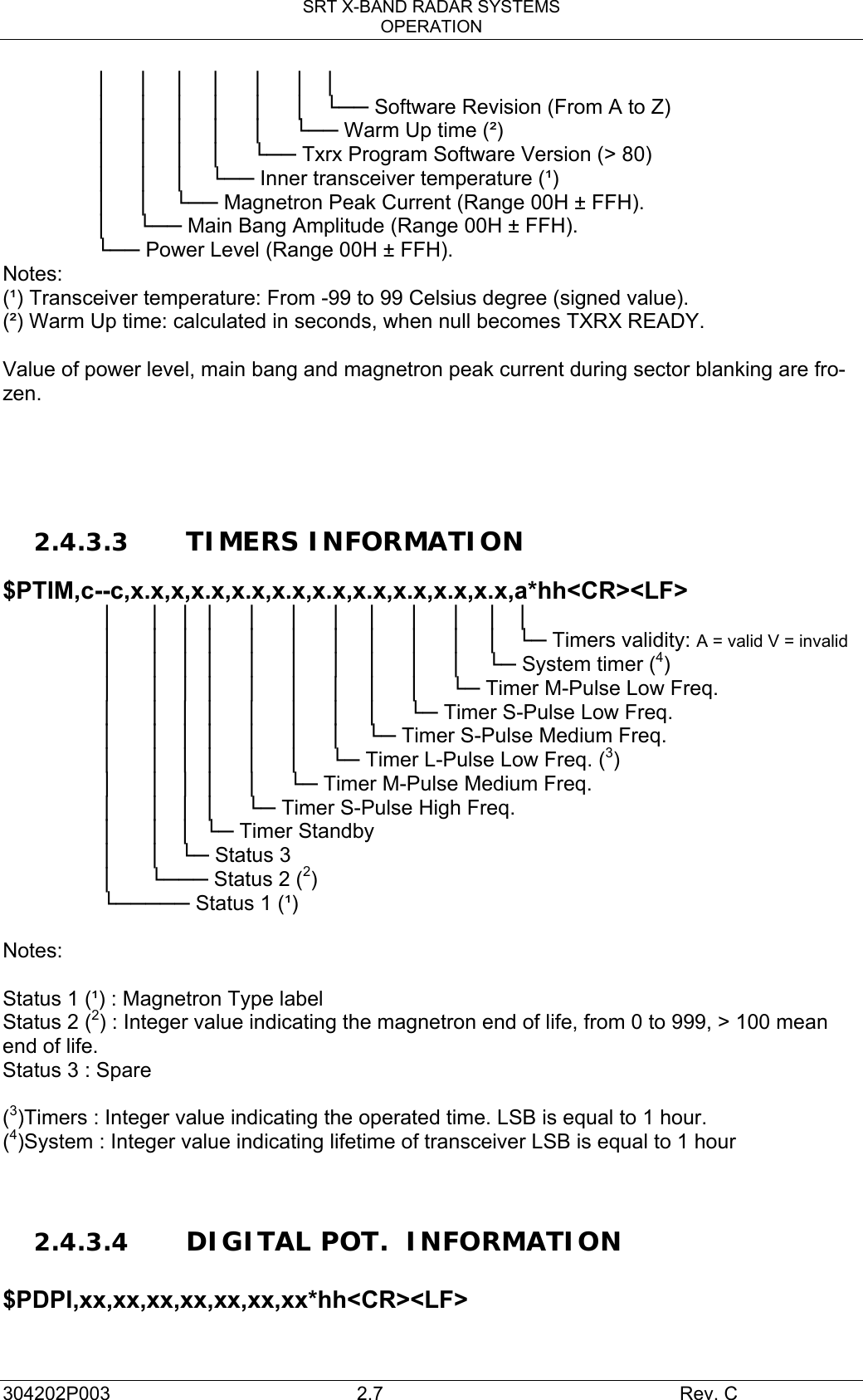
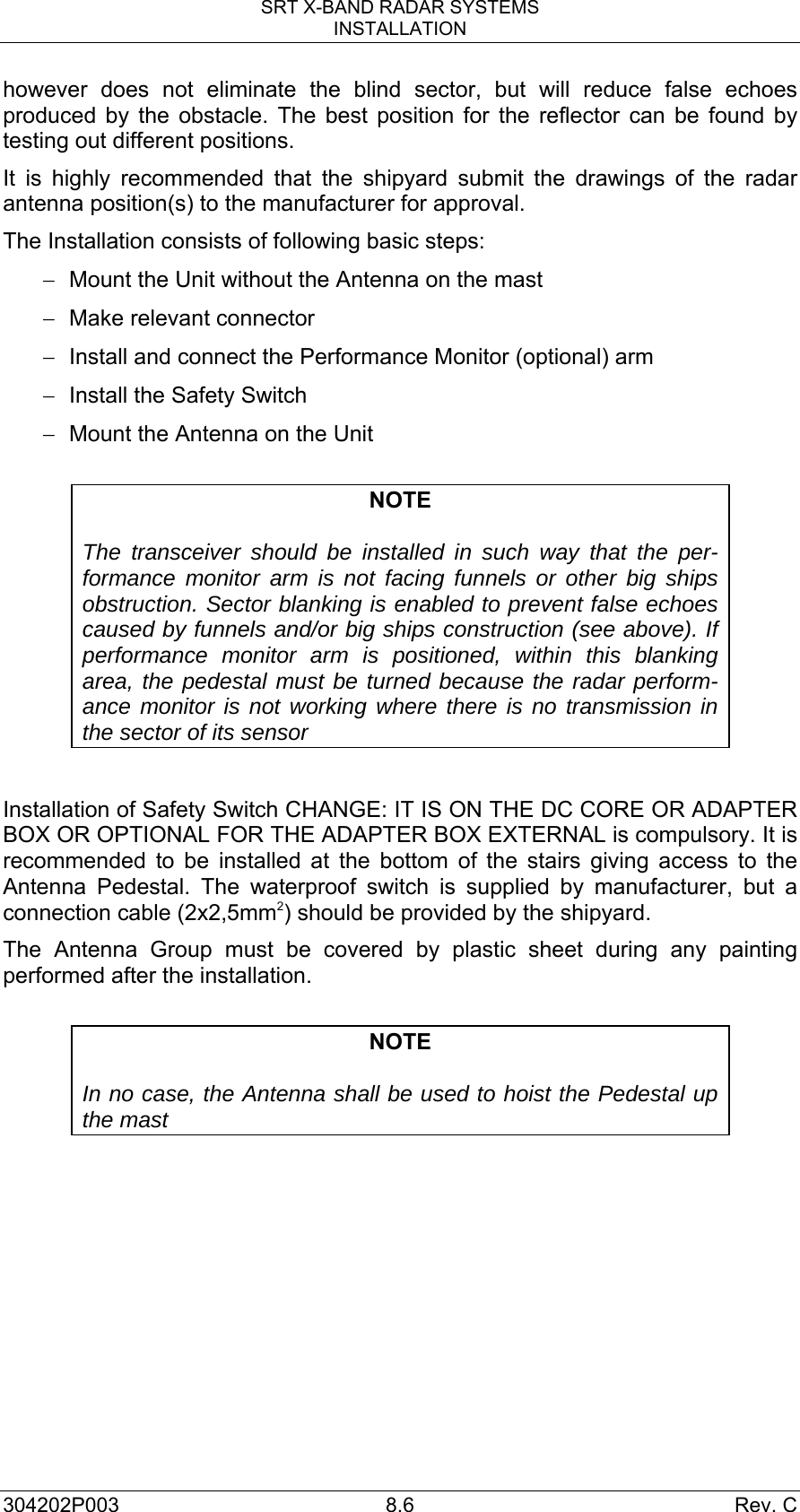
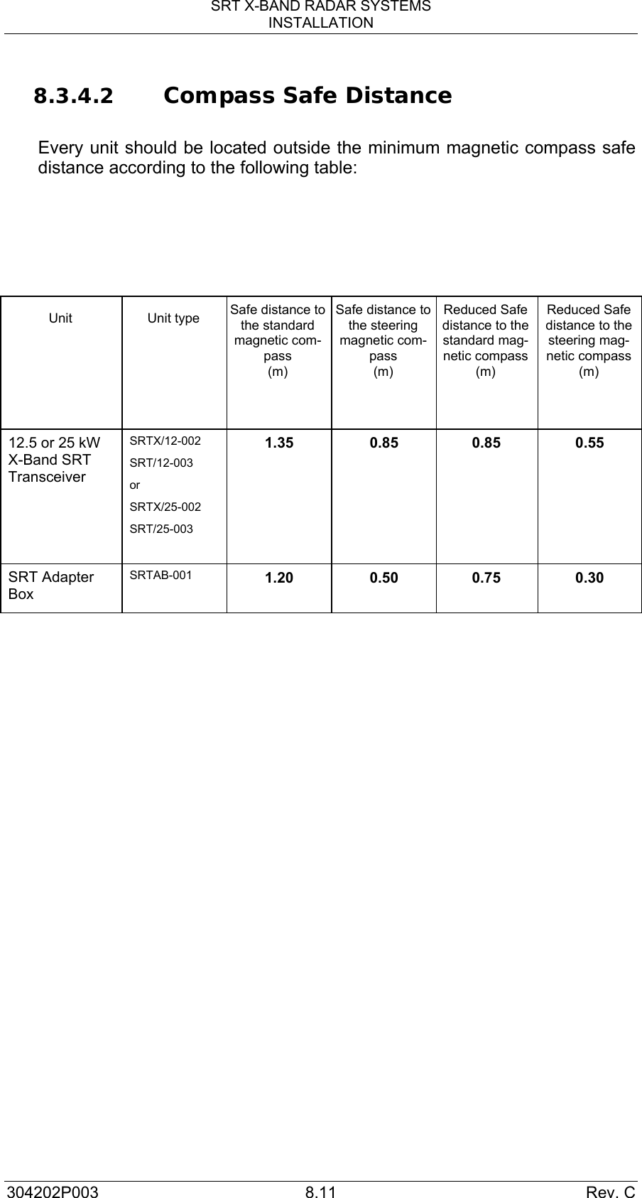
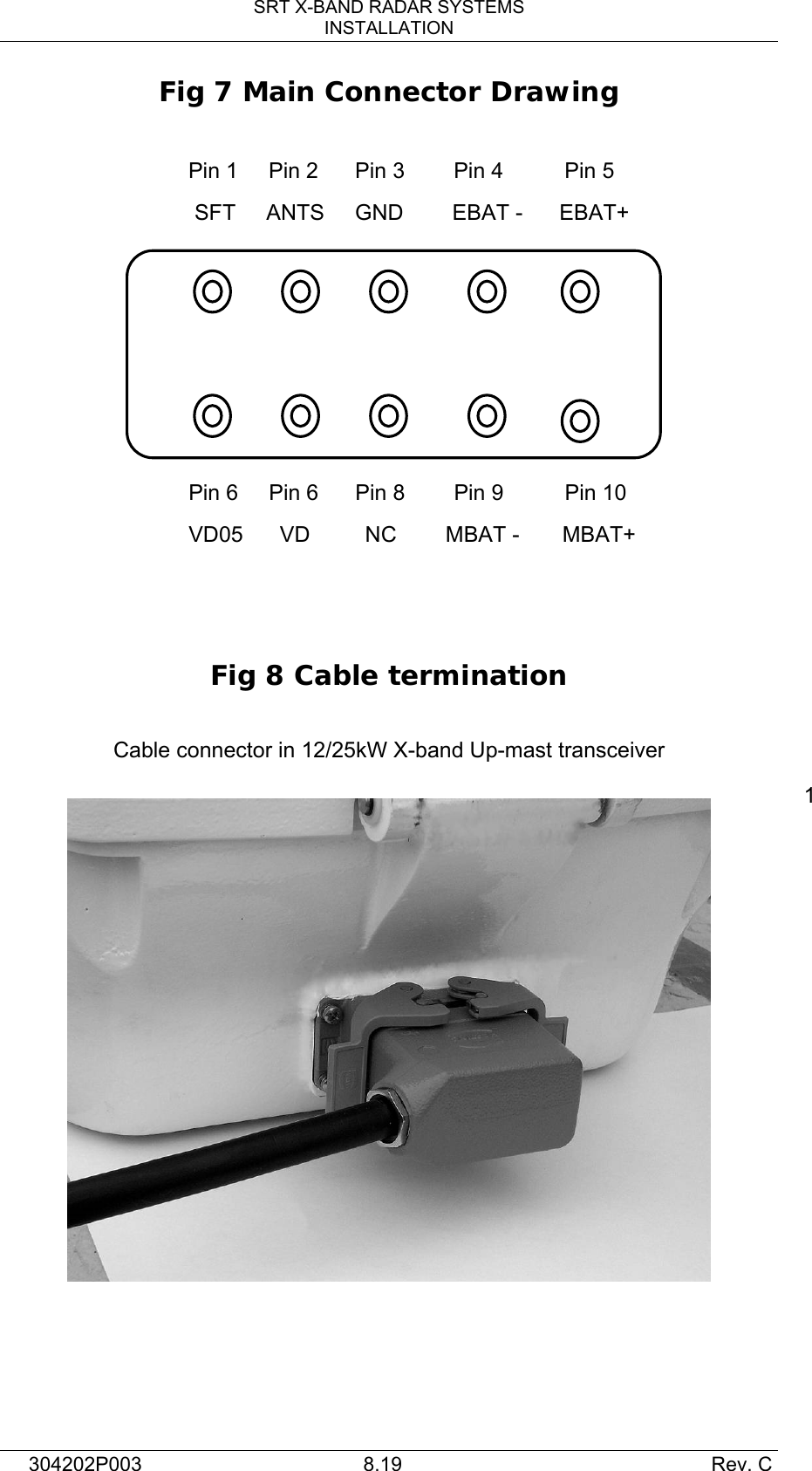
![SRT X-BAND RADAR SYSTEMS WARNINGS 304202P003 1 Rev. C WARNINGS IMPORTANT NOTE For correct operation, please, read this instruction manual carefully, before operating the equipment. HIGH VOLTAGE Radar equipment requires the use of high voltages. This can cause injury, or loss of life. Danger exists only when the units are opened, exposing internal circuits, as when servicing the equipment. You do not face any danger during normal operation. The SRT X-Band Radar System has been carefully designed to protect personnel from possible injury from high voltages at normal operation. When inspecting or servicing the equipment, nevertheless, it is recommended that the Line Switch to left open, as an added protection. Although every effort has been made to eliminate danger to personnel, no responsibility is accepted for any injury or loss of life suffered in connection with the equipment. RADIO-FREQUENCY RADIATION Harmful effects (particularly to the eyes) may be caused by exposure of any part of the human body to radio-frequency mean power densities. Hazard distances at which power densities of 100 W/ m², 50 W/ m² and 10 W/m² exist, are given in the following table Configuration Distance to 100 W/ m² point [m] Distance to 50 W/ m² point [m] Distance to 10 W/ m² point [m] 12 kW Transceiver + 6'X Band Antenna (ANT6X-001) - 0,15 0,6 12 kW Transceiver + 9'X Band Antenna (ANT9X-001) - - 0,5 12 kW Transceiver + 12'X Band Antenna (ANT12X-001) - - 0,35 25 kW Transceiver + 6'X Band Antenna (ANT6X-001) 0,1 0,2 1,3 25 kW Transceiver + 9'X Band Antenna (ANT9X-001) - 0,1 1,0 25 kW Transceiver + 12'X Band Antenna (ANT12X-001) - 0,05 0,9 Note : 12 KW transceiver: SRT/12-002 - SRT/12-003. 25 KW transceiver: SRT/25-002 - SRT/25-003 or SRT/PED-001 / SRT/PED-002 with 25KW Dowmast transceiver, The system is however designed too always disable the microwave radiation when the antenna is not rotating.](https://usermanual.wiki/Consilium-Marine-US/SRT12002.Technical-Manual-1/User-Guide-1204349-Page-20.png)