Contec DS110-APL Spread spectrum transmitter User Manual FX DS110 APL
Contec Co., Ltd. Spread spectrum transmitter FX DS110 APL
UserManual.wiki
>
Contec
>
DS110 APL User Manual
manual
Navigation menu
Upload a User Manual
Namespaces
Wiki Guide
HTML
PDF
Info
Views
User Manual
Discussion / Help
Navigation


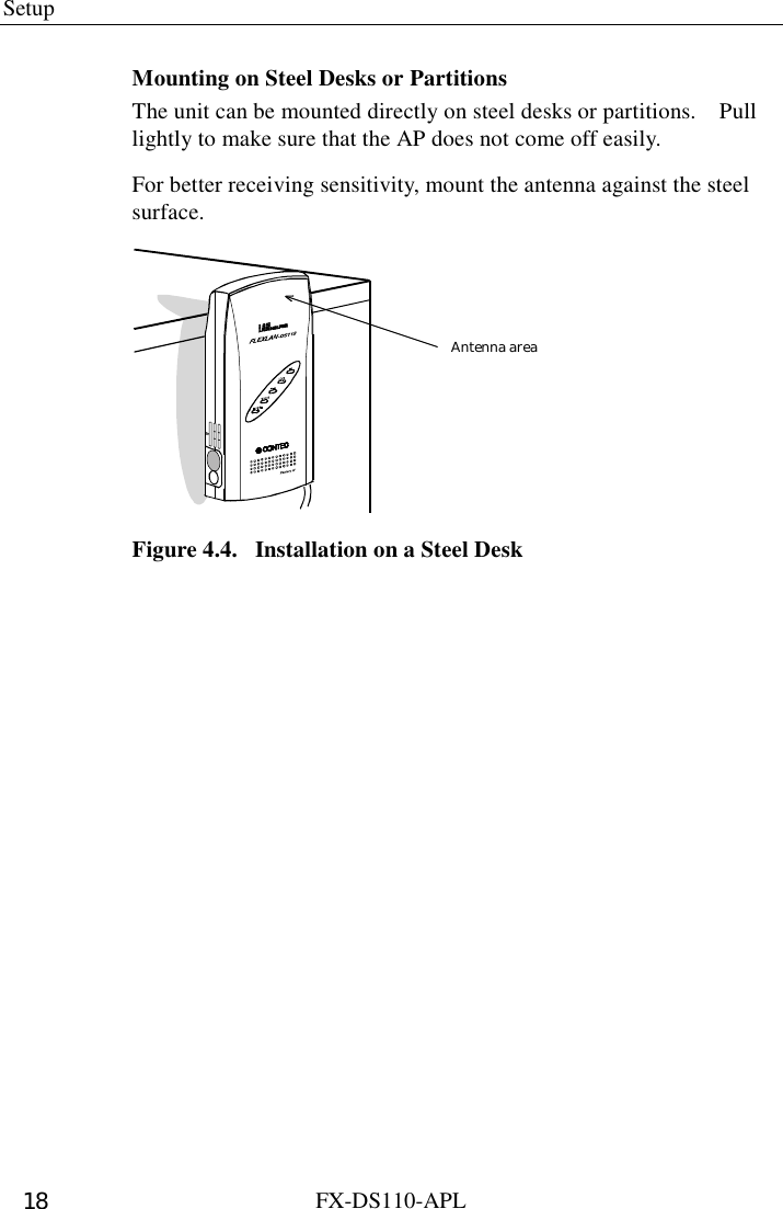
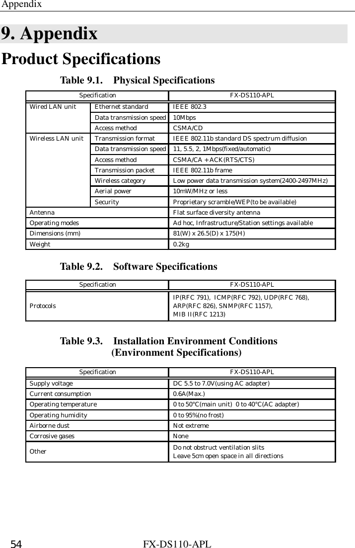
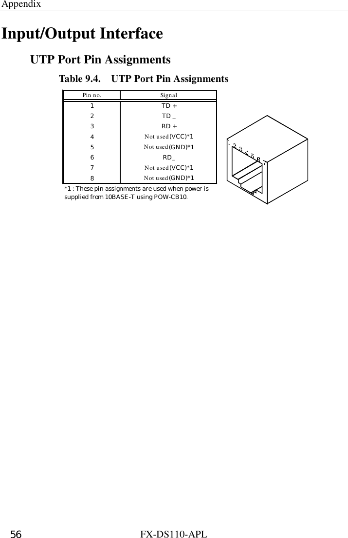
![FX-DS110-APL vii List of TablesList of TablesList of TablesList of Tables Table 2.1. ADHOC (Simple Mode) ...............................................8 Table 2.2. Infrastructure (Standard Mode) [Unit Type AP]...........8 Table 2.3. Infrastructure (Standard Mode) [Unit Type Station] ....8 Table 2.4. Other..............................................................................8 Table 2.5. DIP Switches .................................................................9 Table 3.1. Operating Modes and Communications......................15 Table 7.1. Group Names...............................................................48 Table 9.1. Physical Specifications................................................55 Table 9.2. Software Specifications...............................................55 Table 9.3. Installation Environment Conditions (Environment Specifications)...................................55 Table 9.4. UTP Port Pin Assignments..........................................57](https://usermanual.wiki/Contec/DS110-APL/User-Guide-166800-Page-7.png)


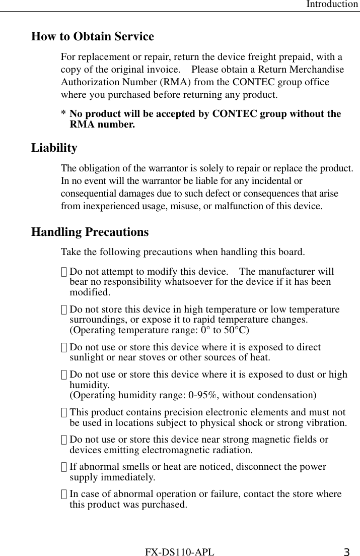

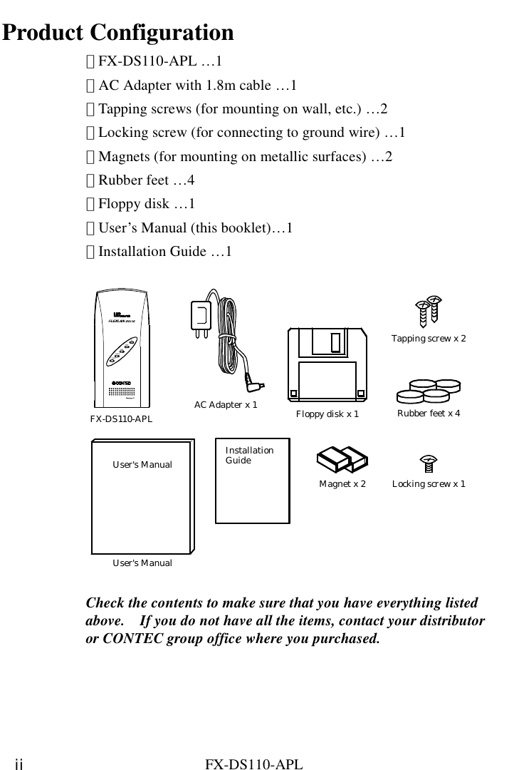
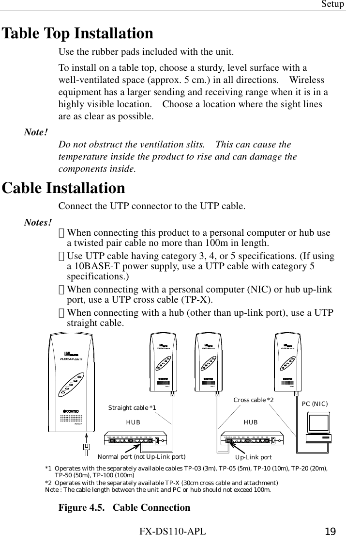
![Overview FX-DS110-APL 7 LED Indicators Table 2.1. ADHOC (Simple Mode) Flashing Startup, or startup errorOn OperatingWLINK On OperatingWRX Flashing Receiving wireless LAN dataLINK On Wire LAN connection normalRX Flashing Receiving wire LAN dataName Status IndicatorPOWER Table 2.2. Infrastructure (Standard Mode) [Unit Type AP] Flashing Startup, or startup errorOn OperatingWLINK On Wireless LAN connection normalWRX Flashing Receiving wireless LAN dataLINK On Wire LAN link connection normalRX Flashing Receiving wire LAN dataPOWERName Status Indicator Table 2.3. Infrastructure (Standard Mode) [Unit Type Station] Flashing Startup, or startup errorOn OperatingWLINK On Wireless LAN connection normalWRX Flashing Receiving wireless LAN dataLINK On Wire LAN link connection normalRX Flashing Receiving wire LAN dataPOWERName Status Indicator Table 2.4. Other Flashing 2 times Initialization errorFlashing 3 times Firmware writing errorPOWERWLINKWRXAll flashingat the same time Firmware writing in progressName Status IndicatorPOWER](https://usermanual.wiki/Contec/DS110-APL/User-Guide-166800-Page-15.png)


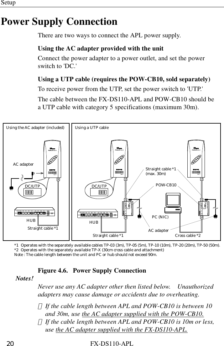

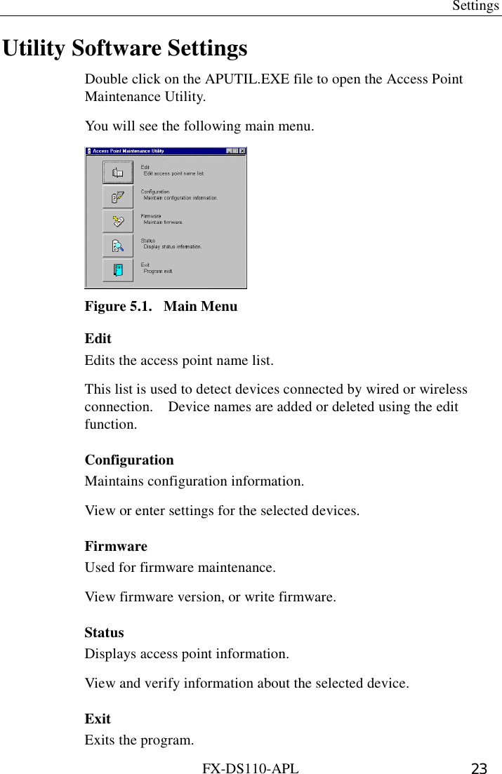
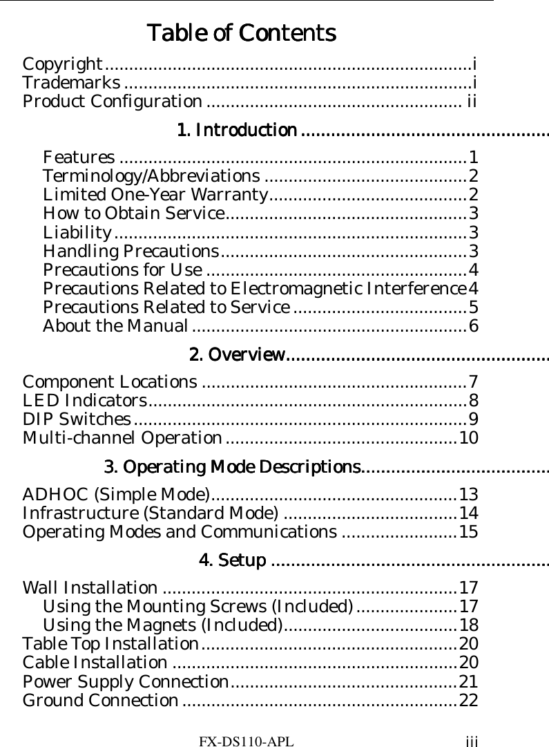
![Settings FX-DS110-APL 24 Edit Device Name On the main menu, click the [Edit] key to open the following dialog box. You can use the [Search] key to detect FX-DS110-APL devices connected in wired or wireless connections. Double click on a detected device to enter the appropriate device name. Click the [Exit] key to return to the main menu. Figure 5.2. Edit](https://usermanual.wiki/Contec/DS110-APL/User-Guide-166800-Page-32.png)
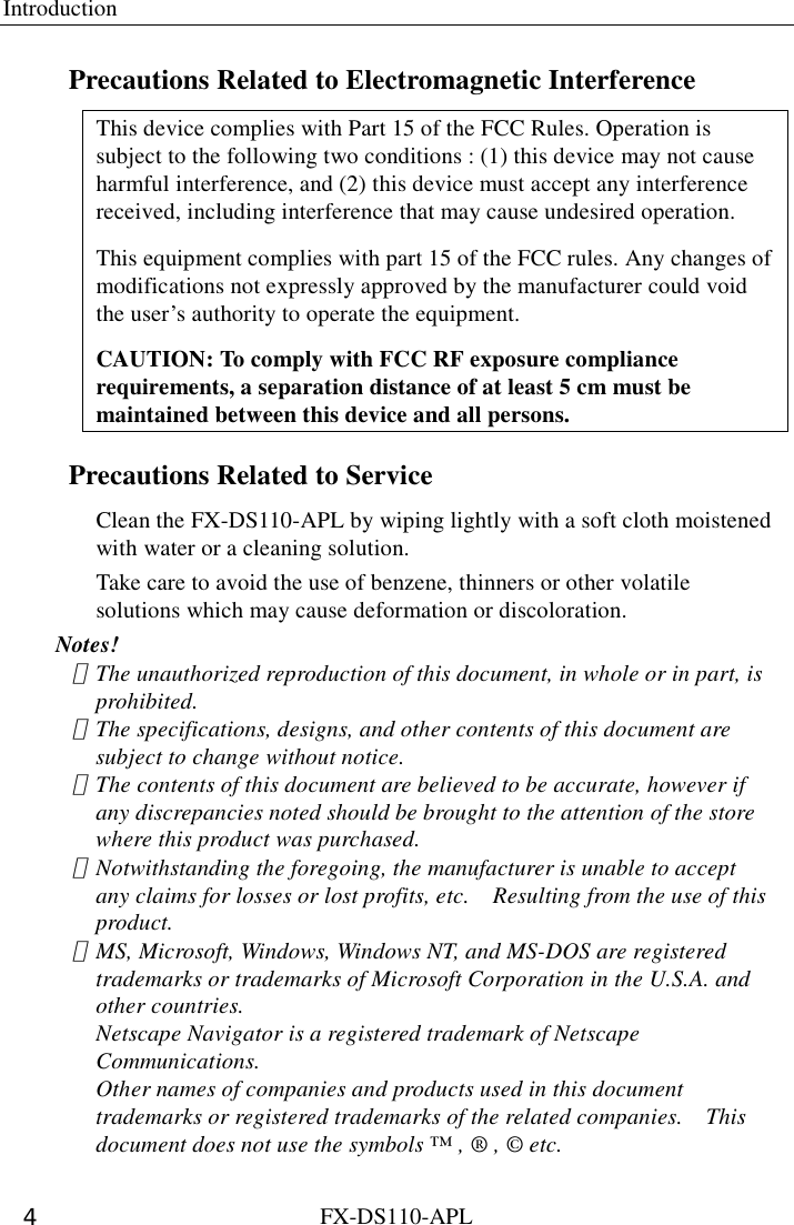
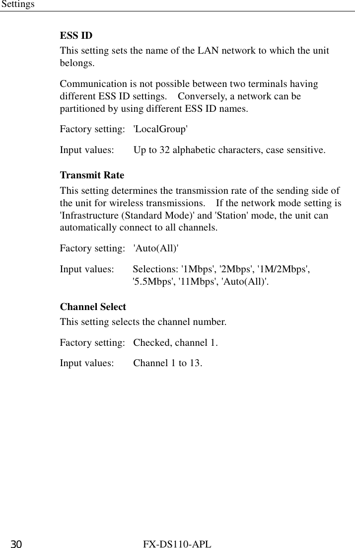
![Settings FX-DS110-APL 25 Configuration On the main menu, click the [Configuration] key to open the following dialog box. This allows you to view or enter settings for the selected device. The dialog box contains IP parameter settings including IP address, subnet mask, etc., wireless parameter settings including operating mode, unit type, ESS ID, etc., as well as SNMP and spanning tree settings. The Base tab has settings shared by all operating modes. These settings are required. The SNMP tab has settings that are needed when using SNMP agent functions. The Spanning Tree tab is valid only when the Network Mode setting is 'ADHOC (Simple Mode)' in the Base tab. Click the [Exit] key to return to the main menu. To enable the APL setting, reboot the unit. Figure 5.3. Configuration](https://usermanual.wiki/Contec/DS110-APL/User-Guide-166800-Page-33.png)
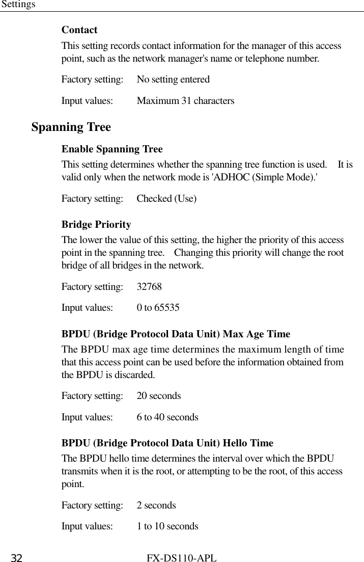
![Settings FX-DS110-APL 26 Firmware On the main menu, click the [Firmware] key to open the following dialog box. This screen lets you view firmware version information, and write firmware. Click the [Exit] key to return to the main menu. Figure 5.4. Firmware](https://usermanual.wiki/Contec/DS110-APL/User-Guide-166800-Page-34.png)
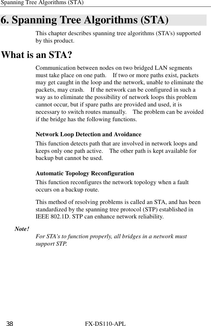
![Settings FX-DS110-APL 27 Status On the main menu, click the [Status] key to open the following dialog box. This screen lets you view status information about the FX-DS110-APL device. Click the [Exit] key to return to the main menu. Figure 5.5. Status](https://usermanual.wiki/Contec/DS110-APL/User-Guide-166800-Page-35.png)
![Settings FX-DS110-APL 28 Setting Descriptions Edit Access Point Giving a name to an access point makes it easier to identify on the network. Names may be up to 32 characters. A maximum of 1024 names may be entered. Base IP Address Enter the IP address of the home station. This is written on the seal on the bottom of each unit at the factory. This setting is not necessary to use the APL as a wireless device, but if it is used in combination with APE, or if the APL is accessed through different routers, the IP address must be entered. Factory setting: A unique value is assigned using the lower 3 bytes of the 6-byte APL Ethernet address. (Example) Ethernet address IP address [00-80-4C-01-02-03] →[10.1.2.3][00-80-4C-0D-0E-0F] →[10.13.14.15] The initial '10' is common to all settings. Subnet Mask If a subnet is used, enter the subnet mask number. Factory setting: [255.0.0.0] Default Gateway This setting determines the IP address of the network router to which this unit belongs. Factory setting: [0.0.0.0]](https://usermanual.wiki/Contec/DS110-APL/User-Guide-166800-Page-36.png)
![Settings FX-DS110-APL 29 Enable DIP Switch If this box is checked, the DIP switch settings on this unit (mode and unit type) are enabled. Factory setting: Checked (DIP switches enabled) ・ Network Mode Determines the operating mode of this unit. This setting is not available if 'Enable DIP Switch' is checked. Factory setting: Setting not available (DIP switch setting enabled). ・ Unit Type This setting determines whether the unit operates as an access point or station. In access point (AP) mode, this unit controls other user units or access points operating in station mode. In station mode, this unit is controlled by (logged in to) another AP. Factory setting: Setting not available (DIP switch setting enabled). Data Scramble This setting determines whether wireless data is scrambled. Note that it is not possible to communicate between a terminal with data scramble enabled and a terminal with data scramble disabled, or between two terminals with data scramble enabled but using different scramble keys. Factory setting: Not checked (data scramble off). ・ Scramble Key Used for scrambling of wireless data. Factory setting: [00.00.00.00.00.00.00.00.00.00] Input values: Hexadecimal values (0-9, A-F).](https://usermanual.wiki/Contec/DS110-APL/User-Guide-166800-Page-37.png)
![Settings FX-DS110-APL 31 SNMP Community Name This is an SNMP recognizable character string, which functions like a password for access to the access point from an SNMP. Programs can access the access point MIB by using this community name. Factory setting: [public] Input values: Up to 31 alphabetic characters, case sensitive. Access This setting determines the access authority for the community. The selection is between 'Read Only' access or 'Read & Write' access. Factory setting: [Read & Write] Send Trap This setting determines whether the SNMP agent system will notify the user of errors such as access right errors, or APL startup. Factory setting: Unchecked (Do not send trap). ・ IP Address: Enter the IP address of the user to which the trap is to be sent. Name This setting determines the name of this access point on the SNMP. Factory setting: No setting entered Input values: Maximum 31 characters Location This setting records the physical location of the access point, such as "8F R&D Department." Factory setting: No setting entered Input values: Maximum 31 characters](https://usermanual.wiki/Contec/DS110-APL/User-Guide-166800-Page-39.png)

![Settings FX-DS110-APL 34 Other Settings Password (Activated by the 'Password' key on the Configuration window) Changes the password setting for this AP. ・ Current password Enter the current password setting for this AP. Factory setting: No setting Input values: Up to 6 alphanumeric characters, case sensitive. ・ New password Enter the new password. Input values: Up to 6 alphanumeric characters, case sensitive. ・ Confirm password For confirmation, enter the new password again. The new password will only be established for the access point if it is correctly entered twice. The new password will be effective when the access point is restarted. Input values: Up to 6 alphanumeric characters, case sensitive. Enter Password This box is displayed to require password entry for access to the access point such as reading or writing setting values, firmware maintenance, etc. Input values: Up to 6 alphanumeric characters, case sensitive. Default ([Default] key on the Settings screen) Displays the default settings for IP address, subnet mask, and default gateway on the screen. To apply these values, use the [Write] key to write the values, then the [Reboot] key to reboot.](https://usermanual.wiki/Contec/DS110-APL/User-Guide-166800-Page-42.png)
![Settings FX-DS110-APL 35 To Register or Set Up a New Access Point (1) Start the utility software. From the main menu, select Edit, and use Search to find the desired APL. If the access point name has not been set up, the MAC address and IP address will be displayed. Assigning an access point name will make the access point easier for the network to identify. (2) From the main menu, select Configuration, then use the Base tab to enter the appropriate settings for the network environment (IP address, network mode, data scramble, ESS ID, transmit rate, channel). Also, enter any necessary settings on the SNMP and Spanning Tree tabs. *Note that the spanning tree can only be used when the network mode is ADHOC' mode. (3) When the settings are complete, select [Write]. The settings will be valid when the device is rebooted. To Edit Settings for an Existing Access Point (1) Start the utility software. From the main menu, select Configuration, and then select the access point you wish to edit from the access point name list. *Once an APL on the network has been located using Search, its settings are stored in a file. It is not necessary to use Search each time the utility software is started. (2) Edit the settings as desired. (3) When the settings are complete, select [Write]. The settings will be valid when the device is rebooted.](https://usermanual.wiki/Contec/DS110-APL/User-Guide-166800-Page-43.png)
![Settings FX-DS110-APL 36 To Use Data scramble Functions for Better Security (1) Start the utility software. From the main menu, select Configuration, and then select the access point you wish to edit from the access point name list. *Once an APL on the network has been located using Search, its settings are stored in a file. It is not necessary to use Search each time the utility software is started. (2) On the Base tab, use the Data Scramble checkbox and set the scramble key. (3) When the settings are complete, select [Write]. The settings will be valid when the device is rebooted. To Use SNMP Agent Functions (1) Start the utility software. From the main menu, select Configuration, and then select the access point you wish to edit from the access point name list. *Once an APL on the network has been located using Search, its settings are stored in a file. It is not necessary to use Search each time the utility software is started. (2) On the SNMP tab, make the necessary settings (Community Name, Access, Send Trap, Name, Location, Contact). (3) When the settings are complete, select [Write]. The settings will be valid when the device is rebooted.](https://usermanual.wiki/Contec/DS110-APL/User-Guide-166800-Page-44.png)
![Settings FX-DS110-APL 37 To Use Spanning Tree Spanning tree is enabled when the APL operating mode is ADHOC mode. (1) Start the utility software. From the main menu, select Configuration, and then select the access point you wish to edit from the access point name list. *Once an APL on the network has been located using Search, its settings are stored in a file. It is not necessary to use Search each time the utility software is started. (2) On the Base tab, set the network mode to 'AOHOC(Simple Mode).' Or use the DIP switch setting to select ADHOC. Then make the necessary settings on the Spanning Tree tab. *Note that all settings other than check boxes may be left at their factory settings. (3) When the settings are complete, select [Write]. The settings will be valid when the device is rebooted. To Access the APL from a Different Router This requires setting the IP parameters on the Base tab (IP Address, Subnet Mask, Default Gateway). This is also necessary when configuring a network using the FX-DS110-APE. (1) Start the utility software. From the main menu, select Configuration, and then select the access point you wish to edit from the access point name list. *Once an APL on the network has been located using Search, its settings are stored in a file. It is not necessary to use Search each time the utility software is started. (2) On the Base tab, set the IP parameters (IP Address, Subnet Mask, Default Gateway). (3) When the settings are complete, select [Write]. The settings will be valid when the device is rebooted.](https://usermanual.wiki/Contec/DS110-APL/User-Guide-166800-Page-45.png)


![SNMP Agent Functions FX-DS110-APL 49 Building-in to SNMPc Follow these steps to install SNMPc Ver. 4. (1) Start the SNMPc Setup.program. To start SNMPc Ver. 4, select [Start] – [SNMPc 4.0] – [Setup]. After startup, verify the user registration information. (2) Insert the Maintenance Tools floppy disk provided with this product into the floppy disk drive. Enter the floppy disk drive path name followed by SNMPc.4\, and click 'OK.' Example: If the floppy disk drive is the A: drive, enter A:\SNMPc.4\. (3) Select [CONTEC FX-DS110-APL], and click [OK] to start installation. (4) When the following message appears, click [No] to exit the program. [Do you want to install additional vendors?] MIB Database Updates After installing a new vendor, you will have to update the MIB database the next time SNMPc is started. Follow these steps to update the MIB database. In this description we use 'SNMPc Ver.4' as an example. (1) Start SNMPc. To start SNMPc Ver. 4, select [Start] – [SNMPc 4.0] – [SNMPc]. (2) Click [Yes] to update the MIB database. (3) When you are finished updating the MIB database, click [OK]. The build-in to SNMPc is not complete.](https://usermanual.wiki/Contec/DS110-APL/User-Guide-166800-Page-57.png)


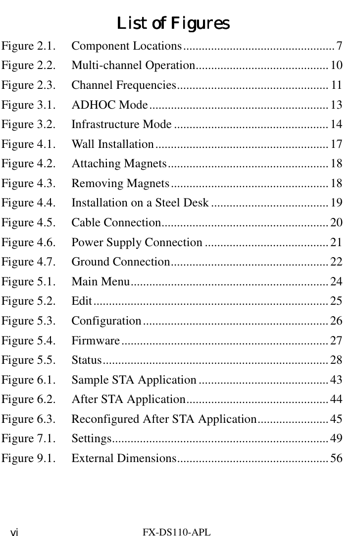
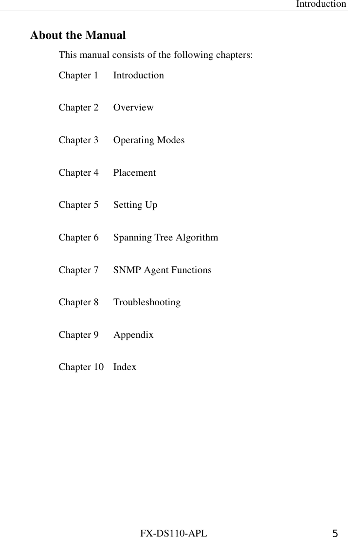
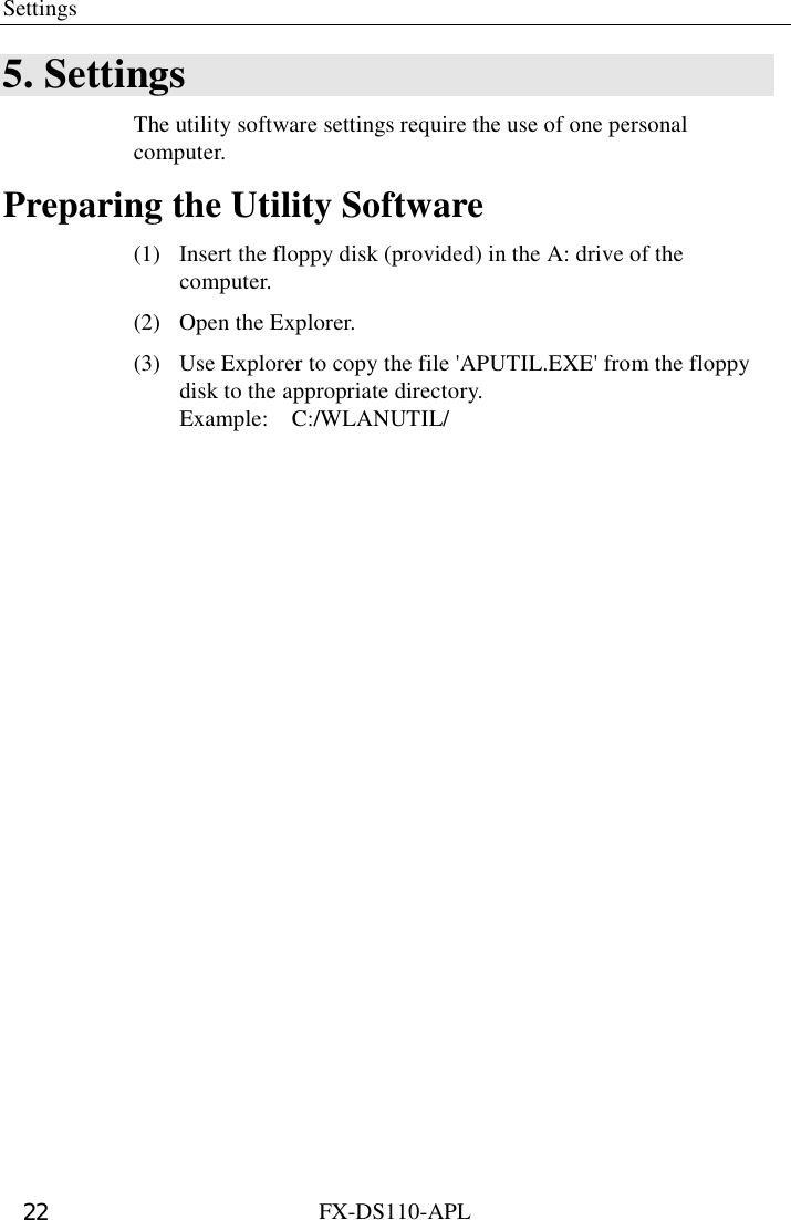
![Appendix FX-DS110-APL 55 DC/UTP UTPPOWERWRXWLINKLINKRX8117526.5[mm] Figure 9.1. External Dimensions](https://usermanual.wiki/Contec/DS110-APL/User-Guide-166800-Page-63.png)

![A-46-500 LZV6181 [010509]](https://usermanual.wiki/Contec/DS110-APL/User-Guide-166800-Page-69.png)