Contec DS540-APDL Wireless LAN Access Point User Manual A 46 824Cover
Contec Co., Ltd. Wireless LAN Access Point A 46 824Cover
UserManual.wiki
>
Contec
>
DS540-APDL User Manual
>
Manual
Contents
1.
Manual
2.
FCC notices
3.
FCC Statements
Manual
Navigation menu
Upload a User Manual
Namespaces
Wiki Guide
HTML
PDF
Info
Views
User Manual
Discussion / Help
Navigation


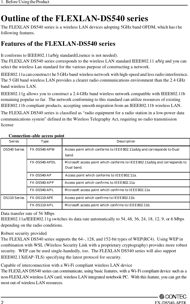
![1. Before Using the Product FX-DS540-APDL 1 1. Before Using the Product This chapter provides information you should know before using the FX-DS540-APDL. About the FX-DS540-APDL The FX-DS540-APDL is a wireless LAN Access point. It conforms to the wireless LAN standard specification IEEE802.11a/IEEE802.11b/IEEE802.11g. The FX-DS540-APDL operates in the 5 or 2.4-GHz radio frequency band. The FX-D540-APDL enables high-speed communication at up to 54 Mbps and is suitable for constructing 54 Mbs wireless LAN when used in combination with the Contec user unit [FX-DS540-PCD, FX-DS540-PCC, FX-DS540-PCC2] confirmed to IEEE802.11a or [FX-DS110-PCC, FX-DS110-PCC2] confirmed to IEEE802.11b. While inheriting the proprietary functions highly evaluated mainly by corporate users, such as those for IP tunneling and roaming, the FX-D540-APDL supports data rates of up to 54 Mbps and the 64-, 128-, and 152-bit versions of WEP to provide higher security. It also supports WSL (proprietary encryption), IEEE802.1X (EAP -TLS), ESS ID concealing, and ANY ID rejection as well. Be sure to read it carefully so that you can use the product correctly. The FLEXLAN DS540 series employs a wireless LAN chip manufactured by Atheros Communications Inc. The main board, firmware, and enhancements are developed by CONTEC based on its abundant experience and technical skills in LAN. Features - It conforms to IEEE802.11a/b/g standard IEEE802.11a/IEEE802.11b/IEEE802.11g and you can select the wireless Lan standard for the various purpose of constructing a network. Capable of effectively using existing wireless network resources. - Compact housing with internal antenna (for diversity), saving space for installation. - A single unit of FX-DS540-AP DL accepts log-in from up to 254 stations. - Easy configuration and management using a WWW browser. Assorted maintenance methods are available to different systems and applications, including FTP commands, TELNET. - IP tunneling feature integrated, enabling communication even at a roaming destination beyond the router without making any changes to network configuration. - Various securities -- MAC address filtering, IEEE802.1X, ESS ID concealing and ANY ID rejection as well as WEP(64, 128, 152bit) – integrated, enabling to provide the robust security. - SNMP agent feature integrated, enabling network management using SNMP supported network management software (such as CONTEC SNMPc). MIBII and private MIB are supported. - The FX-DS540-APDL can be powered via a network cable when using the power supply unit POW -CB20 or POW -CBM4.](https://usermanual.wiki/Contec/DS540-APDL.Manual/User-Guide-461972-Page-8.png)


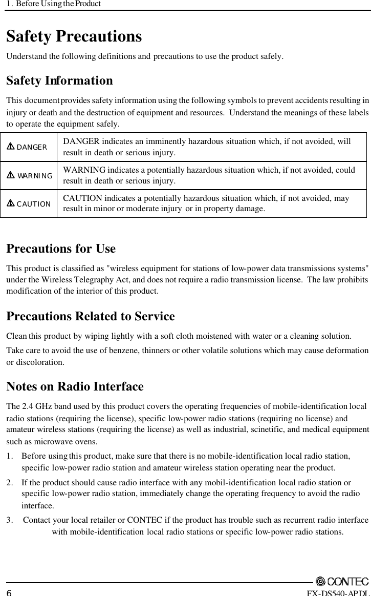


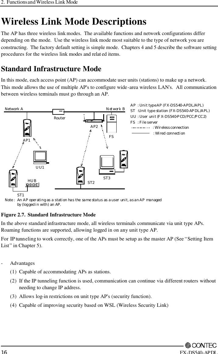


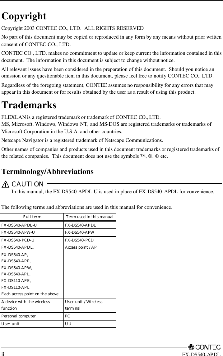
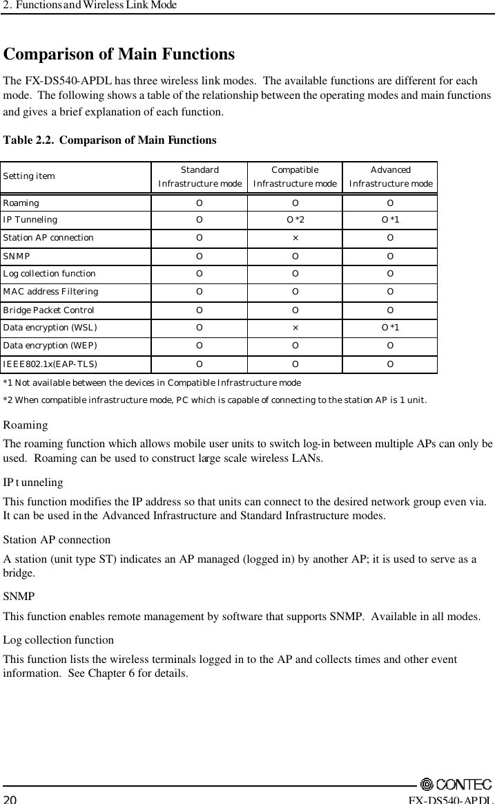
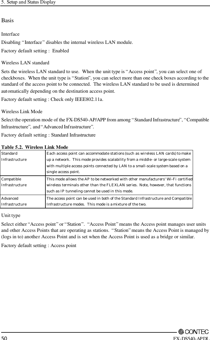
![2. Functions and Wireless Link Mode FX-DS540-APDL 19 Wireless Link Mode and Communications The table below shows which wireless terminals can communicate with each other depending on the operating mode of the AP and user unit. [Table notation and notes] 1. UU stands for “user unit ”. 2. AP⇔UU indicates communications between a unit type AP and user unit. 3. ST indicates an “AP managed by (logged in to) another AP ” which operates in the same way as a user unit. See Chapter 5 for details of the setup procedure. Table 2.1. Wireless Link Mode and Communications Terminal able to communicate AP Wireless Link Mode AP⇔UU AP⇔ST Standard Infrastructure O O Compatible Infrastructure O × Advanced Infrastructure O O](https://usermanual.wiki/Contec/DS540-APDL.Manual/User-Guide-461972-Page-26.png)


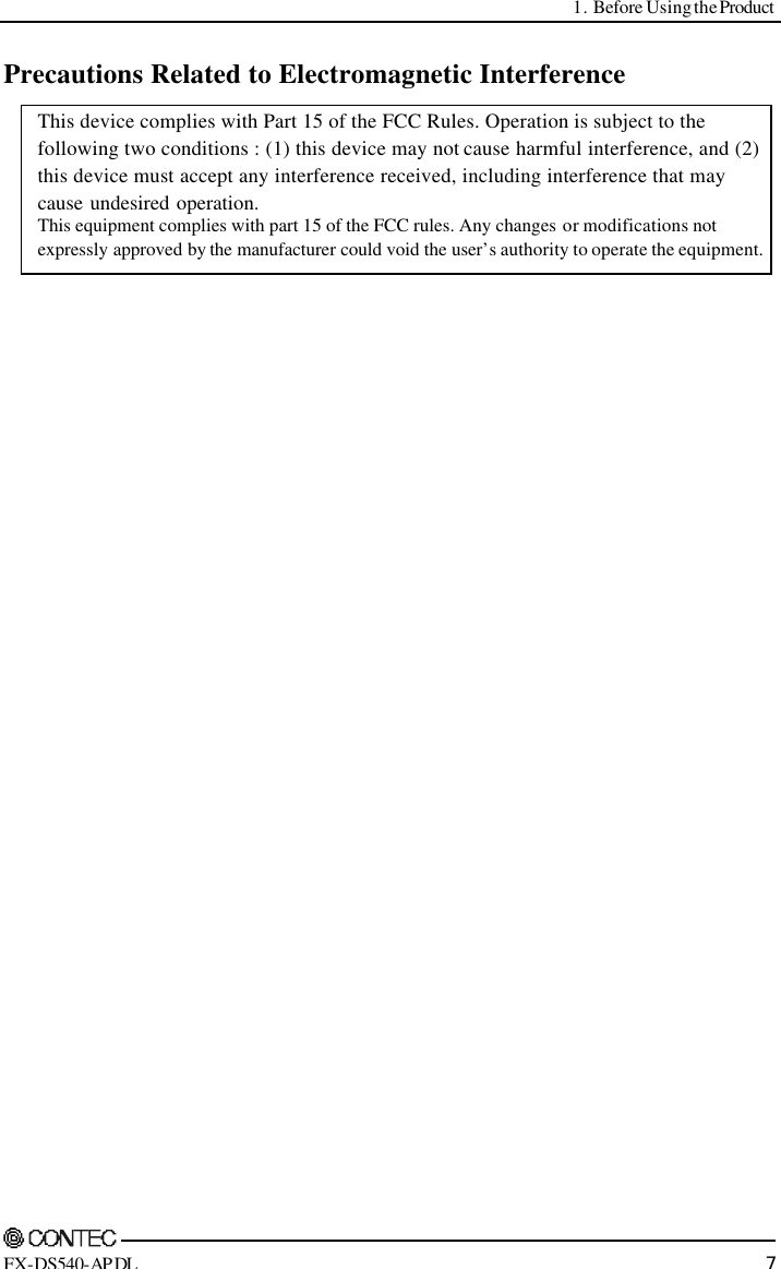
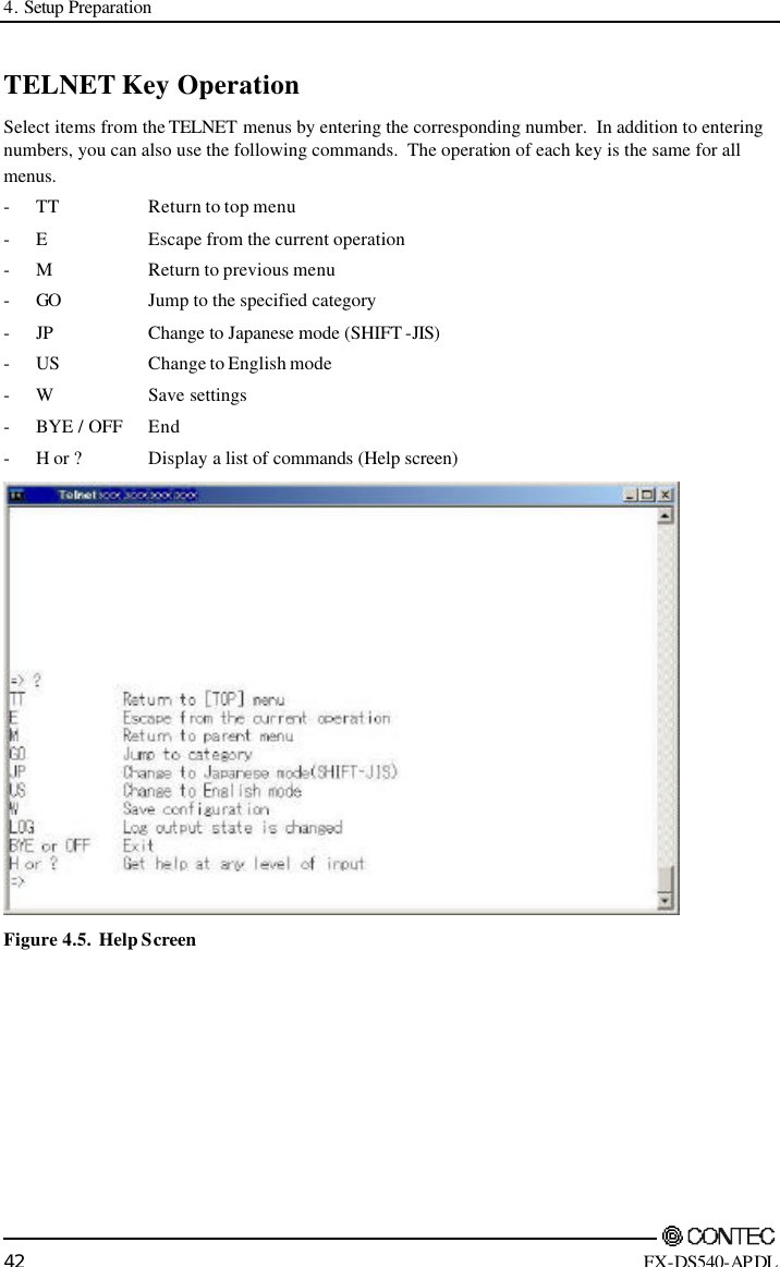
![4. Setup Preparation FX-DS540-APDL 39 Connecting to the Web Browser PC When using a web browser to setup the AP, you can connect via either a LAN or a modem. Use the following procedure to connect the web browser. Connecting via a LAN (1) Connect the PC on which you will run the web browser to the same network as the AP. Alternatively, you can use a UTP cable to connect the PC directly to the AP. In that case, use a crossed-cable. The connection will not work if you use a standard straight-through cable. CAUTION You may not be able to establish a connection if the web browser is setup to use a proxy. In this case, change the setting to not use a proxy. Remember to change the proxy setting back when you have finished setting up the AP. Connecting to an FX-DS540-APDL To connect the web browser to the AP, the IP address of the PC on which you run the web browser must be in the same network group as the IP address of the AP. The factory default IP address set in the AP is always in the class A network group starting with [10] (that is, 10.xxx.xxx.xxx). Accordingly, set the IP address of the PC to also start with [10] ([IP 10.1.1.1, MASK 255.0.0.0], for example). Remember to set the IP address of the PC back to its previous value after you have finished with the connection for setting up the AP. You can also change and set the AP ’s IP address according to the PC being used for setup. (1) Start the web browser Recommended web browsers are Microsoft Internet Explorer 5.01 or later and Netscape Navigator 6.0 or later. (2) After starting the web browser, enter the IP address of the AP in the URL field. For example, if the IP address of the AP is [10.66.1.1], enter the following: http://10.66.1.1 / Refer to Chapter 5 below as you perform software setup. (3) When connecting it to the product, input screen of the password is displayed. Enter the password. No password has been set by factory default. When you log in at first, not input anything in the form and then click the “Log-in ” button to log in. (4) Click on [Setup] in the Top Menu and open the Setup submenu. Choose and click on the desired item in the submenu to open its setup dialog box. (5) After changing the setting of each item, press the [Send] button on the page to send the new setting to the AP. The setting sent to the AP is temporarily retained in the AP. To save temporary data retained in the AP, click on the [Save] button on the left menu or top page, then choose “Yes” in the confirmation dialog box. For the saved settings to take effect, click on the [Restart] button and choose “Yes” in the confirmation dialog box to restart the AP. To save settings and restart the AP at the same time, click on the [Save/Restart] button and choose “Yes” in the confirmation dialog box. For details of setup or Confirmation of status, refer to Chapter 5 to set up software.](https://usermanual.wiki/Contec/DS540-APDL.Manual/User-Guide-461972-Page-46.png)
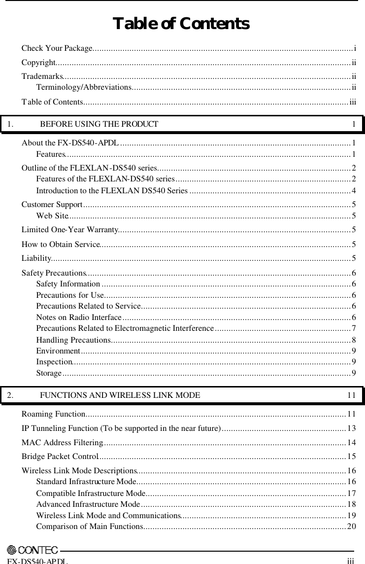
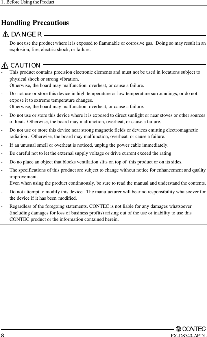
![4. Setup Preparation 40 FX-DS540-APDL Setup Using TELNET Run Telnet on a PC connected within the same LAN to set up this product. As Telnet is a text based program, it requires a bit complicated setup operations but it can be used for setup even on an old PC with a browser which does not support setup through a web browser. Figure 4.2. Example of TELNET Setting Screen Connecting to an FX-DS540-APDL For connecting the PC for setup to the AP using TELNET, the PC’s IP address and the AP’s IP address must belong to the same network group. The IP address factory-set for the AP belongs to the class-A network group beginning with 10, such as 10.xxx.xxx.xxx. For the PC to be used for setup, therefore, assign an IP address beginning with 10 (for example, [IP 10.1.1.1, MASK 255.0.0.0]). After connecting the PC to the AP and setting it up, restore the original IP address of the PC. The IP address of the AP should be changed when it is set up. You can also change and setup the IP address of AP depending on PC to set. (1) Bring up the command prompt. In Windows 98 or Windows ME, choose “MS-DOS Prompt” from “Programs” in the Start Menu. In Windows 2000 or Windows XP, choose “Command Prompt” from “Programs” in the Start Menu. (2) Connect it by using TELNET and then connect it to AP by using telnet command. For example, if the IP address of the AP is [10.66.1.1], enter the following: telnet 10.66.1.1](https://usermanual.wiki/Contec/DS540-APDL.Manual/User-Guide-461972-Page-47.png)
![4. Setup Preparation FX-DS540-APDL 41 (3) Enter the password at the [Password:] prompt. The default factory setting is no password. To login, just press the Enter key without entering anything. Figure 4.3. Password entry screen (4) When password is entered correctly, TOP menu is displayed. Figure 4.4. TOP menu CAUTION The console program uses the “Shift-JIS” character set for Kanji codes. If characters do not display correctly, check the Kanji code setting for the terminal.](https://usermanual.wiki/Contec/DS540-APDL.Manual/User-Guide-461972-Page-48.png)
![4. Setup Preparation 44 FX-DS540-APDL Setting the IP address (1) Select [2. Setup]. Figure 4.6. IP Address Setting Screen (2) Select [3. IP Address] and enter the IP address assigned to the AP on the wired LAN. (3) Select [4. Sub-Net Mask] and enter the sub-net mask for the IP address set in step 2. (4) Select [5. Default Gateway] and enter the IP address of the default gateway. You do not need to enter an IP address if there is no default gateway. (5) Press the [W] key or return to the top menu and select [3. Writing] to save the settings, then enter [BYE] or return to the top menu and select [1. Exit] to disconnect the terminal. After restarting the AP, setting is enable. This completes network setup. You can now use a web browser for setup and perform network management using SNMP.](https://usermanual.wiki/Contec/DS540-APDL.Manual/User-Guide-461972-Page-51.png)

![5. Setup and Status Display FX-DS540-APDL 49 IP address of the master AP When the master AP exists, specify the IP address of the AP that serves as the master AP. Factory default setting : 0.0.0.0 IP address of the backup AP When a backup AP exists, specify its IP address. Factory default setting : 0.0.0.0 Language setting Select the language displayed by the terminal or browser from “English” or “Japanese. Factory default setting : English Password Set a password. Enter a string of up to 31 single-byte alphanumeric characters. The password is case sensitive. At the password input prompt when starting software setup, you can log in by clicking on the [Setting] button with no password entry. If you forget your password, initialize the AP using the DIP switch (INIT). The password is cleared when the AP is initialized. Note, however, that initializing the AP resets all of its settings to their factory defaults, requiring you to make settings over again. For using the DIP switches, see Chapter 3. Factory default setting : (Not input) Ethernet Port speed Select the port speed setting. Select one of “Auto”, “100M Full Duplex”, “100M half Duplex”, “10M Full Duplex”, or “10M half Duplex”. Factory default setting : Auto Link down sense Enabling “link down sense” stops the wireless capabilities when the wired link of the access point is disconnected. Factory default setting : Disable Wireless LAN To change the wireless LAN standard (IEEE802.11a/802.11b/802.11g), wireless connection mode, and unit type, take three steps of “Basic” -> “Details” -> “Security” to make their respective settings. For any other item, you can change the setting on under “Details” or “Security”.](https://usermanual.wiki/Contec/DS540-APDL.Manual/User-Guide-461972-Page-56.png)
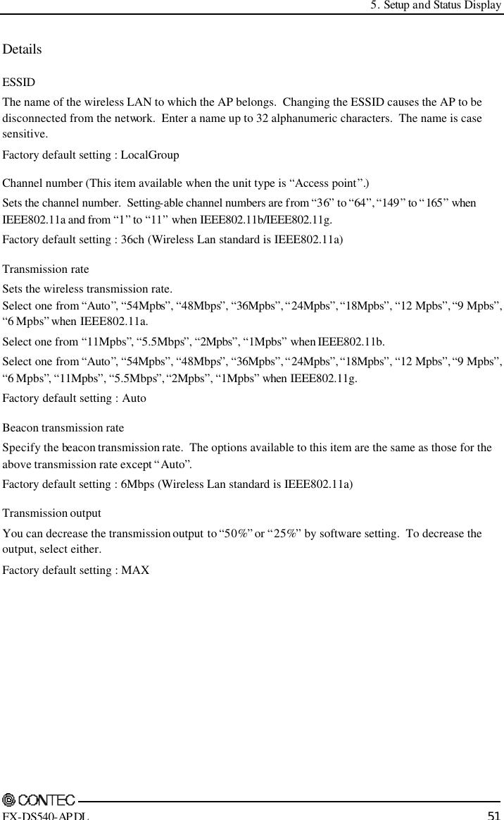


![5. Setup and Status Display 58 FX-DS540-APDL Log function The FX-DS540-APDL can preserve log information. See Chapter 6 for details of the logged data and data collection methods. Log function This specifies whether or not to enable logging. The collected log data (2048 at Max.) is stored in internal memory. Factory default setting : Disable Overwrite setting This specifies whether or not to overwrite old data when the number of log entries reaches the maximum. If disabled, log collection halts when the maximum number of entries is reached. Factory default setting : Enable Start time setting This specifies whether or not to set a logging start time. If enabled, set the time at which to start logging. Factory default setting : Beginning date set function …Disable Beginning date …0 :00 1 Jan. 2002 Detailed setting You can select the types of events to be logged. Setting [Log in], [Log Out ], [Log in refusal], [Roaming], [IP tunnel start / exit] and [Application log in / log out] to “ON” allows the selected events to be logged. Setting them to “OFF” prevents them from being logged. Factory default setting : All of the events are set to “ON” Table 5.3. Events to Be Logged Event Introduction Start Indicates that the AP has been activated. Link Up Indicates that the wired link has been connected and the link speed. Link Down Indicates that the wired link has been disconnected. Login Indicates the MAC address of the wireless terminal connected to the AP. Logout Indicates the MAC address of the wireless terminal disconnected from the AP. Login NG Indicates that the filter function rejected an attempt to log in by an unregistered wireless terminal. Roaming Indicates the MAC address of the wireless terminal roaming into the AP. Tunnel Start Indicates the MAC address of the wireless terminal that has started IP tunneling. Tunnel Stop Indicates the MAC address of the wireless terminal that has terminated IP tunneling. Application Login Indicate the IP address of the terminal that has used an application (such as telenet or FTP). Application Logout Indicates the termination of an application and the IP address of the terminal that used the application. Write Firmware Indicates that firmware has been reprogrammed. (Example: Update from Ver1.15 to Ver1.20) Write Config Indicates that the Config file has been edited. Manual Reset Indicates that the AP has been restarted by the terminal or browser.](https://usermanual.wiki/Contec/DS540-APDL.Manual/User-Guide-461972-Page-65.png)


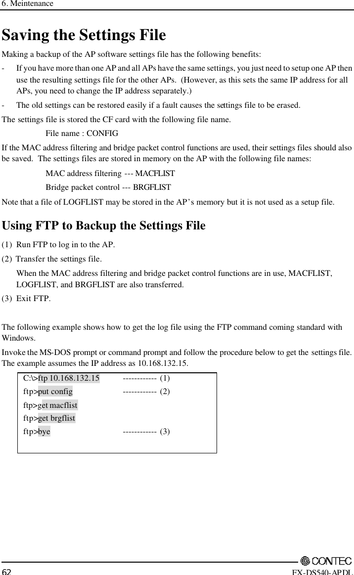
![6. Meintenance 64 FX-DS540-APDL Upgrading the Firmware The AP firmware may be upgraded to resolve any bugs found in the software or to add new functions. Contact CONTEC via our web site for details of the latest firmware. The firmware is stored the AP memory with the following file name. File name : apfirm.bin Performing an Upgrade Using FTP (1) Run FTP to log in to the AP. (2) Change the transfer mode to binary. (3) Transfer the firmware file. (4) Issue the reset request command (quote crst). (5) Quit FTP. The AP will be restarted. The following example shows how to update the firmware using the FTP command coming standard with Windows. Invoke the MS-DOS prompt or command prompt and follow the procedure below to restore AP settings. The example assumes the IP address as 10.168.132.15. A:\>ftp 10.168.132.15 ftp>bin ftp>put apfirm.bin ftp>quote crst ftp>bye ------------ (1) ------------ (2) ------------ (3) ------------ (4) ------------ (5) Performing an Update Using a Web Browser (1) Start a web browser and access and log in to the AP. (2) Open the “Maintenance” menu and then open the “Upgrade Firmware”page. (3) Click the [Browse…] button and select the desired firmware then, click the [Update] button to transfer the firmware. (4) Upon completion of transfer of the firmware, the screen changes with the AP restarted.](https://usermanual.wiki/Contec/DS540-APDL.Manual/User-Guide-461972-Page-71.png)

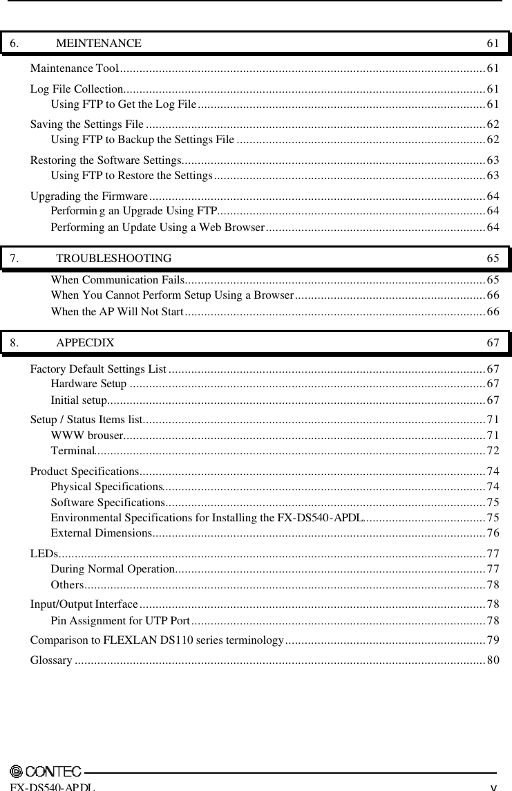
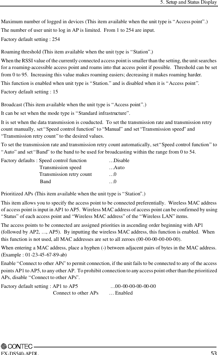
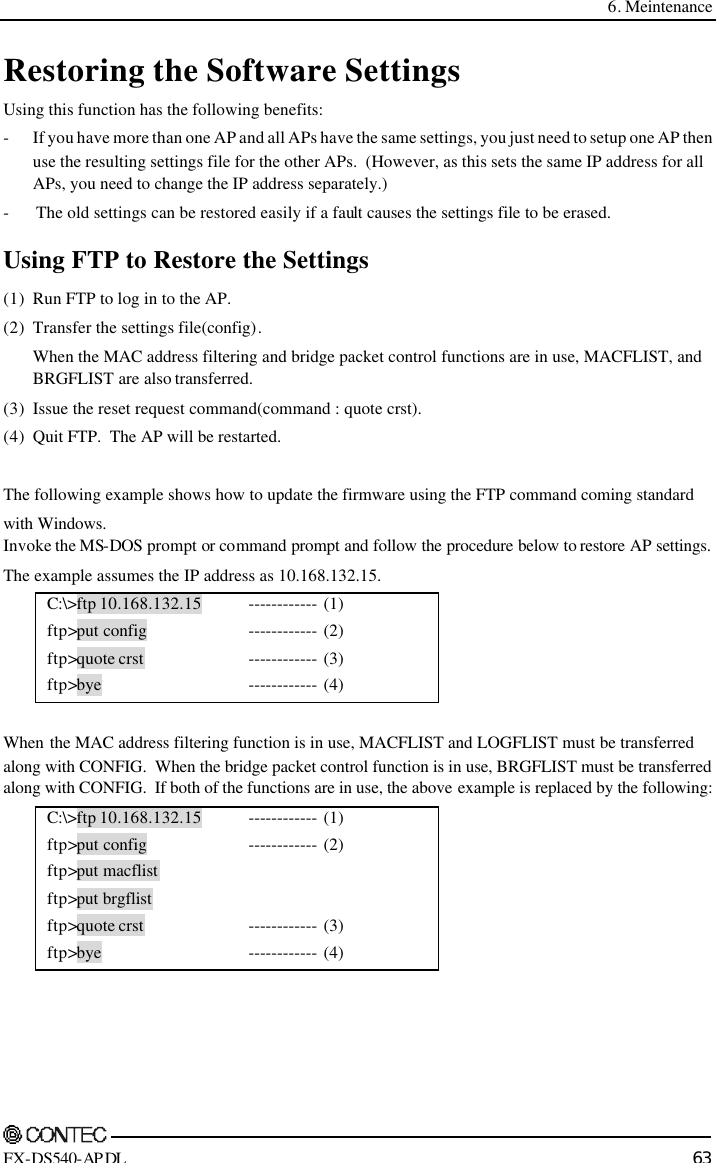
![8. Appecdix 68 FX-DS540-APDL Table 8.1. Initial setup list (2/4) Setting item Setting contents(First default) <Wireless LAN> Interface Enable, Disable Wireless LAN standard IEEE802.11a, IEEE802.11b, IEEE802.11g Wireless connection mode Standard, Compatible, advanced infrastructure Unit type Access point, Station *In compatible mode, you can not select station. ESSID (single-byte alphanumeric characters can be up to 32 characters long and .the password is case sensitive.) LocalGroup AP Channel number 36, 40, 44, 48, 52, 56, 60, 64, 149, 153, 157, 161, 165 : 11a 1, 2, 3, 4, 5, 6, 7, 8, 9, 10, 11 : 11g, 11b *In station, Free is fixed. Transmission rate Auto, 6M, 9M, 12M, 18M, 24M, 36M, 48M, 54M Encryption Disable, WEP, AES Default key #1, #2, #3, #4 Size / key#1 Disalbe, 64bit(10-digits), 128bit(26-digits), 152bit(32-digits) : WEP 128bit(32-digits) : AES Key#1 hexadecimal value ( 0 to 9, a to f or A to F) Size / Key#2 Disable, 64bit(10-digits), 128bit(26-digits), 152bit(32-digits) : WEP 128bit(32-digits) : AES Key#2 hexadecimal value ( 0 to 9, a to f or A to F) Size / key#3 Disable, 64bit(10-digits), 128bit(26-digits), 152bit(32-digits) : WEP 128bit(32-digits) : AES Key#3 hexadecimal value ( 0 to 9, a to f or A to F) Size / Key#4 Disable, 64bit(10-digits), 128bit(26-digits), 152bit(32-digits) : WEP 128bit(32-digits) : AES Key#4 hexadecimal value ( 0 to 9, a to f or A to F) WSL (Wireless security link) Disable, Enable(20-digits) Key WSL hexadecimal value (0 to 9, a to f or A to F) Transmission output MAX, 50%(-3dB), 25%(-6dB) AP MAC address filtering Disable, Enable [List edit : MAX 8192 entries] 11g: The function when selecting IEEE802.11g. AP: The function when unit type is access point. ST: The function when unit type is station.](https://usermanual.wiki/Contec/DS540-APDL.Manual/User-Guide-461972-Page-75.png)
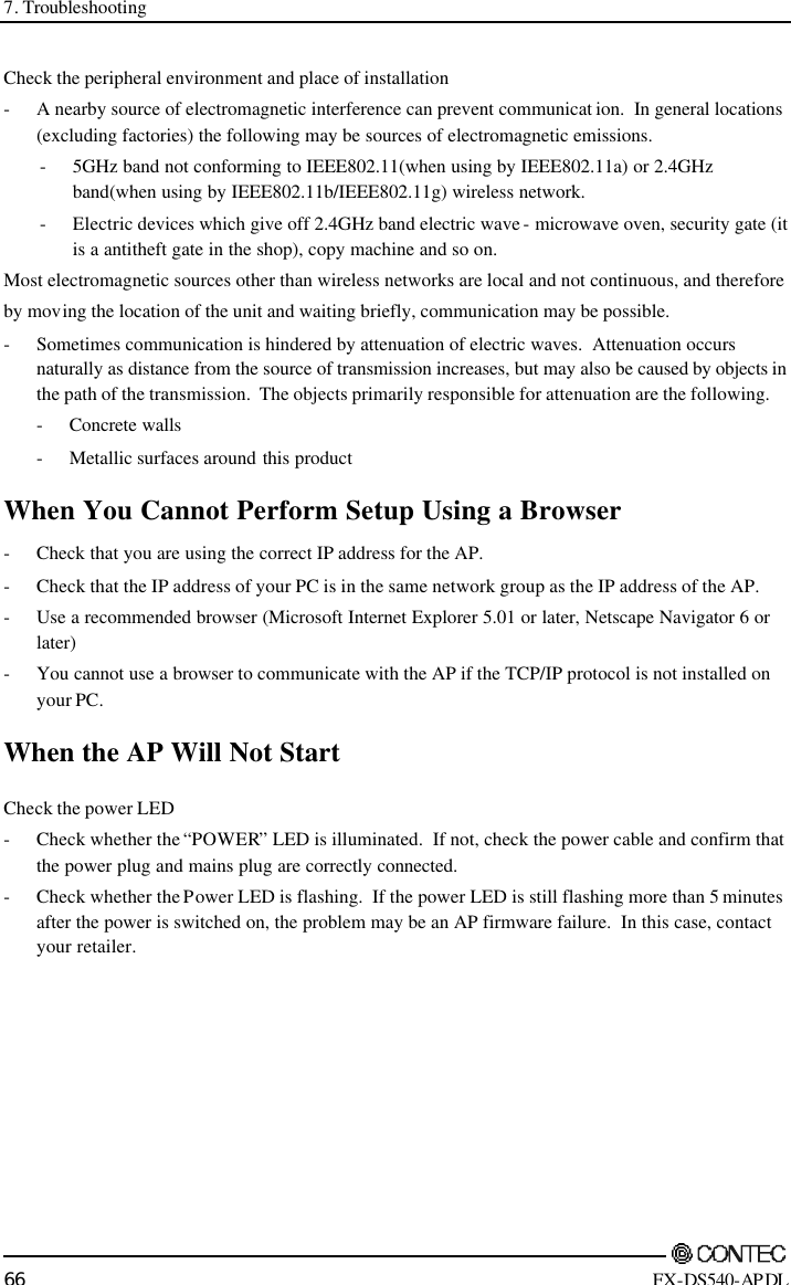
![8. Appecdix FX-DS540-APDL 69 Table 8.1. Initial setup list (3/4) Setting item Setting contents(First default) 11g 802.11g Only mode Disable, Enable 11g Protect mode Enable, Disable 11g Protect type CTS-only, RTS-CTS AP Antenna selecting Auto, 1, 2 AP Broadcasting speed control function Disable, Auto, Enable AP Broadcasting transmission speed Auto, 6M, 9M, 12M, 18M, 24M, 36M, 48M, 54M AP Broadcasting transmission retry count 0, 0 to 10 AP Broadcasting band 0, 0 to 54 AP ESSID security Disable, Enable ST Roaming threshold 15, 0 to 95 : 11a, 11g 24, 0 to 95 : 11b ST Prioritized APs AP 1 00-00-00-00-00-00(No designation) [Speficy the MAC address of AP] ST Prioritized APs AP 2 00-00-00-00-00-00(No designation) [Speficy the MAC address of AP] ST Prioritized APs AP 3 00-00-00-00-00-00(No designation) [Speficy the MAC address of AP] ST Prioritized APs AP 4 00-00-00-00-00-00(No designation) [Speficy the MAC address of AP] ST Prioritized APs AP 5 00-00-00-00-00-00(No designation) [Speficy the MAC address of AP] ST Prioritized APs Connect to other APs Enable, Disable AP Maximum number of logged in devices 254, 1 to 254 <IEEE802.11X> IEEE802.1X function Disable, Enable Re-authentication interval(minutes) 2, 2 to 4320 RADIUS server1, IP address (Set 0.0.0.0 when it is not used./IP address of authentication server.) RADIUS server1, Port number 1812 (UDP port number of RADIUS) RADIUS server1, ESSID (Blank) RADIUS server1, Shared secret (Single-byte alphanumeric characters can be up to 128 characters long. Encryption key to use between authentication server.) RADIUS server2, IP address (Set 0.0.0.0 when it is not used./IP address of authentication server.) RADIUS server2, Port number 1812 (UDP port number of RADIUS) RADIUS server2, ESSID (Blank) RADIUS server2, Shared secret (Single-byte alphanumeric characters can be up to 128 characters long. Encryption key to use between authentication server.) RADIUS server3, IP address (Set 0.0.0.0 when it is not used./IP address of authentication server.) RADIUS server3, Port number 1812 (UDP port number of RADIUS) RADIUS server3, ESSID (Blank) RADIUS server3, Shared secret (Single-byte alphanumeric characters can be up to 128 characters long. Encryption key to use between authentication server.) RADIUS server4, IP address (Set 0.0.0.0 when it is not used./IP address of authentication server.) RADIUS server4, Port number 1812 (UDP port number of RADIUS) RADIUS server4, ESSID (Blank) RADIUS server4, Shared secret (Single-byte alphanumeric characters can be up to 128 characters long. Encryption key to use between authentication server.) 11g: The function when selecting IEEE802.11g. AP: The function when unit type is access point. ST: The function when unit type is station.](https://usermanual.wiki/Contec/DS540-APDL.Manual/User-Guide-461972-Page-76.png)
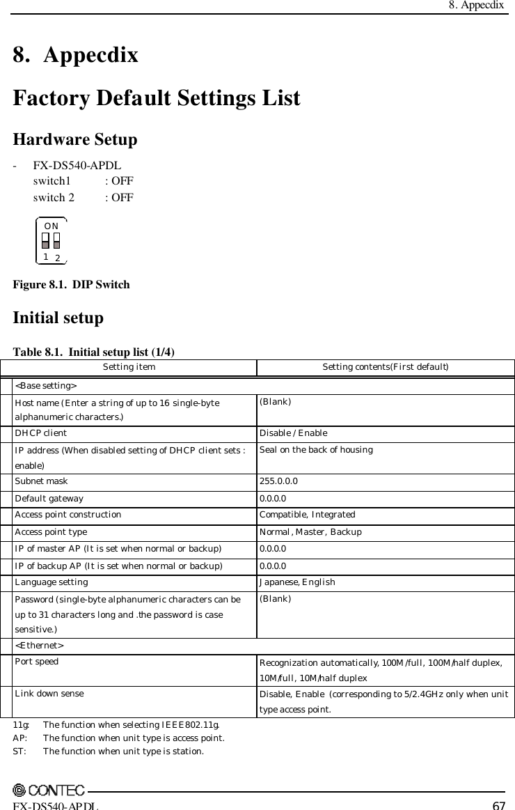
![8. Appecdix 70 FX-DS540-APDL Table 8.1. Initial setup list (4/4) Setting item Setting contents(First default) < Extensions > Bridge Packet Control (MAX 32 entries) Disable, Enable [List edit : MAX 32 entires] Network time, function Disable, Enabled Network time, IP address (IP address of network time server) Network time, time zone +09:00 (Japanese time zone is between +09:00.) Access control Access control, TELNET Enabled, Disable Access control, FTP Enabled, Disable Access control, WEB server Enabled, Disable Access control, administrator IP Disable, Enabled Access control, administrator IP address1 0.0.0.0 Access control, administrator IP address2 0.0.0.0 <Terminal> Baud rate 9600, 1200, 2400, 4800, 19200, 38400, 57600, 115200 <SNMP> SNMP agent function Disable, Enabled Community name (Single-byte alphanumeric characters can be up to 32 characters long and .the password is case sensitive.) public Access permission Read/Write, Read Only Trap destination IP address (1 point) 0.0.0.0 Administrator contact information (sysContact) (Blank), (The string can be up to 32 characters long when all the characters are single-byte characters or up to 16 characters long when they are all double-byte characters.) Device location (sysLocation) (Blank), (The string can be up to 32 characters long when all the characters are single-byte characters or up to 16 characters long when they are all double-byte characters.) Device name (sysName) (Blank), (The string can be up to 32 characters long when all the characters are single-byte characters or up to 16 characters long when they are all double-byte characters.) <Log function> Log function Disable, Enabled Overwriting mode Enabled, Disable Beginning day/time setting Beginning day/time setting function Disable, Enabled Beginning day/time setting Beginning day/time Year Month Day Time Minutes Log setting in detail log-in ON, OFF Log setting in detail log-out ON, OFF Log setting in detail log-in rejection ON, OFF Log setting in detail Roaming ON, OFF 11g: The function when selecting IEEE802.11g. AP: The function when unit type is access point. ST: The function when unit type is station.](https://usermanual.wiki/Contec/DS540-APDL.Manual/User-Guide-461972-Page-77.png)


![Atheros, ABG and Total 802.11 are trademarks of Atheros Communications, Inc. CONTEC CO.,LTD is using the Atheros trademarks with permission from and on behalf of Atheros Communications, Inc. FX-DS540-APDL User’s Manual CONTEC CO., LTD. December 2003 Edition 3-9-31, Himesato, Nishiyodogawa-ku, Osaka 555-0025, Japan Japanese http://www.contec.co.jp/ English http://www.contec.com/ Chinese http://www.contec.com.cn/ No part of this document may be copied or reproduced in any form by any means without prior written consent of CONTEC CO., LTD. [08062003] [12222003] Management No. A-46-824 Parts No. LYDE681](https://usermanual.wiki/Contec/DS540-APDL.Manual/User-Guide-461972-Page-91.png)