Contec FXA2000-G IEEE802.11n/a/b/g Wireless LAN (Access Point/Station) User Manual
Contec Co., Ltd. IEEE802.11n/a/b/g Wireless LAN (Access Point/Station)
Contec >
User Manual
1 FXA2000-G
IEEE802.11n/a/b/g Wireless LAN
(Access point / Station)
FXA2000-G Setup Guide
CONTEC CO.,LTD.
The FXA2000-G is an access point that conforms to IEEE 802.11n/a/b/g wireless networking standards and that
supports a wide range of input power (5 to 30 VDC) and PoE.
Packing Lis
t
- Main unit (FXA2000-G)...1
- Setup Guide...1
- Magnet...2
- Tapping screws...2
- Connector cover (Installed in unit)...1
* You are free to download the manual of this product from the Contec’s website (http://www.contec.com/).
How to Obtain Service
For replacement or repair, return the device freight prepaid, with a copy of the original invoice. Please obtain a Return
Merchandise Authorization number (RMA) from the CONTEC group office where you purchased before returning
any product. *No product will be accepted by CONTEC group without the RMA number. This device sold for OEM
vendor only.
Defalt setting
This product is set up via a network using a Web
browser. Connect this product to the PC with a
LAN cable using the wired LAN connection
and then access the default IP address in a web
browser. This product's default settings are
shown in the table to the right.
Setting Item Default setting
IP Address 192.168.0.1
Subnet Mask 255.255.255.0
ESSID LocalGroup
Security (No input)
User name admin
Password pass
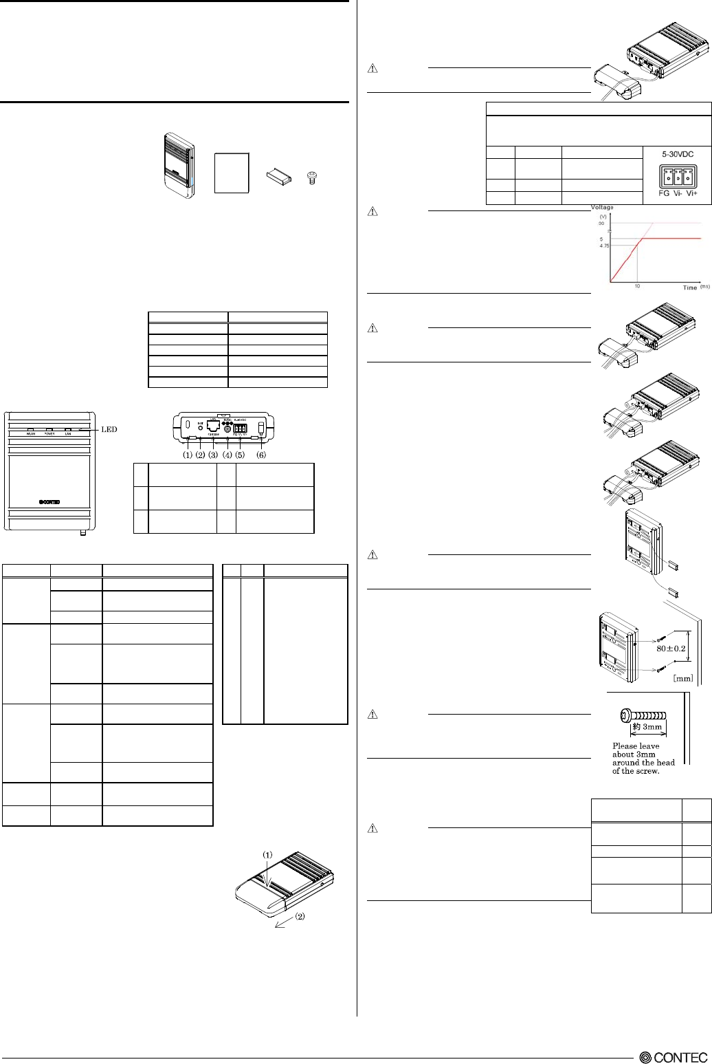
Component Locations
(1) Security slot (2) INIT Switch
(3) LAN port (4) DC JACK
(5) Power connector (6) Power disconnection
prevention hook
LED display INIT Switch
LED name Status Indicator No. Name Operation / function
POWER
ON Indicates that the device is operating. 1 INIT
Used to initialize this
product (reset to factory
default settings). When this
switch is pressed, the
POWER, WLAN, and LAN
LEDs start to flash. If this
switch is released during the
period from when the LEDs
start to flash and until they
turn on (approximately 3
seconds), all of the access
point's settings will be reset
to the factory default when
next started.
Flashing Indicates that the device is being
started (This device turned on)
OFF Indicates that the device is power off.
LAN
ON Indicates that a wired LAN has been
connected.
Flashing
Indicates that the product is
transmitting/receiving data to/from
the connected terminal through wired
LAN.
OFF Indicates that a wired LAN not
logged-in.
WLAN
ON Indicates that the device has been
connected.
Flashing
Indicates data is being transmitted to
or received from the device connected
through wireless LAN.
* When initializing the product by turning the INIT
signal on and off, the LEDs will continue
flashing for a short time after the signal is turned
off. This indicates the internal memory files are
being deleted. If the power is turned off while the
LEDs are flashing, the internal memory files may
be damaged and the product may no longer be
able to start properly. Always restart the product
after the LEDs stop flashing.
OFF Indicates that the device has been no
connected.
POWER/ LAN/
WLAN
Flashing
(simultaneously)
Indicates that firmware has been
reprogrammed. *1
POWER/LAN Blinking twice /
On DHCP error
*1 Not include LogFile
Removing the connector cove
r
While lightly pushing vertically on the center of the connector cover [(1) in the
diagram], slide the entire cover [(2) in the diagram], and remove the connector
cover.
Power Supply
When using the AC adapter (F
X
-
AC052
)
Pass the DC plug through the connector cover opening and connect the AC
adapter's DC plug to the product's DC jack. You can prevent the DC plug
from being pulled out by hooking the cord on the power disconnection
prevention hook located on the connector section.
CAUTION
When supplying power via PoE, do not use the power supplied from the power connector or the AC
adapter.
When supplying power from the power
connector
Power can be externally supplied using
the power connector. Use the
components indicated to the right for
the power cable or use equivalent
components.
Function
Power connector: MC1,5/3-ST-3,5(PHOENIX CONTACT),
Cable: AWG28-16(on the condition that the cable length satisfies the power
specifications)
Pin No. Signal name Meaning
1 Vi+ Power supply
(5 to 30 VDC ±5%)
2 Vi- Power supply (GND)
3 FG Frame ground
CAUTION
- Carefully manufacture the power cable taking care not to mistake the wiring. In particular, if
the power cable is used with mistaken housing pin numbers, there is a risk of malfunction or
accidents.
- Input voltage range: 5 to 30 VDC ± 5%. Use a power supply that rises to 4.75 VDC or
higher in the input voltage range within 10 ms. There is a risk of damage to the device or
accident if a power supply outside this range is used.
- When supplying power with the AC adapter, do not use power supplied from the power
connector.
LAN Por
t
Connect a LAN cable to this product's LAN port.
CAUTION
- Ensure that the cable length between this product and a PC or hub is 100 m or shorter.
- When supplying power via PoE or when using 100BASE-TX, use a Category 5 or better
cable. When using 10BASE-T, use a Category 3 or better cable.
Attaching the security wir
e
A commercially available security wire can be attached to the security slot
located on the connector section.
Recommended security wires:
- KOKUYO EAS-L41, Buffalo BSL4DS, SANWA SUPPLY SL-31S
Attaching the connector cove
r
Attach the connector cover to the product.
Using magnets for installation
Attach the included magnets to the two magnet attachment locations on the
back of the access point. To attach the magnets, push them in the direction of
the arrow to insert them entirely into the attachment holes.
CAUTION
- Do not place the magnets near items that are susceptible to magnetic fields.
- If the product is moved while attached to a steel desk or other object, it may damage the
painted surface.
Using the included screws for installation
Referring to the diagram to the right, drive the two included screws into a
sturdy, vertical wall surface while leaving around 3 mm of the screws sticking
out from the wall surface.
Hook the attachment holes on the back of the access point to the heads of the
screws to attach it.
Due to the characteristics of wireless networks, the signal will spread in a
wider area when the access point is installed in a highly-visible location, so w
e
recommend you install it in a location as high as possible.
N
ote that the placing the product near metal or concrete walls (including steel
beams) may cause the signal quality to degrade.
CAUTION
- The access point cannot be installed on the ceiling using the screws due to the danger of
falling. If a ceiling installation is required, use the optional installation bracket.
- Caution: If the product's ventilation holes are blocked, the product may malfunction due to a
rise in internal temperature.
DFS function
When set to DFS-supported channels (5 GHz only), if radar waves are
detected, the channel must be changed in order to avoid radio wave
interference with weather radars and other radars, so note the following.
CAUTION
- After starting, the channel is checked for radar waves for one minute, so at a minimum, one minute or
longer is required.
- If radar waves are detected during startup or while started, the access point may start on another channel
since it must use a channel different from the set channel.
- Even after starting with the set DFS-supported channel, the channel may change while running.
- If radar waves are detected, the radio waves must stop for 30 minutes, so the detected channel cannot be
used for 30 minutes.
DFS-supported channel (Frequency: 5GHz)
Channel DFS
function
W52: 36, 40, 44, 48 Not
supported
W53: 52, 56, 60, 64 Effective
W56: 100, 104, 108, 112, 116, 120,
124, 128, 132, 136, 140
Effective
W58: 149, 153, 157, 161, 165 Not
supported
FXA2000-G Setup Guide
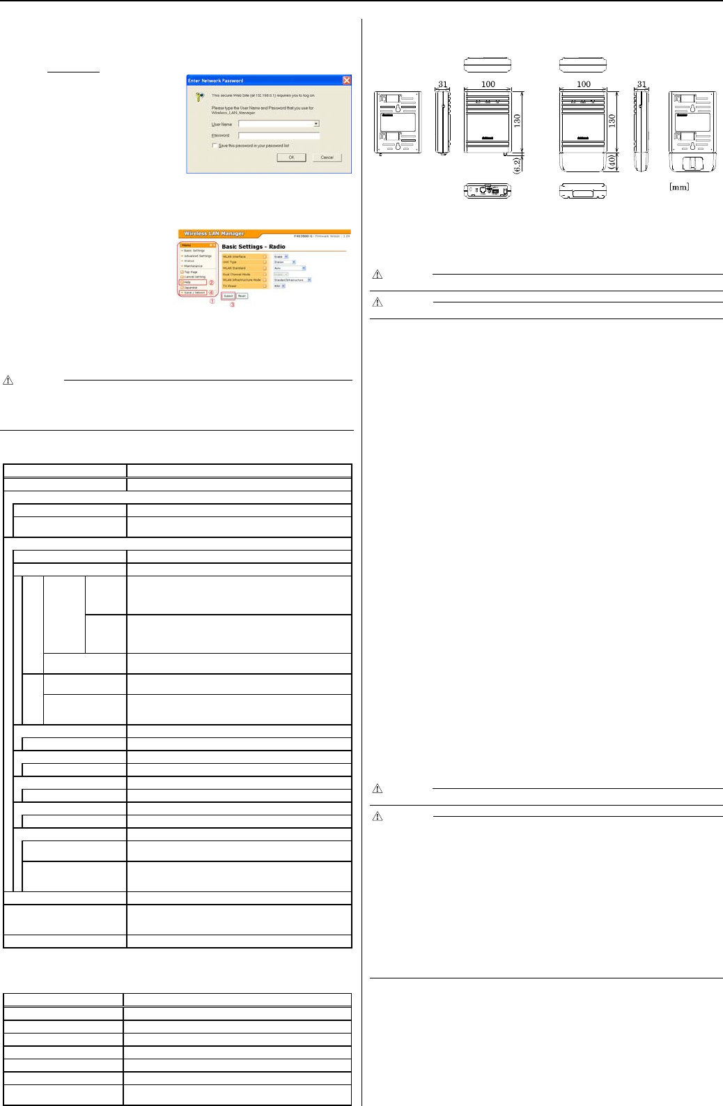
Connecting to This Product Using Web Browser
Start up a Web browser and enter the IP address of this product after “http: //” in the address bar. If connecting for the first
time, enter the default IP address. When the default setting IP address is 192.168.0.1, enter as follows.
http://192.168.0.1/
Connecting to this product displays the “Wi
r
eless LAN
Manager” login screen/ If the login screen is not displayed, the
IP address setting for PC, browser settings, or the URL entered
in the address bar of the browser may be incorrect.
Enter a password on the login screen and then click “Login” to log in.
When connecting for the first time, Default setting is Username=”admin” & Password=”pass” and just click “OK” .
If the login is successful, the following setup screen will be displayed after a little while.
Setup Using Web Browser
Select the desi
r
ed setting items from the opened menu (1).
Information such as setting items will be displayed in the
right-hand frame.
For more information about a setting item, please refer to
"help" (2).
Click “Submit” (3) after changing settings on each page to
temporarily save the settings in this product.
The settings become enabled when the product is restarted
after all the setup procedure is completed and the settings
are stored. Click “Save & Reboot” (4) on the left-hand
menu.
There will be no problem if you just save the settings now but reboot the product later when necessary. In this case, saving
the settings does not actually change the settings of the product. Therefore, make sure to reboot the product later
CAUTION
It takes approximately 5 - 10 seconds to save settings (writing to internal flash memory). During that period, the LEDs for POWER, LAN and
WLAN at the front part of the main unit blink simultaneously. Do not reboot or turn off the product until the screen indicates the completion of the
saving process. The setup file data and firmware data may be damaged and the product may not operate properly if it is rebooted or switched off
during the saving process.
Specifications
Name Specification
Unit type Access point / Station / Repeater
Wired LAN
Ethernet standard IEEE802.3(10BASE-T), IEEE802.3u(100BASE-TX), IEEE802.3af
Port Speed / Communication type /
Number of ports 10/100Mbps/Half Duplex, Full Duplex/ 1
Wireless LAN
Transmission format IEEE802.11n, IEEE802.11a, IEEE802.11b, IEEE802.11g
Channel*1
USA
(FCC)
IEEE802.11n
IEEE802.11a
Access point /
Repeater
5GHz: 24h(36, 40, 44, 48ch[W52], 52, 56, 60, 64ch [W53],
100, 104, 108, 112, 116, 132, 136, 140ch [W56]
149, 153, 157, 161, 165ch [W58] )
Station
5GHz: 24h(36, 40, 44, 48ch[W52], 52, 56, 60, 64ch [W53],
100, 104, 108, 112, 116, 132, 136, 140ch [W56]
149, 153, 157, 161, 165ch [W58] )
IEEE802.11n IEEE802.11g
IEEE802.11b 2.4GHz: 11ch (1 - 11)
EU
(CE)
IEEE802.11n
IEEE802.11a
5GHz: 24h(36, 40, 44, 48ch[W52], 52, 56, 60, 64ch[W53],
100, 104, 108, 112, 116, 120, 124 , 128, 132, 136, 140ch[W56],
IEEE802.11n
IEEE802.11g
IEEE802.11b
2.4GHz: 13ch (1 - 13)
IEEE802.11n
Data transmission speed *2 300 - 6.5Mbps[MSC0 - 15, Short/Long GI] (Fixed/Auto)
IEEE802.11a
Data transmission speed *2 54, 48, 36, 24, 18, 12, 9, 6Mbps (Fixed/Auto)
IEEE802.11b
Data transmission speed *2 11, 5.5, 2, 1Mbps (Fixed/Auto)
IEEE802.11g
Data transmission speed *2 54, 48, 36, 24, 18, 12, 9, 6Mbps (Fixed/Auto)
Security
IEEE802.11n WPA(AES), WPA2(AES), WPA-PSK(AES), WPA2-PSK(AES),
WSL (combination mentioned above are possible)
IEEE802.11a/b/g
WEP(open/ Shared Key /Auto), WPA(AES, TKIP), WPA-PSK(AES,TKIP),
WPA2(AES, TKIP), WPA2-PSK(AES,TKIP), IEEE802.1X(EAP-TLS, PEAP),
WSL (combination mentioned above are possible)
Antenna chip-antenna x 2 MIMO
External dimension (mm)
Unit only: 136.2(W) x 100.0(D) x 31.0(H) including power cable disconnection
prevention hook
With connector cover attached: 170.0(W) x 100.0(D) x 31.0(H)
Weight 250g (Unit only), 270g (With connector cover attached)
*1 Varies depending on the country in which the product is used
*2 These are theoretical values based on their respective wireless LAN standards; they do not indicate actual data transfer rates.
Environmental Specifications
Name Specification
Input voltage range 5VDC ± 5% (DC Jack), 5 - 30VDC ± 5% (power connector), 36 - 57VDC (PoE)
Rating input current 1.05A (5VDC input), 0.19A (30VDC input) (Max.), 0.15A (PoE input 48V)
Operating ambient temperature 0 - 40°C
Operating ambient humidity 10 - 90%RH (No condensation)
Floating dust particles Not extreme
Corrosive gases None
Permitted transient power failure 17ms or less (100VAC@25°C)
An automatic reset is performed when low voltage is detected.
External Dimensions
External dimensions (Unit only) External dimensions (connector cover attached)
Safety Information
This document provides safety information using the following symbols to prevent accidents resulting in injury or death and the destruction of
equipment and resources. Understand the meanings of these labels to operate the equipment safely.
DANGER
DANGER indicates an imminently hazardous situation which, if not avoided, will result in death or serious injury.
CAUTION
CAUTION indicates a potentially hazardous situation which, if not avoided, may result in minor or moderate injury or in property damage.
Precaution on use
It is prohibited to modify the inside of this product. The product cannot be used in any country other than those authorized for use.
Security Precautions
Wireless LAN uses radio waves instead of LAN cables to send and receive data between a computer and a wireless access point, making it possible to freely establish a LAN
connection within a range of the radio waves. However, radio waves can be received through obstacles, such as walls, when within the range. Therefore, if security settings
are not made, the following problems may occur. Unauthorized viewing of data An unauthorized third party can intercept the radio waves and view e-mail messages and
personal information, such as user ID and password or your credit card information. Unauthorized access An unauthorized third party can access a personal or corporate
network and cause the following damage:
- Intercepting personal information and confidential information (information leak)
- Using a false identity to communicate and disclose information illegally (identity theft)
- Changing and transmitting intercepted data (tampering)
- Damaging data and systems by spreading a computer virus (destruction)
The wireless LAN card and wireless access point have security features to counter these problems. Using the security settings of the wireless LAN equipment can help
prevent these problems from occurring. The security settings of the wireless LAN equipment are not configured at the time of purchase.
To reduce security problems, configure all security settings of the wireless LAN equipment according to the manual before using the wireless LAN card and wireless access
point. Please be aware that the security settings do not provide complete security protection due to wireless LAN specifications. If you are unable to configure the security
settings yourself, please contact your local authorized dealer. The customer is responsible for configuring the security settings and understanding the risks inherent in using the
product without the security settings configured.
Notes on Radio Interface
The 2.4 GHz band used by this product covers the operating frequencies of mobile-identification local radio stations (requiring the license), specific low-power radio stations
(requiring no license) and amateur wireless stations (requiring the license) as well as industrial, scientific, and medical equipment such as microwave ovens.
1. Before using this product, make sure that there is no mobile-identification local radio station, specific low-power radio station and amateur wireless station operating near
the product.
2. If the product should cause radio interface with any mobile-identification local radio station or specific low-power radio station, immediately change the operating
frequency to avoid the radio interface.
3. Placing wireless terminals near each other may slows down their data rate because of their mutual interference. You should allow a minimum clearance of about 1m
between stations, 3m between access point and station, and 3m between access points.
4. Contact your local retailer or CONTEC if the product has trouble such as recurrent radio interface with mobile-identification local radio stations or specific low-power
radio stations
About the speed mark
The link speed shown for the transmission rate in this manual, the setup screens, and elsewhere is the theoretical maximum value based on the wireless LAN standard and
does not represent the actual data transfer rate.
Usage limitation
This product has not been developed or manufactured to be used in systems including the equipment which is directly related to human lives *1 or the equipment which
involves human safety and may significantly affect the maintenance of public functions *2. Therefore, do not use the product for such purposes. In addition, do not use the
product within 20cm from a human body on a regular basis.
*1: Medical devices such as life-support equipment and devices used in an operating theater.
*2: Main control systems at nuclear power stations, safety maintenance systems at nuclear facilities, other important safety-related systems, operation control systems within
group transport systems, air-traffic control systems, etc.
If using the IEEE802.11a standard, ensure that you comply with all relevant laws in the country of use.
Handling Precautions
DANGER
Do not use the product where it is exposed to flammable or corrosive gas. Doing so may result in an explosion, fire, electric shock, or failure.
CAUTION
- This product contains precision electronic elements and must not be used in locations subject to physical shock or strong vibration. Otherwise, the board may
malfunction, overheat, or cause a failure.
- Do not use or store this device in high temperature or low temperature surroundings, or do not expose it to extreme temperature changes. Otherwise, the board may
malfunction, overheat, or cause a failure.
- Do not use or store this device where it is exposed to direct sunlight or near stoves or other sources of heat. Otherwise, the board may malfunction, overheat, or cause a
failure.
- Do not use or store this device near strong magnetic fields or devices emitting electromagnetic radiation. Otherwise, the board may malfunction, overheat, or cause a
failure.
- If an unusual smell or overheat is noticed, unplug the power cable immediately In the event of an abnormal condition or malfunction, please contact your retailer.
- The specifications of this product are subject to change without notice for enhancement and quality improvement. Even when using the product continuously, be sure to
read the manual and understand the contents.
- Do not block the ventilation holes by placing objects on the produc
- Do not attempt to modify this device. The manufacturer will bear no responsibility whatsoever for the device if it has been modified.
- The product must always be associated with the setup guide.
- Regardless of the foregoing statements, CONTEC is not liable for any damages whatsoever (including damages for loss of business profits) arising out of the use or
inability to use this CONTEC product or the information contained herein.
Federal Communications Commission
This equipment has been tested and found to comply with the limits for a Class A digital device, pursuant to part 15 of the FCC Rules.
These limits are designed to pro-vide reasonable protection against harmful interference when the equipment is operate din a
commercial environment. This equipment generates, uses, and can radiate radiofrequency energy and, if not installed and used in
accordance with the instruction manual, may cause harmful interference to radio communications. Operation of this equipment in a
residential area is likely to cause harmful interference in which case the user will be required to correct the interference at his own
expense.
If this equipment does cause harmful interference to radio or television reception, which can be determined by turning the equipment off
and on, the user is encouraged to try to correct the interference by one of the following measures:
- Reorient or relocate the receiving antenna.

FXA2000 セットアップガイド
- Increase the separation between the equipment and receiver.
- Connect the equipment into an outlet on a circuit different from that to which the receiver is connected.
- Consult the dealer or an experienced radio/TV technician for help.
FCC Caution: Any changes or modifications not expressly approved by the party responsible for compliance could void the user's
authority to operate this equipment.
Operations in the 5.15-5.25GHz band are restricted to indoor usage only.
This device complies with part 15 of the FCC Rules. Operation is subject to the following two conditions:
(1) This device may not cause harmful interference, and
(2) This device must accept any interference received, including interference that may cause undesired operation. This
transmitter must not be co-located or operating in conjunction with any other antenna or transmitter.
Radiation Exposure Statement: This equipment complies with FCC radiation exposure limits set forth for an uncontrolled
environment. This equipment should be installed and operated with minimum distance 20cm between the radiator & your
body.
AT BE BG CY CZ DK
EE FI FR* DE GR HU
IE IT LV LT LU MT
NL PL PT RO SK SI
ES SE GB IS LI NO
CH
* Outdoor use limited to 10mW eirp within the band 2454-2483.5MHz
CONTEC CO.,LTD.
3-9-31, Himesato, Nishiyodogawa-ku, Osaka 555-0025, Japan
December 2012 Editio
n
Japa
n
es
e
http://www.contec.co.jp
/
English http://www.contec.com
/
Chinese http://www.contec.com.cn/ NA02429
(
LYPZ251
)
[12062012]
N
o part of this document may be copied or reproduced in any form by any means without prior written consent of CONTEC CO., LTD.