Contec FXE2000-DG Wireless LAN Adapter User Manual NA03126BODY 20140407
Contec Co., Ltd. Wireless LAN Adapter NA03126BODY 20140407
UserManual.wiki
>
Contec
>
FXE2000 DG User Manual
User Manual.pdf
Navigation menu
Upload a User Manual
Namespaces
Wiki Guide
HTML
PDF
Info
Views
User Manual
Discussion / Help
Navigation
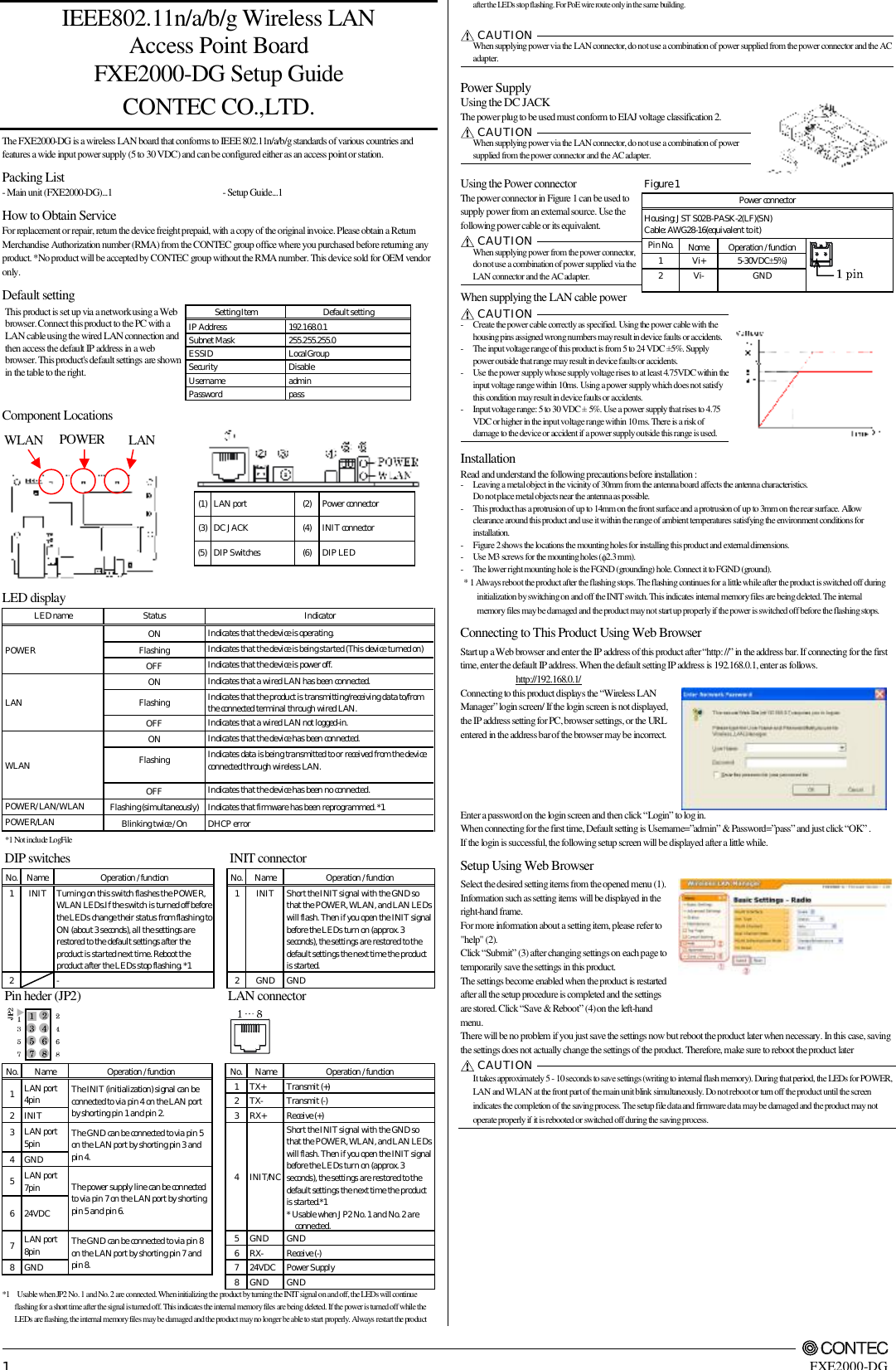
![FXE2000-DG Setup Guide Specifications Name Specification Wired LAN Ethernet standard IEEE802.3(10BASE-T), IEEE802.3u(100BASE-TX) Port Speed 10/100Mbps/Half Duplex, Full Duplex/ 1 Wireless LAN Transmission format IEEE802.11n, IEEE802.11a, IEEE802.11b, IEEE802.11g Channel*1 IEEE802.11n IEEE802.11a Access Point/ Repeater 9ch(36, 40, 44, 48ch[W52], 149, 153, 157, 161, 165ch [W58] ) Station 24h(36, 40, 44, 48ch[W52], 52, 56, 60, 64ch [W53], 100, 104, 108, 112, 116, 132, 136, 140ch [W56] 149, 153, 157, 161, 165ch [W58] ) IEEE802.11n IEEE802.11g IEEE802.11b 2.4GHz: 11ch (1 - 11) IEEE802.11n Data transmission speed *2 300 - 6.5Mbps[MSC0 - 15, Short/Long GI] (Fixed/Auto) IEEE802.11a Data transmission speed *2 54, 48, 36, 24, 18, 12, 9, 6Mbps (Fixed/Auto) IEEE802.11b Data transmission speed *2 11, 5.5, 2, 1Mbps (Fixed/Auto) IEEE802.11g Data transmission speed *2 54, 48, 36, 24, 18, 12, 9, 6Mbps (Fixed/Auto) Security IEEE802.11n WPA(AES), WPA2(AES), WPA-PSK(AES), WPA2-PSK(AES), WSL(combination mentioned above are possible) IEEE802.11a/b/g WEP(open/ Shared Key /Auto), WPA(AES, TKIP), WPA-PSK(AES,TKIP), WPA2(AES, TKIP), WPA2-PSK(AES,TKIP), IEEE802.1X(EAP-TLS, PEAP), WSL(combination mentioned above are possible) Antenna chip-antenna×2 MIMO External dimension (mm) 61.0(W) x 89.2(D) x 17.5(H) Weight 50g *1 Varies depending on the country in which the product is used *2 These are theoretical values based on their respective wireless LAN standards; they do not indicate actual data transfer rates. Environmental Specifications Name Specification Input voltage range 5VDC±5% (DC Jack), 5 - 30VDC±5% (power connector), 24VDC±10% (PoE) Rating input current 1.05A (5VDC input), 0.19A (30VDC input) (Max.), 0.24A (PoE input 24V) Operating ambient temperature 0 - 50°C Operating ambient humidity 10 - 90%RH (No condensation) Floating dust particles Not extreme Corrosive gases None External Dimensions Figure 2 Safety Information This document provides safety information using the following symbols to prevent accidents resulting in injury or death and the destruction of equipment and resources. Understand the meanings of these labels to operate the equipment safely. DANGER DANGER indicates an imminently hazardous situation which, if not avoided, will result in death or serious injury. CAUTION CAUTION indicates a potentially hazardous situation which, if not avoided, may result in minor or moderate injury or in property damage. Precaution on use It is prohibited to modify the inside of this product. The product cannot be used in any country other than those authorized for use. Security Precautions Wireless LAN uses radio waves instead of LAN cables to send and receive data between a computer and a wireless access point, making it possible to freely establish a LAN connection within a range of the radio waves. However, radio waves can be received through obstacles, such as walls, when within the range. Therefore, if security settings are not made, the following problems may occur. Unauthorized viewing of data An unauthorized third party can intercept the radio waves and view e-mail messages and personal information, such as user ID and password or your credit card information. Unauthorized access An unauthorized third party can access a personal or corporate network and cause the following damage: - Intercepting personal information and confidential information (information leak) - Using a false identity to communicate and disclose information illegally (identity theft) - Changing and transmitting intercepted data (tampering) - Damaging data and systems by spreading a computer virus (destruction) The wireless LAN card and wireless access point have security features to counter these problems. Using the security settings of the wireless LAN equipment can help prevent these problems from occurring. The security settings of the wireless LAN equipment are not configured at the time of purchase. To reduce security problems, configure all security settings of the wireless LAN equipment according to the manual before using the wireless LAN card and wireless access point. Please be aware that the security settings do not provide complete security protection due to wireless LAN specifications. If you are unable to configure the security settings yourself, please contact your local authorized dealer. The customer is responsible for configuring the security settings and understanding the risks inherent in using the product without the security settings configured. Notes on Radio Interface The 2.4 GHz band used by this product covers the operating frequencies of mobile-identification local radio stations (requiring the license), specific low-power radio stations (requiring no license) and amateur wireless stations (requiring the license) as well as industrial, scientific, and medical equipment such as microwave ovens. 1. Before using this product, make sure that there is no mobile-identification local radio station, specific low-power radio station and amateur wireless station operating near the product. 2. If the product should cause radio interface with any mobile-identification local radio station or specific low-power radio station, immediately change the operating frequency to avoid the radio interface. 3. Placing wireless terminals near each other may slows down their data rate because of their mutual interference. You should allow a minimum clearance of about 1m between stations, 3m between access point and station, and 3m between access points. 4. Contact your local retailer or CONTEC if the product has trouble such as recurrent radio interface with mobile-identification local radio stations or specific low-power radio stations About the speed mark The link speed shown for the transmission rate in this manual, the setup screens, and elsewhere is the theoretical maximum value based on the wireless LAN standard and does not represent the actual data transfer rate. Usage limitation This product has not been developed or manufactured to be used in systems including the equipment which is directly related to human lives *1 or the equipment which involves human safety and may significantly affect the maintenance of public functions *2. Therefore, do not use the product for such purposes. In addition, do not use the product within 20cm from a human body on a regular basis. *1: Medical devices such as life-support equipment and devices used in an operating theater. *2: Main control systems at nuclear power stations, safety maintenance systems at nuclear facilities, other important safety-related systems, operation control systems within group transport systems, air-traffic control systems, etc. If using the IEEE802.11a standard, ensure that you comply with all relevant laws in the country of use. Outdoor use of IEEE802.11a is prohibited in some countries. It is not possible to use it by limiting Radio Law in Japan. Handling Precautions DANGER Do not use the product where it is exposed to flammable or corrosive gas. Doing so may result in an explosion, fire, electric shock, or failure. CAUTION - This product contains precision electronic elements and must not be used in locations subject to physical shock or strong vibration. Otherwise, the board may malfunction, overheat, or cause a failure. - Do not use or store this device in high temperature or low temperature surroundings, or do not expose it to extreme temperature changes. Otherwise, the board may malfunction, overheat, or cause a failure. - Do not use or store this device where it is exposed to direct sunlight or near stoves or other sources of heat. Otherwise, the board may malfunction, overheat, or cause a failure. - Do not use or store this device near strong magnetic fields or devices emitting electromagnetic radiation. Otherwise, the board may malfunction, overheat, or cause a failure. - If an unusual smell or overheat is noticed, unplug the power cable immediately In the event of an abnormal condition or malfunction, please contact your retailer. - The specifications of this product are subject to change without notice for enhancement and quality improvement. Even when using the product continuously, be sure to read the manual and understand the contents. - Do not attempt to modify this device. The manufacturer will bear no responsibility whatsoever for the device if it has been modified. - The product must always be associated with the instruction manual. - Regardless of the foregoing statements, CONTEC is not liable for any damages whatsoever (including damages for loss of business profits) arising out of the use or inability to use this CONTEC product or the information contained herein. Federal Communications Commission This equipment has been tested and found to comply with the limits for a Class A digital device, pursuant to part 15 of the FCC Rules. These limits are designed to pro-vide reasonable protection against harmful interference when the equipment is operate din a commercial environment. This equipment generates, uses, and can radiate radiofrequency energy and, if not installed and used in accordance with the instruction manual, may cause harmful interference to radio communications. Operation of this equipment in a residential area is likely to cause harmful interference in which case the user will be required to correct the interference at his own expense. If this equipment does cause harmful interference to radio or television reception, which can be determined by turning the equipment off and on, the user is encouraged to try to correct the interference by one of the following measures: - Reorient or relocate the receiving antenna. - Increase the separation between the equipment and receiver. - Connect the equipment into an outlet on a circuit different from that to which the receiver is connected. - Consult the dealer or an experienced radio/TV technician for help. FCC Caution: Any changes or modifications not expressly approved by the party responsible for compliance could void the user's authority to operate this equipment. This device complies with part 15 of the FCC Rules. Operation is subject to the following two conditions: (1) This device may not cause harmful interference, and (2) This device must accept any interference received, including interference that may cause undesired operation. This transmitter must not be co-located or operating in conjunction with any other antenna or transmitter. Operations in the 5.15-5.25GHz band are restricted in indoor usage only. Radiation Exposure Statement: This equipment complies with FCC radiation exposure limits set forth for an uncontrolled environment. This equipment should be installed and operated with minimum distance 20cm between the radiator & your body. This device is intended only for OEM integrators under the following conditions: - The antenna must be installed such that 20 cm is maintained between the antenna and users, and - The transmitter module may not be co-located with any other transmitter or antenna. As long as 2 conditions above are met, further transmitter test will not be required. However, the OEM integrators is still responsible for testing their end-product for any additional compliance requirements required with this module installed IMPORTANT NOTE: In the event that these conditions can not be met (for example certain laptop configurations or co-location with another transmitter), then the FCC authorization is no longer considered valid and the FCC ID can not be used on the final product. In these circumstances, the OEM integrator will be responsible for re-evaluating the end product (including the transmitter) and obtaining a separate FCC authorization. End Product Labeling this transmitter module is authorized only for use in device where the antenna may be installed such that 20 cm may be maintained between the antenna and users. The final end product must be labeled in a visible area with the following: “Contains FCC ID: PQRFXE2000-DG”. The grantee's FCC ID can be used only when all FCC compliance requirements are met. Manual Information to the End User the OEM integrator has to be aware not to provide information to the end user regarding how to install or remove this RF module in the user’s manual of the end product which integrates this module. The end user manual shall include all required regulatory information/warning as show in this manual. Copyright 2012 CONTEC CO., LTD. All Rights Reserved. CONTEC CO.,LTD. 3-9-31, Himesato, Nishiyodogawa-ku, Osaka 555-0025, Japan February 2014 EditionJapanese http://www.contec.co.jp/ English http://www.contec.com/ Chinese http://www.contec.com.cn/ NA03126 (LYRD511)[07052012]No part of this document may be copied or reproduced in any form by any means without prior written consent of CONTEC CO., LTD.](https://usermanual.wiki/Contec/FXE2000-DG/User-Guide-2237058-Page-2.png)