Contec NZ2WL-US Wireless LAN Adapter User Manual NA01085BODY160610x
Contec Co., Ltd. Wireless LAN Adapter NA01085BODY160610x
UserManual.wiki
>
Contec
>
NZ2WL-US User Manual
>
User Manual
Contents
1.
User’s Manual
2.
User Manual
User Manual
Navigation menu
Upload a User Manual
Namespaces
Wiki Guide
HTML
PDF
Info
Views
User Manual
Discussion / Help
Navigation

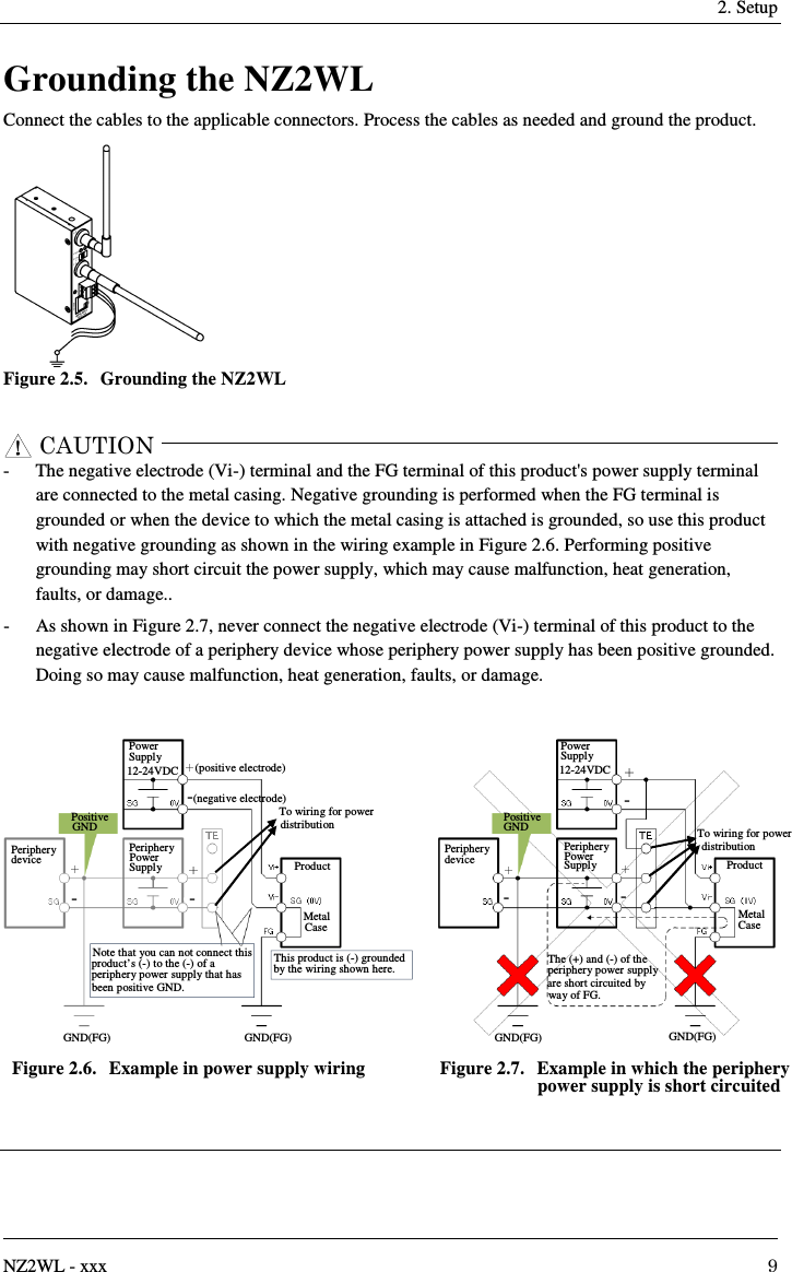
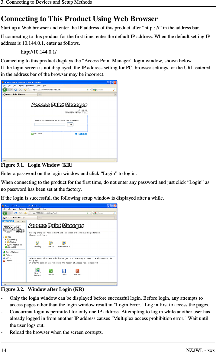
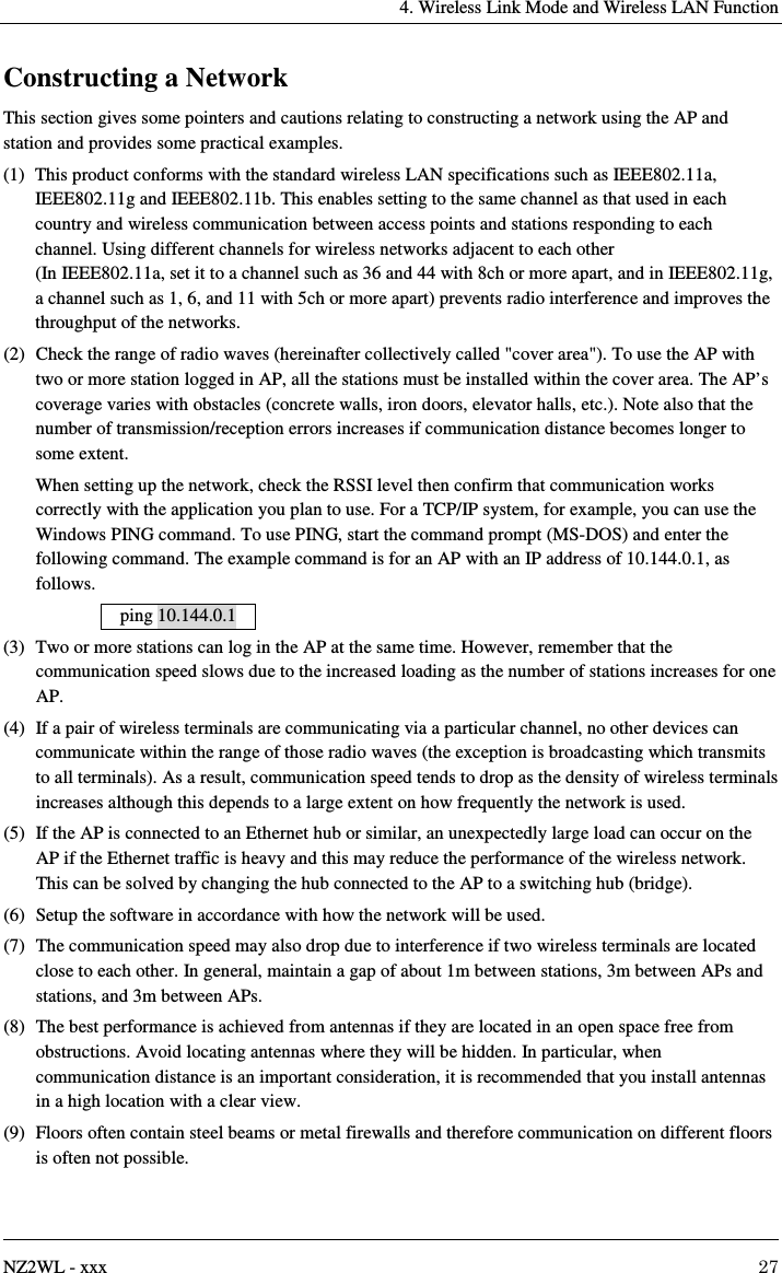
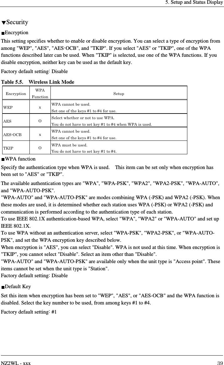
![3. Connecting to Devices and Setup Methods 12 NZ2WL - xxx 3. Connecting to Devices and Setup Methods This product is set up via a network using a Web browser or TELNET. Follow the setup procedure below once the product is set up. Setup Methods Although the NZ2WL-xxx can be set up precisely to construct an advanced wireless LAN environment, there are two different setup methods available: web browser and TELNET. Web browser - Settings are easy with a graphical display and a help function. TELNET - This terminal setting uses TELNET. - Only text is displayed, but settings are easy and quick. Preparation before Setup Since the product is set up via network, use a personal computer that can be connected to the network. Connect the personal computer to the network and use a Web browser or TELNET for setting. Connecting the product for the first time (1) Connect this product to PC on a wired LAN. (2) Select an IP address 10.XXX.XXX.XXX (e.g. 10.0.0.1) for the PC, which is not the same address as for this product. And then set the subnet mask to 255.0.0.0. Windows: Click [Start] - [Control Panel] - [Network Connection], and then right-click the icon for local area connection to open up the [Properties] screen. Select [Internet Protocol (TCP/IP)] from the [General] tab and click [Properties]. Set up the IP address and subnet mask, and if necessary, default gateway and DNS server on the opened [Internet protocol (TCP/IP) properties] window. Changing the settings (1) Connect this product to PC on a wired LAN. (2) Set the network address of the PC to the same network address as for this product.](https://usermanual.wiki/Contec/NZ2WL-US.User-Manual/User-Guide-3025295-Page-26.png)
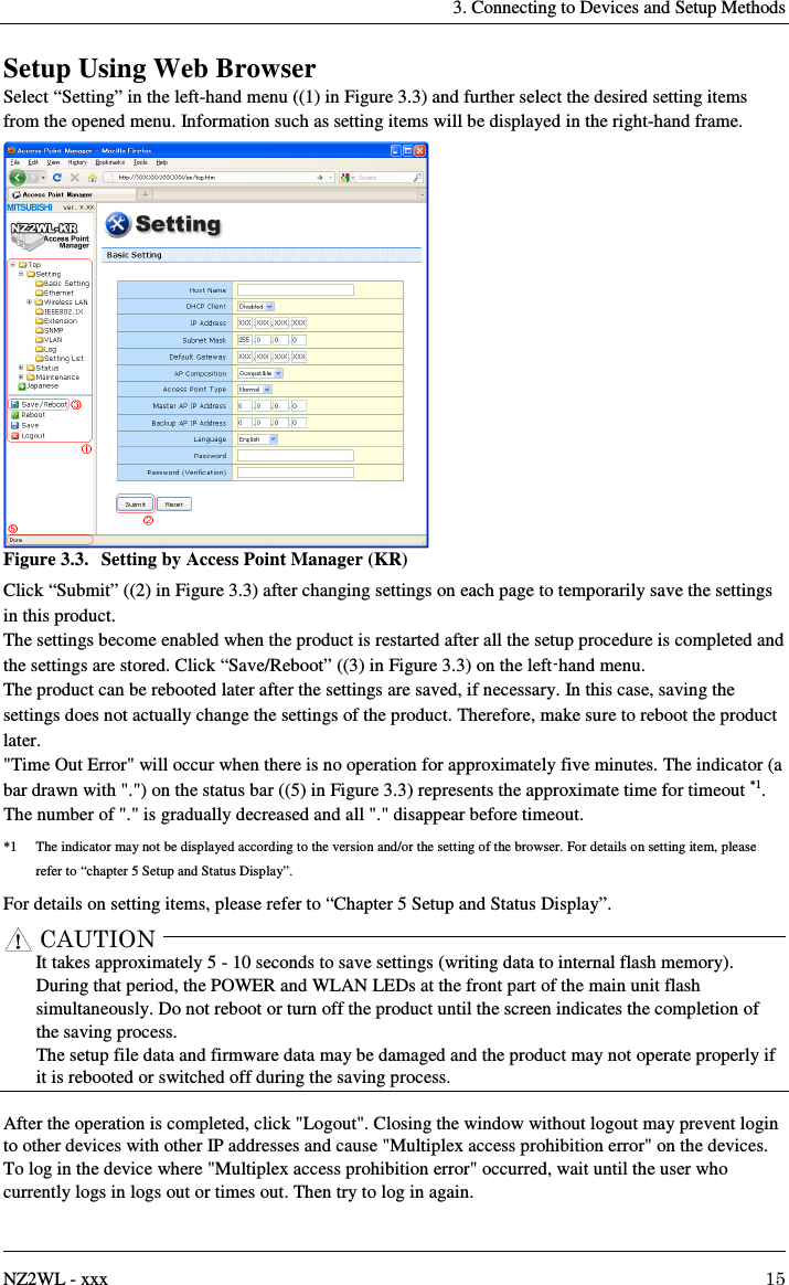
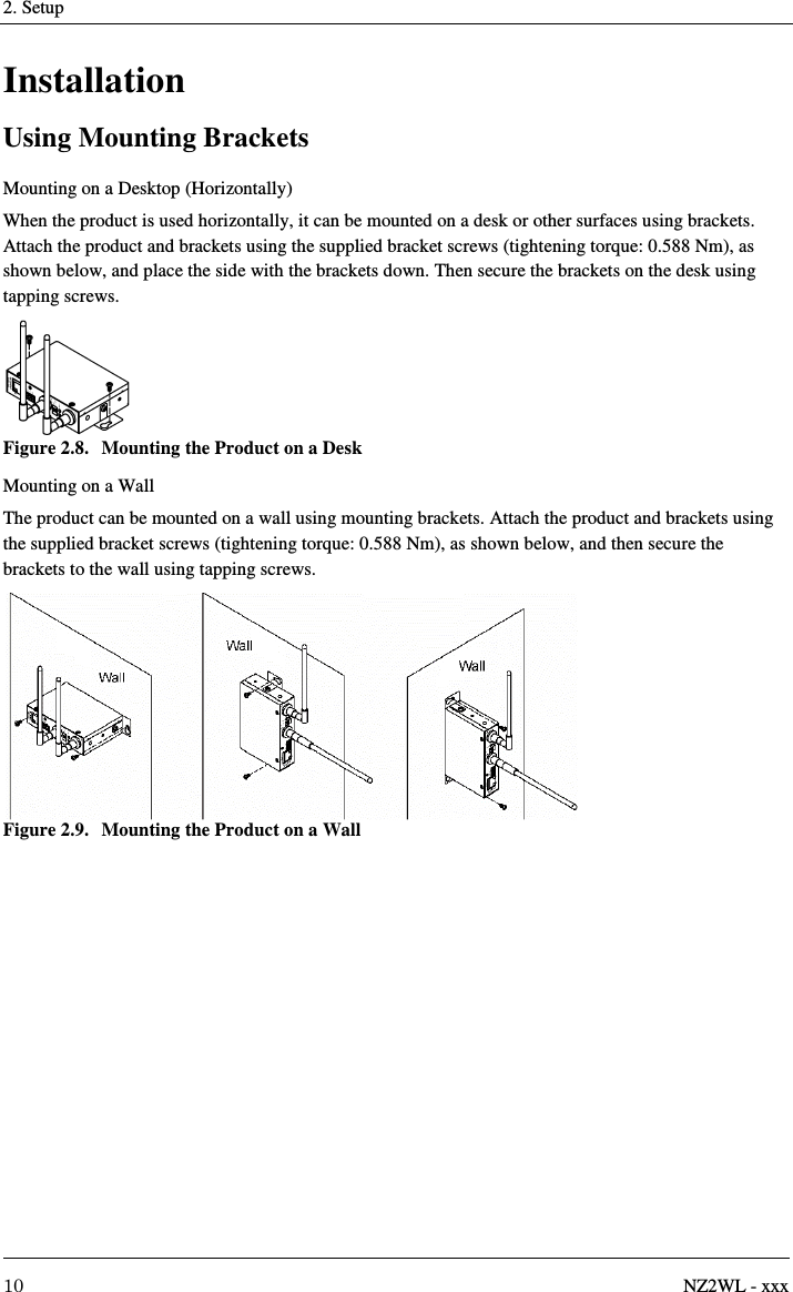
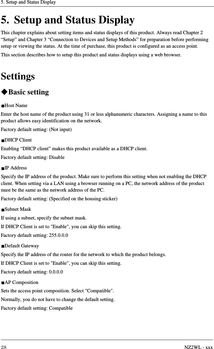
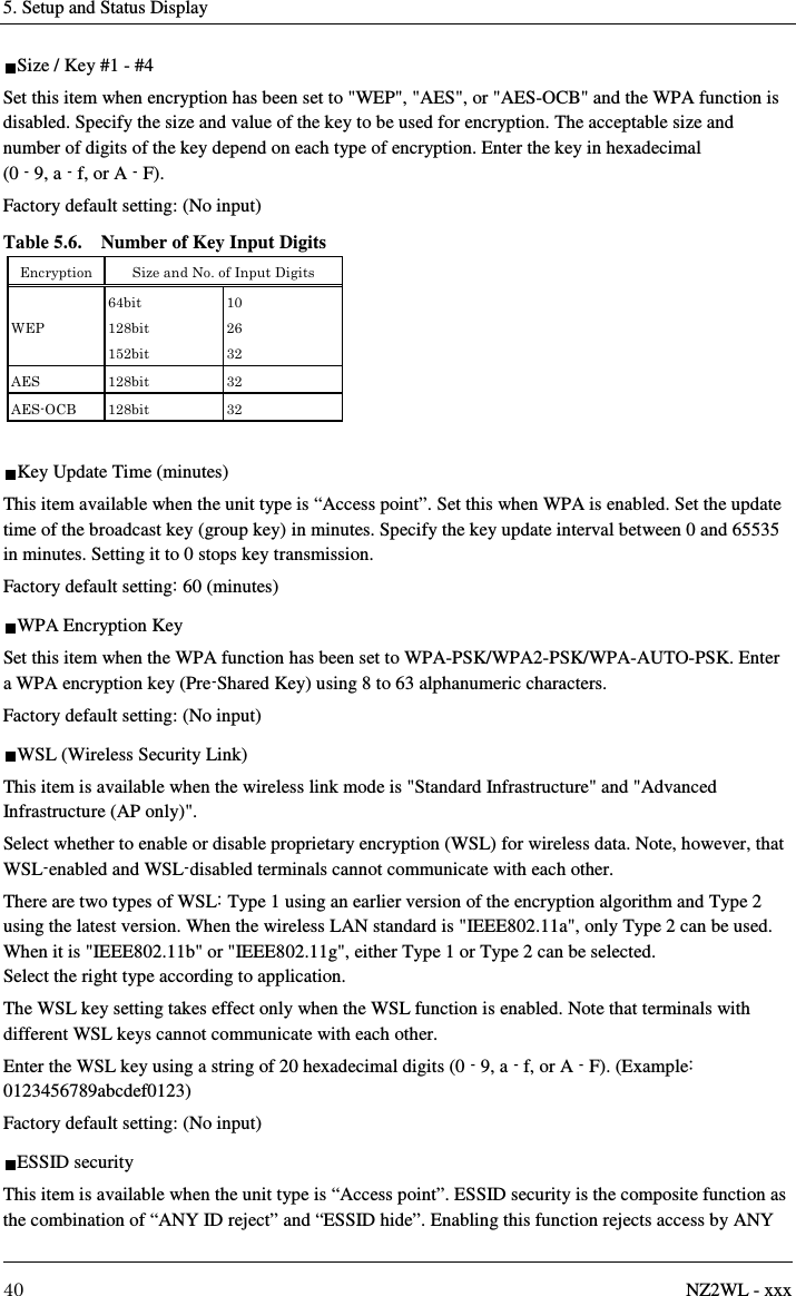
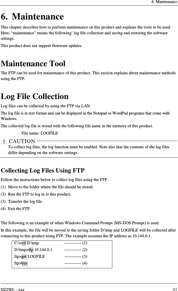
![3. Connecting to Devices and Setup Methods 16 NZ2WL - xxx Setup Using TELNET This section describes how to perform setup using TELNET. This procedure requires an application in which TELNET can be used. In Windows, “Command Prompt” can be used. Connecting to the Product Using TELNET Start up an application in which TELNET can be used (e.g. Command Prompt) and enter the IP address of this product after the telnet command*1. When connecting to this product using TELNET for the first time, enter the default IP address. For example, if the default IP address of the AP is [10.144.0.1], enter as follows. telnet 10.144.0.1 The following login window is displayed when connected to this product. If the login window is not displayed, the IP address setting for the personal computer may be incorrect. Figure 3.4. Login Window Enter the password on the login window and press "Enter" to log in. At the time of purchase, no password has been set up, so when connecting for the first time, just press "Enter". *1 The telnet command may not be initially available depending on the versions of Windows. For how to enable the telnet command, refer to the Windows help screen.](https://usermanual.wiki/Contec/NZ2WL-US.User-Manual/User-Guide-3025295-Page-30.png)
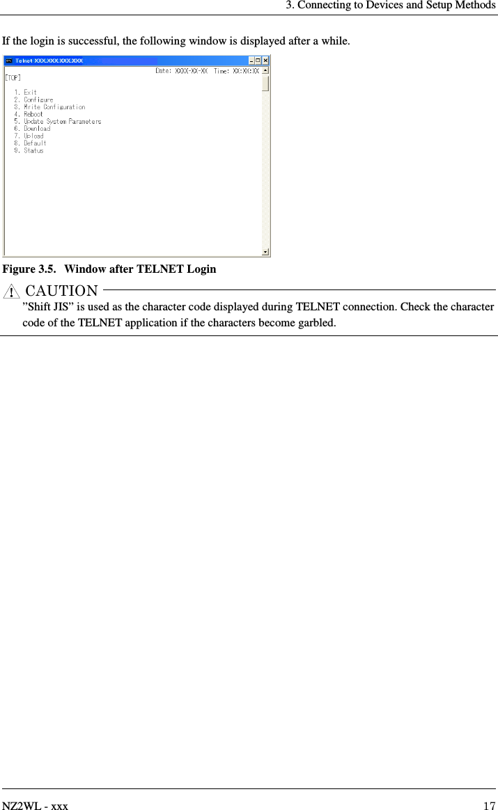
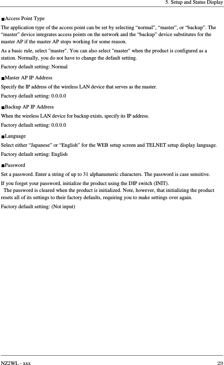
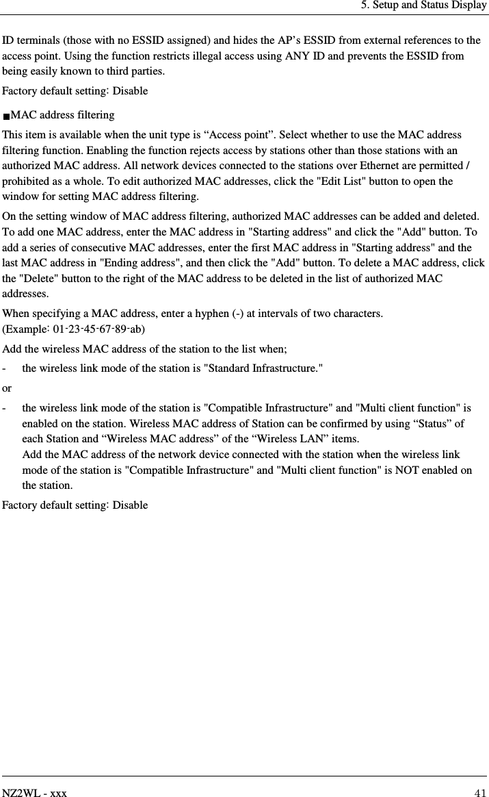
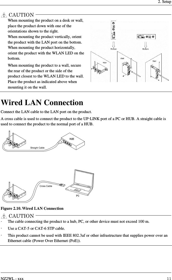
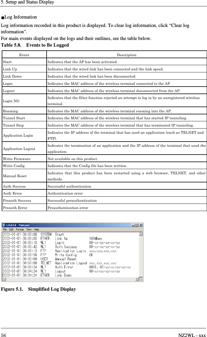
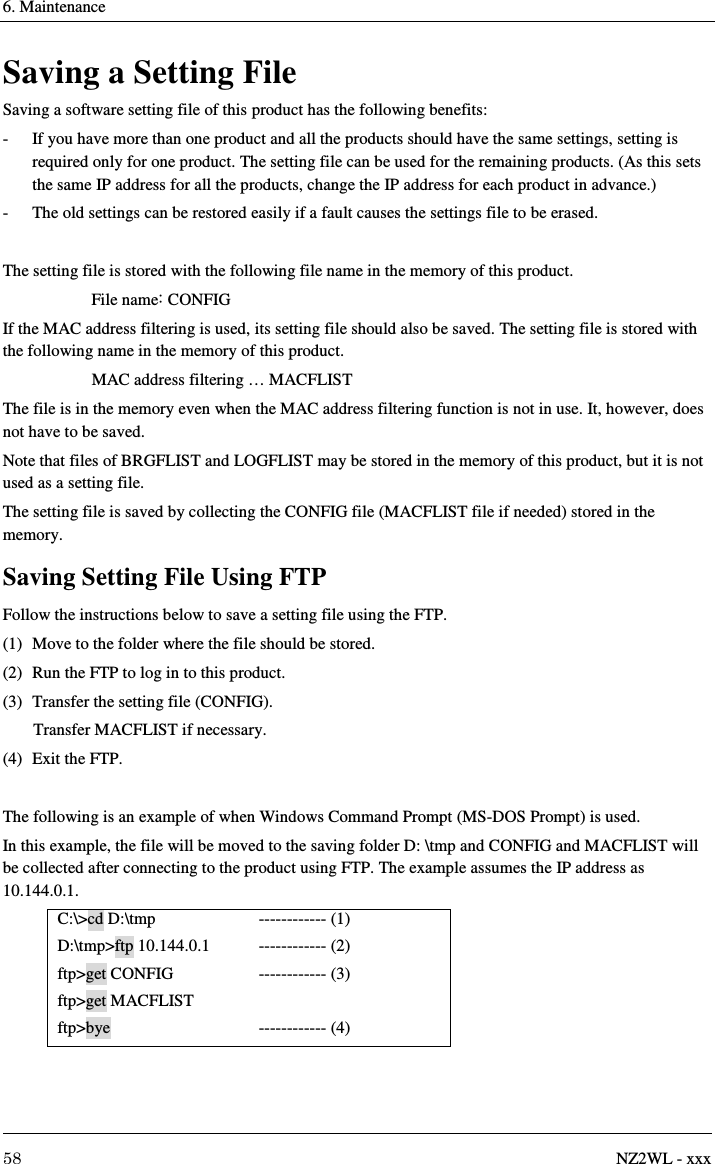
![5. Setup and Status Display 50 NZ2WL - xxx Detailed Setting You can select the types of events to be logged. Setting [Login], [Logout], [Login NG], [Roaming], [Tunnel Start], [Tunnel Stop], [Application Login], [Application Logout], [Auth Success / Error] and [Date / Time Set] to “ON” allows the selected events to be logged. Setting them to “OFF” prevents them from being logged. See Table 5.8 for a description of the types of events. Factory default setting: All "ON" Status Display A list of status information on this product can be displayed by selecting “Status” after logging in through a web browser or TELNET. This displays the following information. Basic Information - Loader Version Displays the version of this product's loader. - Firmware Version Displays the version of this product's firmware. - Hardware Version Displays the version of this product's hardware (circuit board). - Ethernet Address Displays the wired LAN (Ethernet) MAC address of the access point. - Wireless MAC Address Displays the MAC address of the wireless LAN card. - IP Address Displays the IP address of the access point. - Subnet Mask Displays the subnet mask set for the access point. The subnet mask is the mask value used when obtaining the network address of the subnet from the IP address. The subnet value can be obtained from the logical OR of the mask value and the IP address. - Default Gateway The gateway is a device that provides a relay between different networks. This displays the IP address of the standard connected gateway. - Country Identification Code Displays the country identification code of this product.](https://usermanual.wiki/Contec/NZ2WL-US.User-Manual/User-Guide-3025295-Page-64.png)
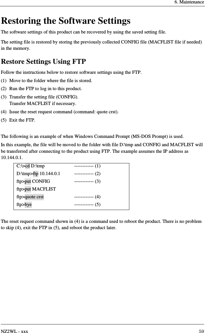
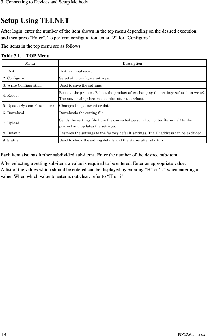
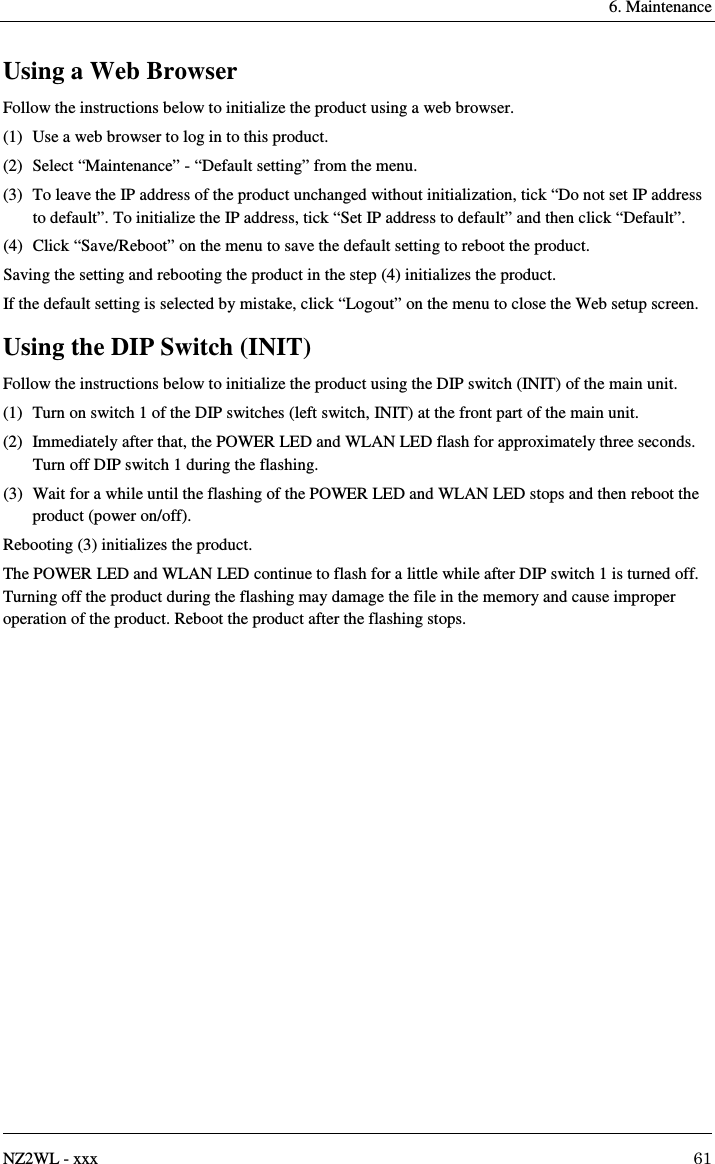
![6. Maintenance 60 NZ2WL - xxx Time Setting Set the time on this product. Enter the year (4 digits), month, day, time (24-hour notation), minute, and second, and then click the [Update] button. If you enter one digit for the month or day, a zero will be added to display the month or day in two digits. You can enter either one digit or two digits with an added zero. (Example: 2010/8/12 13:06:01) Clicking the [Set PC Time] button copies the time of the internal clock of the PC with the browser opened to the input form. Initialization There are three ways to initialize this product (recovering the factory default settings). - Using TELNET - Using a web browser - Using the DIP switch of the main unit (INIT) Each initialization method is described below. Using TELNET Follow the instructions below to initialize the product using TELNET. (1) Use TELNET to log in to this product. (2) In the main menu, select "8. Default". (3) Enter “Y” for the question “Load default setting? (Y/N)” (4) For the question “Load default IP address? (Y/N)”, enter “Y” to initialize the IP address as well or “N” to leave it unchanged. (5) From the main menu, select “4. Reboot” - “1. Cold boot”, and then enter “Y” for the question “Save the setting? (Y/N)”. Then reboot the product. Saving the setting and rebooting the product after loading the default setting initializes the product. If the default setting is loaded by mistake, select “1. Exit” from the main menu and enter “N” for the question “Save the setting? (Y/N)” without rebooting the product. This allows the setting to be unchanged and terminated.](https://usermanual.wiki/Contec/NZ2WL-US.User-Manual/User-Guide-3025295-Page-74.png)
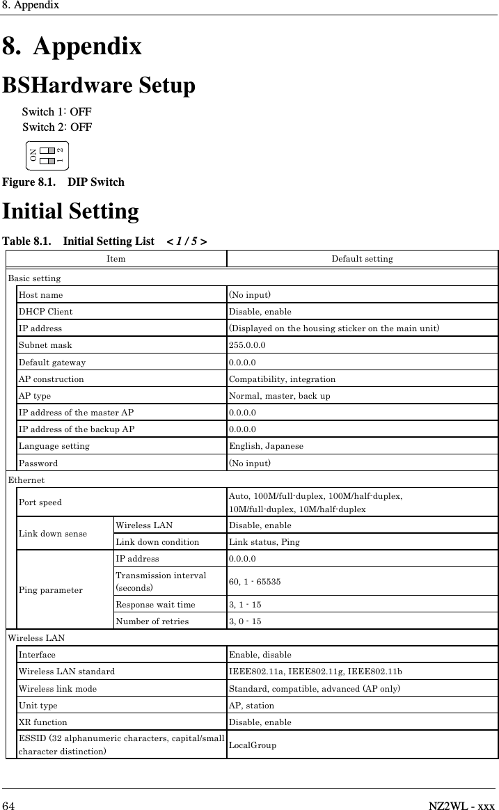
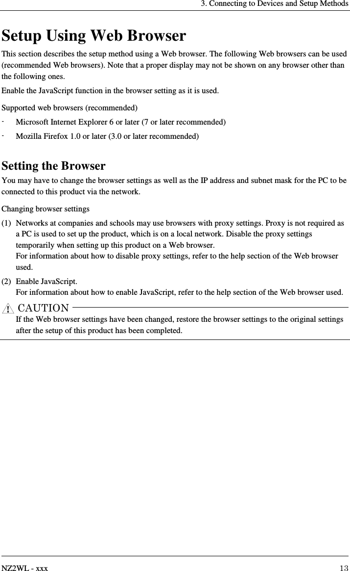
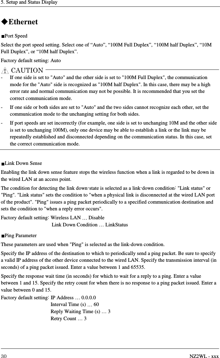
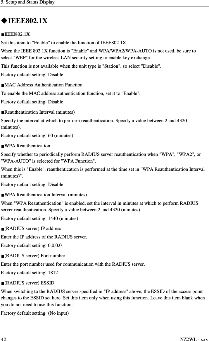
![8. Appendix NZ2WL - xxx 71 External Dimensions Figure 8.2. External Dimensions Figure 8.3. Antenna Dimensions (when installed with mounting brackets) Pin Layout of LAN Port Table 8.6. Pin Layout of LAN Port Pin No. Signal name 1 TX+ 2 TX- 3 RX+ 4 - 5 - 6 RX- 7 - 8 - 25.4 [mm]φ9.518103128.455φ10φ7SR3.410/100MLINKACT18](https://usermanual.wiki/Contec/NZ2WL-US.User-Manual/User-Guide-3025295-Page-85.png)
![72 NZ2WL - xxx WARRANTY Please confirm the following product warranty details before using this product. 1. Gratis Warranty Term and Gratis Warranty Range If any faults or defects (hereinafter "Failure") found to be the responsibility of Mitsubishi occurs during use of the product within the gratis warranty term, the product shall be repaired at no cost via the sales representative or Mitsubishi Service Company. However, if repairs are required onsite at domestic or overseas location, expenses to send an engineer will be solely at the customer’s discretion. Mitsubishi shall not be held responsible for any re-commissioning, maintenance, or testing on-site that involves replacement of the failed module. [Gratis Warranty Term] The gratis warranty term of the product shall be for one year after the date of purchase or delivery to a designated place. Note that after manufacture and shipment from Mitsubishi, the maximum distribution period shall be six (6) months, and the longest gratis warranty term after manufacturing shall be eighteen (18) months. The gratis warranty term of repair parts shall not exceed the gratis warranty term before repairs. [Gratis Warranty Range] (1) The range shall be limited to normal use within the usage state, usage methods and usage environment, etc., which follow the conditions and precautions, etc., given in the instruction manual, user's manual and caution labels on the product. (2) Even within the gratis warranty term, repairs shall be charged for in the following cases. 1. Failure occurring from inappropriate storage or handling, carelessness or negligence by the user. Failure caused by the user's hardware or software design. 2. Failure caused by unapproved modifications, etc., to the product by the user. 3. When the Mitsubishi product is assembled into a user's device, Failure that could have been avoided if functions or structures, judged as necessary in the legal safety measures the user's device is subject to or as necessary by industry standards, had been provided. 4. Failure that could have been avoided if consumable parts designated in the instruction manual had been correctly serviced or replaced. 5. Failure caused by external irresistible forces such as fires or abnormal voltages, and Failure caused by force majeure such as earthquakes, lightning, wind and water damage. 6. Failure caused by reasons unpredictable by scientific technology standards at time of shipment from Mitsubishi. 7. Any other failure found not to be the responsibility of Mitsubishi or that admitted not to be so by the user.](https://usermanual.wiki/Contec/NZ2WL-US.User-Manual/User-Guide-3025295-Page-86.png)