Continental Automotive Systems GNAD1A GSM/GPRS/EGPRS 850/1900 Module User Manual GNAD1A GSM module user guide v5 FCC
Continental Automotive Systems, Inc. GSM/GPRS/EGPRS 850/1900 Module GNAD1A GSM module user guide v5 FCC
User Manual

PREPARED BY:
Irina Shmagin
DOCUMENT
NUMBER:
APPROVALS: REVISION: 5.0
DATE: 07/14/2008
PAGE 1 OF 8
PROPRIETARY INFORMATION
NO DISSEMINATION OR USE ALLOWED
DOCUMENT TYPE
Users Manual
WITHOUT PRIOR WRITTEN PERMISSION
User’s Guide for GNAD1A GSM Module

Document No.:
Error! Reference source not
found.
Title: User Guide for GNAD1A GSM module
Continental Automotive Systems
Date: 07/14/2008
Page: 2
1.
INTRODUCTION................................................................................................................................. 3
1.1
D
OCUMENT CHANGES
.......................................................................................................................... 3
2.
OVERVIEW ......................................................................................................................................... 3
2.1
G
ENERAL
........................................................................................................................................... 3
2.2
GNAD1A
D
ESCRIPTION
....................................................................................................................... 3
2.3
T
EST
S
ET
-
UP
D
ESCRIPTION
................................................................................................................... 4
2.4
Q
UICK
S
TART
C
OMMUNICATION
G
UIDE
................................................................................................. 5
2.5
Q
UICK
S
TART
C
ALL
G
UIDE
................................................................................................................... 5
2.6
L
IST OF
S
UPPORTED
AT
COMMANDS FOR TESTING PURPOSES
................................................................... 6
2.7
FCC
N
OTE
.......................................................................................................................................... 8
2.8
C
ERTIFICATION
T
ESTING
G
UIDE
............................................................................................................ 9
2.8.1
Smart Card Features (SIM ME)....................................................................................................... 9
2.8.2
EONS Test Cases............................................................................................................................ 9
2.8.3
Call Processing............................................................................................................................ 10
2.8.4
Network Selection......................................................................................................................... 10
2.8.5
UICC-OTA for MSISDN update..................................................................................................... 10
2.8.6
Enhanced Network Selection (ENS) ............................................................................................... 10
TABLE OF FIGURES:
Figure 1: Diagram of GNAD1A GSM Module _______________________________________________________4
Figure 2: Photograph of GNAD1A GSM Module ____________________________________________________4
Figure 3. Assembled test set-up for GMAD1A functional testing ________________________________________5
Document No.:
Error! Reference source not
found.
Title: User Guide for GNAD1A GSM module
Continental Automotive Systems
Date: 07/14/2008
Page: 3
1. Introduction
1.1 Document changes
Revision Description Date
1.0 Initial draft 1/30/07
2.0 Updated Version 04/29/2008
5.0 Updated Version 07/14/2008
2. Overview
2.1 General
GNAD1A is a proprietary GSM/GPRS/EDGE module from Continental Automotive Systems.
The module will be integrated into telecommunication control devices produced by Continental
for its automotive customers.
The GAND1A test set-up is available for third-party testing which do not require audio or data-
logging capabilities. This document will provide description for the test set-up.
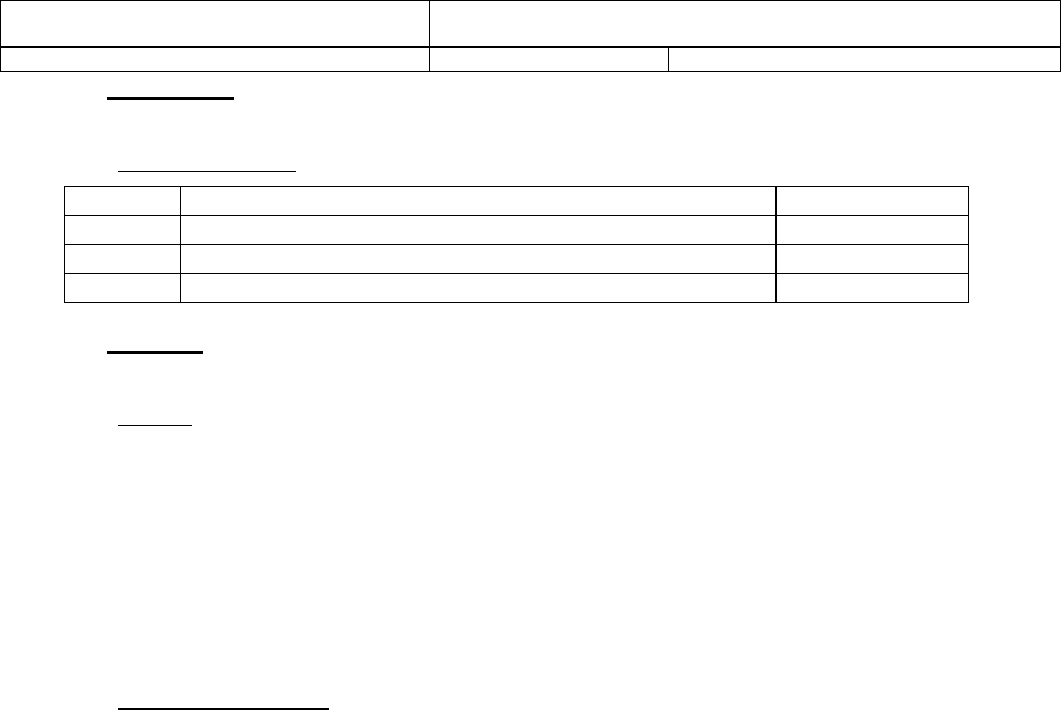
2.2 GNAD1A Description
GNAD1A is a proprietary GSM module designed and manufactured by Continental Automotive
Systems for use in automotive applications. The key features of the modules are:
• Quad-band GSM/GPRS/EDGE
• GPRS and EDGE Class 10
• 5 V DC Input
• 250-450 mA average current draw while in a call
• Up to 3 A peak current during GSM burst
• Fakra RF connectors
• Primary (black) and Secondary (maroon) RF antenna connectors
• On-board SIM card connector for 3 V SIM cards
• 40-pin system-level connector
• PCM audio
• Primary UART with auto baud rate detection up to 115.2 Kbps. Max supported rate is
921.6 Kbps.
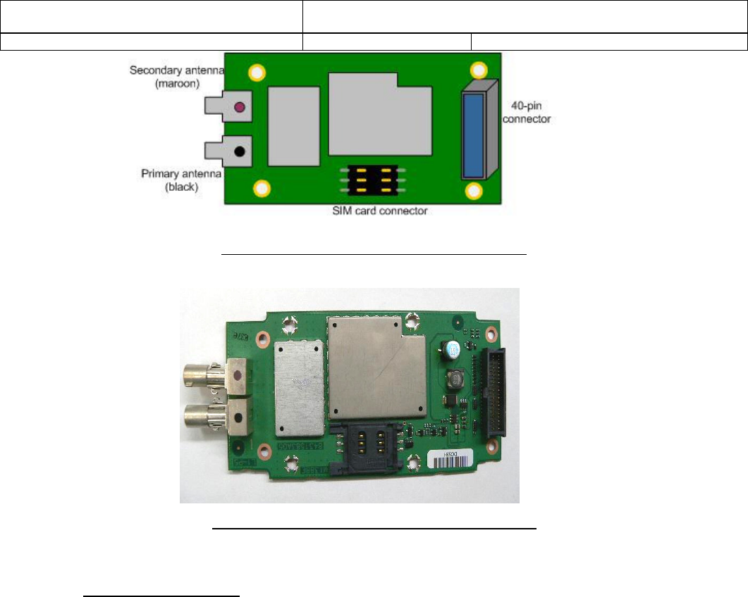
A diagram of the GNAD1A GSM module is shown in Figure 1. A photograph of the GNAD1A
module is shown in Figure 2.
Document No.:
Error! Reference source not
found.
Title: User Guide for GNAD1A GSM module
Continental Automotive Systems
Date: 07/14/2008
Page: 4
Figure 1: Diagram of GNAD1A GSM Module
Figure 2: Photograph of GNAD1A GSM Module
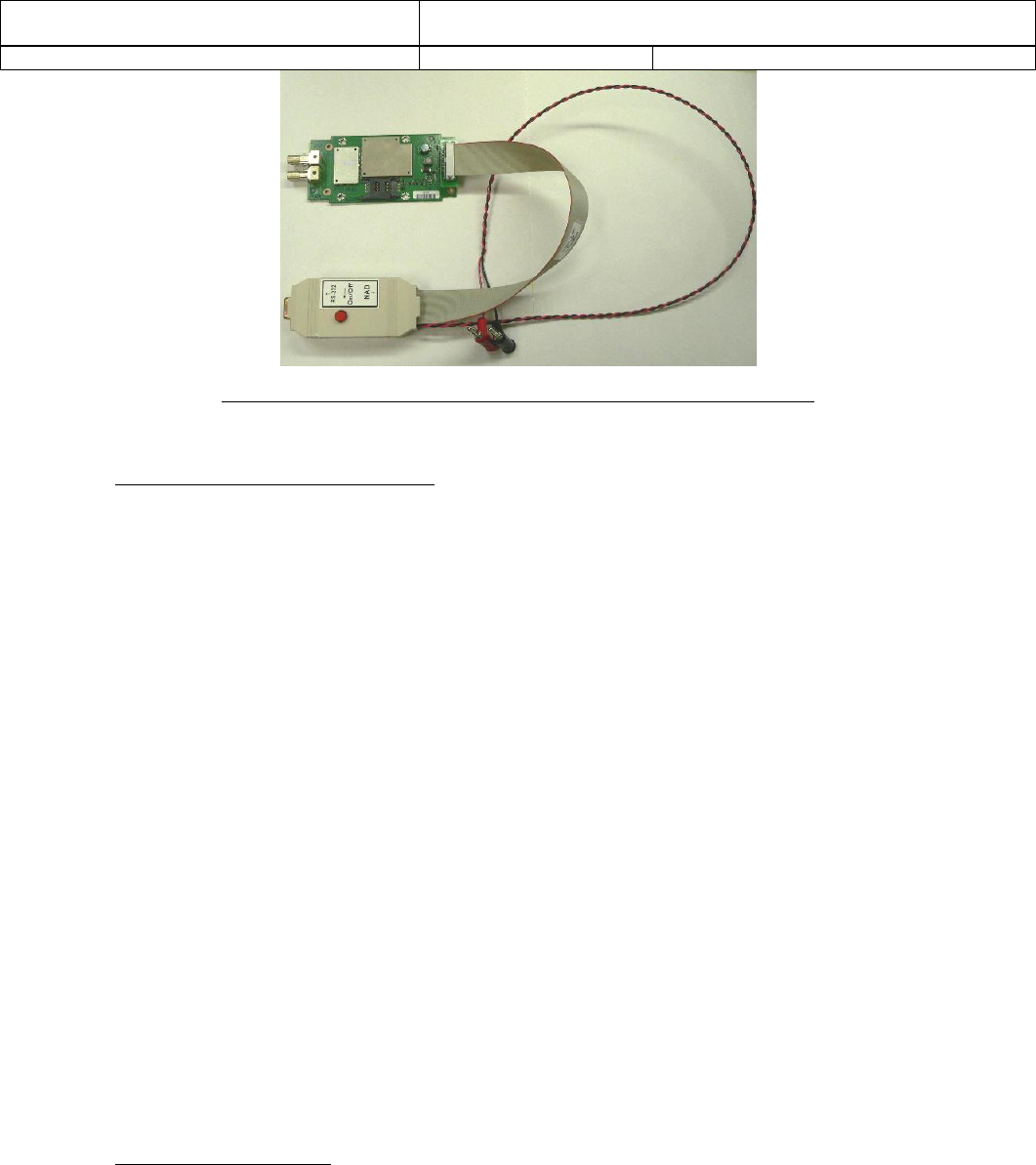
2.3 Test Set-up Description
This set-up includes:
- 5V Battery Input Connector
- 40 pin connector to connect to GNAD1A
- On/Off Bounce Button for NAD_ON_OFF power
- RS232 communication with the primary UART (default baud rate 57.6Kbits)
- On-OFF Switch
- AT commands control
An assembled test set-up is shown in Figure 3:
5V,UARTs,
PCM audio etc.
Document No.:
Error! Reference source not
found.
Title: User Guide for GNAD1A GSM module
Continental Automotive Systems
Date: 07/14/2008
Page: 5
Figure 3. Assembled test set-up for GMAD1A functional testing
2.4 Quick Start Communication Guide
In order to communicate from a laptop to the GNAD1A (as shown in Figure 3), the
following equipment is needed:
Laptop PC
Interface board
5V DC Power supply (2 Amp)
GNAD1A
Serial Port Cable
HyperTerminal, Hyper Access or another Communication tool For use with
HyperTerminal baud rate needs to be set to 57.6Kbits, 8 bits, no parity, no stop bits,
and hardware flow control.
The following procedure should be followed to communicate with the GNAD1A:
1) Set the power supply to 5.0V and the current limit to 2.0A.
2) Connect the interface board to the power supply
3) Connect the serial port cable to the COM1 of PC and to the RS-232 connection on
the Interface board.
4) Turn on the power supply output.
5) Press the NAD_ON_OFF switch for 3 seconds. The module should power on.
6) Use the primary UART to communicate with the NAD using HyperTerminal,
Hyperaccess etc. “READY” message will appear when module powers on.
7) To turn the NAD off, press and hold the NAD_ON_OFF switch again for 2 seconds.
2.5 Quick Start Call Guide
After setting up the interface board and GNAD1A as discussed in 2.4, the following AT
commands can be sent to the NAD using HyperTerminal to make a call:
1) Type AT to confirm communication should receive OK back.(optional)

Document No.:
Error! Reference source not
found.
Title: User Guide for GNAD1A GSM module
Continental Automotive Systems
Date: 07/14/2008
Page: 6
2) The module is pre-set to use primary (black) antenna. Type AT+TASW= 1
(primary) or AT+TASW=2 (secondary) for antenna selection.
3) The radio will start scanning automatically on power-up with an unlocked SIM.
4) Type AT+XBANDSEL=NUM (where NUM is 850, 900, 1800, 1900 or 0 for all
bands) to set the band of operation if desired (optional).
5) Type ATD123456; to make a voice call.
6) To end the call type ATH
Data calls are not discussed here but standard AT commands apply.
2.6 List of Supported AT commands for testing purposes
The section lists AT commands supported by GNAD1A. Unless otherwise noted, the AT
commands shall follow the syntaxes specified in GSM 07.07. See AT Command manual for
more information.
AT COMMAND FUNCTION
+CACM Accumulated Call Meter
+CAMM Accumulated Call Meter Maximum
+CAOC Advice of Charge
+CBM Cell Broadcast Message Receipt
+CBST Selecting Bearer Service Type
+CCFC Call Forwarding
+CCLK System Date and Time
+CCWA Call Waiting
+CDSI SMS Status Report Receipt
+CEER Extended Error Report
+CGACT PDP Context Activate or Deactivate
+CGATT GPRS Attach or Detach
+CGDCONT Define PDP Context
+CGEREP GPRS Event Reporting
+CGMI Request Manufacturer ID
+CGMM Request Model ID
+CGMR Request Revision
+CGQMIN Quality of Service (Minimum Accepted)
+CGQREQ Quality of Service (Requested)
+CGREG GPRS Network Registration Status
+CGSN Request Serial Number
+CHLD Supplementary Call Control
+CHUP Hang up Call
+CIEV Event Notifications
+CIMI Request IMSI
+CIND Indicator Control

Document No.:
Error! Reference source not
found.
Title: User Guide for GNAD1A GSM module
Continental Automotive Systems
Date: 07/14/2008
Page: 7
+CLAN Set Language
+CLCC List Current Calls
+CLCK Facility Lock
+CLIP Calling Line Identification (Caller ID)
+CLIR Calling Line Identification Restriction
+CME ERROR Extended Error Report
+CMEE Extended Error Reporting
+CMER Event Reporting
+CMGD Delete SMS Message
+CMGF Message Format
+CMGL List SMS Messages
+CMGR Read SMS Messages
+CMGS Send SMS Message
+CMGW Write Message to Memory
+CMS ERROR SMS Message Service Failure Result
Code
+CMSS Send Message from Storage
+CMTI SMS Message Receipt
+CMUX GSM07.10 Multiplexer
+CNMI New Message Indications
+CNUM Request MSIDSN
+COLP Connected Line Identification
+COPS Operator Selection
+CPBF Find Phonebook Entry
+CPBR Read Phonebook
+CPBS Phonebook Select
+CPBW Write and Delete Phonebook Entry
+CPIN SIM PIN Control
+CPMS Preferred Message Storage
+CPOL Preferred Operator List
+CPWD Change Password
+CRC Cellular Result Code
+CREG Network Registration
+CRING Incoming Call Notification
+CRSM Request SIM Information
+CSCA Service Center Address
+CSCB Select Cell Broadcast Message Types
+CSCS Set/Request Character Set
+CSDH Text Mode Parameters
+CSMS Select Message Service
+CSQ Signal Quality
+GMI Request Manufacturer ID
+GMM Request Model ID
Document No.:
Error! Reference source not
found.
Title: User Guide for GNAD1A GSM module
Continental Automotive Systems
Date: 07/14/2008
Page: 8
+GMR Request Revision
+IPR Baud Rate (Persistent)
+VTD Default DTMF Tone Duration
+VTS Send DTMF Tone
&F Return to Factory Default
A Answer Incoming Call
CONNECT Connection Notification
D Dial
H Hang up Call
NO CARRIER Connection Failure Notification
O Switch to Online Data Mode
RING Incoming Call Notification
S0 Automatic Answer
S7 Connection Completion Timeout
Telematics Specific Commands
AT COMMAND FUNCTION
READY NAD Power Up Unsolicited Response
+CBAUD Baud Rate (Temporary)
+TADIAG Antenna Diagnostics
+TASW Antenna Switch
+TPIN Remaining SIM PIN/PUK Attempts
READY Power Up Unsolicited Response
2.7 FCC Note
This device complies with Part 15 of the FCC Rules. The FCC ID for this device is
LHJGNAD1A. Operation is subject to the following two conditions:
1. This device may not cause harmful interference.
2. This device must accept any interference received, including interference that may
cause undesired operation.
Changes or modifications to this system by other than an authorized service facility could void
authorization to use this equipment.
Please note that if the GNAD1A module is integrated into a host device, second label must be
placed on the outside of the final device that contains the following text: "Contains FCC ID:
LHJGNAD1A".
The GNAD1A module is offered for use with an external antenna which is not specified by
Continental Automotive Systems. The intended use-case for the device is with a vehicle roof-top
antenna. The antenna(s) which are used for the transmitter must be installed to provide a
separation distance of at least 20cm from all persons and must not be co-located or operating in

Document No.:
Error! Reference source not
found.
Title: User Guide for GNAD1A GSM module
Continental Automotive Systems
Date: 07/14/2008
Page: 9
conjunction with any other antenna or transmitter. The following are the guidelines for the
maximum antenna gain which should be used for selecting an external antenna:
• For the 850 MHz band the maximum antenna gain is -1.24 dBd
• For the 1900 MHz band the maximum antenna gain is 7.8 dBi
The maximum gain of the antenna path (cable loss + antenna gain) shall not exceed the above
mentioned values.
2.8 Certification Testing Guide
This section is designed to provide specific command to be used during certification testing.
2.8.1 Smart Card Features (SIM ME)
• Verify Deletion of a Smart Card Based Contact
Use AT+CPBS to select directory and AT+CPBW=6,"",,"" to delete location.
• Verify the terminal supports calling from the smart card contacts list.
Use ATD>#; (#) is preset number.
• Verify Deletion of an FDN entry
Use AT+CPBW=6,"",,"" to delete location.
• Verify Allowed MO Calls
Makes calls, No pause dialing and no spaces
• Verify Disallowed MO Calls
Use AT+CEER to get message that says "CC setup error,279,FDNfailed"
• Verify Disallowed Calling from the Smart Card Contact List, LND and SDN Phonebooks
AT+CEER to get message that says "CC setup error,279,FDNfailed"
• Verify PIN1 Changing Procedure
Use Command AT+CPWD=<fac>,<oldpwd>,<newpwd>
• Verify PIN1 Blocking Behavior at Power Up
Use AT+XPINCNT gives count of attemps left on each Pin
• Verify PIN2 Changing Procedure
Use AT+CPWD="P2","<old pin2>","<new pin2>"
• Verify Display of Initial MSISDNs
Use AT+CNUM
2.8.2 EONS Test Cases

Document No.:
Error! Reference source not
found.
Title: User Guide for GNAD1A GSM module
Continental Automotive Systems
Date: 07/14/2008
Page: 10
• Manual Selection
Use AT+COPS for manual selection
• Display Extended Operator Name
Use AT+XCOPS=8 for short Operator Name
Use AT+XCOPS=9 for long Operator Name
Use AT+XEONS=9 for EONS long Name
2.8.3 Call Processing
• Pause dialing is not supported per compliance matrix
2.8.4 Network Selection
• Use AT+COPS=0 to set up automatic scaning
• Use AT+COPS=? To display NW information
• Test for limited service:
AT+CREG=1 (in the beginning)
+CREG: 3 (=> registration denied when Reject by NW is done => limited service)
AT+XCOPS=9
+CME ERROR: operation not supported (display NW name in case of registration)
2.8.5 UICC-OTA for MSISDN update
• Use AT+CFUN=6 at power up
• Use AT+CNUM to check the MSISDN
2.8.6 Enhanced Network Selection (ENS)
• Use AT+CFUN=6 at power up
• +STKPRO: 01,1,1,"3F007F206F31" will be received on the Hypoterminal upon
Refresh
• Use AT+STKTR=01,0,255 to complete Refresh
• Repeat the AT+STKTR=01,0,255 in respinse to each +STKPRO unsolicited message