Continental Automotive Systems HIIBU Smart Key ECU User Manual Spezifikationsformular in Deutsch mit Struktur
Continental Automotive Systems Corporation Smart Key ECU Spezifikationsformular in Deutsch mit Struktur
Users Manual
.
Proprietary data, company confidential. All rights reserved.
Confié à titre de secret d'entreprise. Tous droits réservés.
Comunicado como segredo empresarial. Reservados todos os direitos.
Confidado como secreto industrial. Nos reservamos todos los derechos.
.
.
Weitergabe sowie Vervielfältigung dieser Unterlage, Ver-
wertung und Mitteilung ihres Inhalts nicht gestattet, soweit
nicht ausdrücklich zugestanden. Zuwiderhandlungen ver-
pflichten zu Schadenersatz. Alle Rechte vorbehalten, insbe-
sondere für den Fall der Patenterteilung oder GM-Eintragung.
.
Identification No. :
Document : User Manual for HI IBU
Project : HI IBU
Project Code :
Version: 0.1
Date: May 18, 2015
Engineering change order-No.:
Design Freeze No.:
Number of pages: 12
Filename: User Manual for HI IBU_ENG.doc

Editor :
J. Heo
Document name
Project code
Version:
0.1
May, 18, 2015
ECO / DF No.
Identification No. : Document No.
File:
User Manual for HI IBU_ENG
Page 2 / 13
.
Proprietary data, company confidential. All rights reserved.
Confié à titre de secret d'entreprise. Tous droits réservés.
Comunicado como segredo empresarial. Reservados todos os direitos.
Confidado como secreto industrial. Nos reservamos todos los derechos.
.
.
Weitergabe sowie Vervielfältigung dieser Unterlage, Ver-
wertung und Mitteilung ihres Inhalts nicht gestattet, soweit
nicht ausdrücklich zugestanden. Zuwiderhandlungen ver-
pflichten zu Schadenersatz. Alle Rechte vorbehalten, insbe-
sondere für den Fall der Patenterteilung oder GM-Eintragung.
.
Contents list Page
1. System configulation 3
1.1 Scope of HI IBU System 3
1.1.1 Smart key system offer following feature 3
1.1.2 BCM functions offer following feature 3
1.1.3 TPMS receiver functions offer following feature 3
1.2 short description of the SYSTEM 3
1.2.1 General Definition of IBU 3
1.2.2 Wireless Communication 4
1.2.3 concept Description 4
1.2.4 System Architecture 4
1.2.5 Main Functions 5
2.3 HI IBU ECU 12

Editor :
J. Heo
Document name
Project code
Version:
0.1
May, 18, 2015
ECO / DF No.
Identification No. : Document No.
File:
User Manual for HI IBU_ENG
Page 3 / 13
.
Proprietary data, company confidential. All rights reserved.
Confié à titre de secret d'entreprise. Tous droits réservés.
Comunicado como segredo empresarial. Reservados todos os direitos.
Confidado como secreto industrial. Nos reservamos todos los derechos.
.
.
Weitergabe sowie Vervielfältigung dieser Unterlage, Ver-
wertung und Mitteilung ihres Inhalts nicht gestattet, soweit
nicht ausdrücklich zugestanden. Zuwiderhandlungen ver-
pflichten zu Schadenersatz. Alle Rechte vorbehalten, insbe-
sondere für den Fall der Patenterteilung oder GM-Eintragung.
.
1. System configulation
1.1 Scope of HI IBU System
IBU(Integrated Body control unit) integrate BCM, Smart Key system and TPMS receiver in
one ECU
1.1.1 Smart key system offer following feature
passive access to two doors and trunk; driver side, passenger side, and trunk/tailgate
passive start after interior detection of the SMART KEY FOB.
LF-RF communication (based on Continental’s SMART KEY system)
passive access/locking of the two front doors via a toggle push button in the door
handles
passive access trunk/tailgate via the trunk lid switch at the trunk
immobilizer backup solution integrated into IBU
communication to the engine management system via a single line interface
communication to the ESCL via a single line interface
block of the steering column by the ESCL device
1.1.2 BCM functions offer following feature
BCM functions are for user convenience and warning for user safety
BCM functions directly or indirectrly control Lamps, Indicators, Rear curtain, Steering
wheel heat and relay
BCM function s receive inputs by wire or communication (CAN, LIN)
1.1.3 TPMS receiver functions offer following feature
Process receive data from TPMS sensor
Do display or warning according to received TPMS sensor data
1.2 short description of the SYSTEM
1.2.1 General Definition of IBU
The SMART KEY system is a system that allows the user to access and operate a
vehicle in a very convenient way.
The SMART KEY system is triggered by pressing a push button in the door handle
or by pressing a start-stop button in the dash board.
After triggered, the vehicle sends out a LF telegram to all antenna output. And then
Smartkey FOB measures the power of each antenna, and sends this information to
SMARTKEY UNIT(IBU). From this information, Smart Key unit determines the
location of SMART KEY FOB and decides whether to perform a particular action
(unlocking, locking…) or to remain inactive.

Editor :
J. Heo
Document name
Project code
Version:
0.1
May, 18, 2015
ECO / DF No.
Identification No. : Document No.
File:
User Manual for HI IBU_ENG
Page 4 / 13
.
Proprietary data, company confidential. All rights reserved.
Confié à titre de secret d'entreprise. Tous droits réservés.
Comunicado como segredo empresarial. Reservados todos os direitos.
Confidado como secreto industrial. Nos reservamos todos los derechos.
.
.
Weitergabe sowie Vervielfältigung dieser Unterlage, Ver-
wertung und Mitteilung ihres Inhalts nicht gestattet, soweit
nicht ausdrücklich zugestanden. Zuwiderhandlungen ver-
pflichten zu Schadenersatz. Alle Rechte vorbehalten, insbe-
sondere für den Fall der Patenterteilung oder GM-Eintragung.
.
1.2.2 Wireless Communication
Electromagnetic waves are used to exchange information between the vehicle and the
SMART KEY FOB. Both, vehicle and SMART KEY FOB are equipped with a transmitter,
a receiver and several antennas.
1.2.3 concept Description
With this concept it is possible to have a set of interior antennas that cover the vehicle’s
interior and a set of exterior antennas that cover the vehicle’s exterior.
For an unambiguous separation between the vehicle’s interior and exterior it is sufficient
that at least one area is covered exactly by the corresponding operating ranges of the
antennas.
The functions of the SMART KEY system have to be provided in a clearly defined and
limited range. For the up-link from the vehicle to the SMART KEY FOB, a magnetic field
with a frequency of 125 kHz and ASK modulation is used.
Technical aspects of 125 kHz – magnetic field:
virtually no reflections,
cubical decrease of field strength allows good range control,
released frequency band (ISM),
high penetration,
low quiescent current demand due to 125 kHz input stage (SMART KEY FOB),
less sensitive for detuning compared to higher frequency.
For the down-link from the SMART KEY FOB to the vehicle, the standard radio frequency
(RF) is used (similar to the classic remote control functions) with FSK modulation.
1.2.4 System Architecture
The system is designed as an optional system, making it possible to equip vehicles of the
same car-Line with different levels of access control systems.
The system is suitable to be integrated into an existing architecture that provides central
locking functions with standard remote control. This proposal assumes that the following
functions / devices are already present in the vehicle’s architecture.
Central locking system (latch / motor – drivers etc.)
Standard body control functions
Warning buzzer
Indicators
Lamps
Wiper control system
TPMS warnging and display
Convenience equipments
Editor :
J. Heo
Document name
Project code
Version:
0.1
May, 18, 2015
ECO / DF No.
Identification No. : Document No.
File:
User Manual for HI IBU_ENG
Page 5 / 13
.
Proprietary data, company confidential. All rights reserved.
Confié à titre de secret d'entreprise. Tous droits réservés.
Comunicado como segredo empresarial. Reservados todos os direitos.
Confidado como secreto industrial. Nos reservamos todos los derechos.
.
.
Weitergabe sowie Vervielfältigung dieser Unterlage, Ver-
wertung und Mitteilung ihres Inhalts nicht gestattet, soweit
nicht ausdrücklich zugestanden. Zuwiderhandlungen ver-
pflichten zu Schadenersatz. Alle Rechte vorbehalten, insbe-
sondere für den Fall der Patenterteilung oder GM-Eintragung.
.
1.2.5 Main Functions
The system allows the user to access and exit (unlock and lock) the vehicle without
performing any actions with the SMART KEY FOB.
The system allows the user to control ESCL lock/unlock, to operate relaies to provide
power(Off, Accessory, Ignition) to other ECU, and to start/stop the vehicle’s engine
without performing any actions with the SMART KEY FOB.
Additionally, the system offers the user can operate all vehicle functions by contacting
the Fob to the Start/stop button, which have Immobilizer antenna(terminal control
fuction), and by inserting the mechanical key blade into the door handle(Passive
access function).
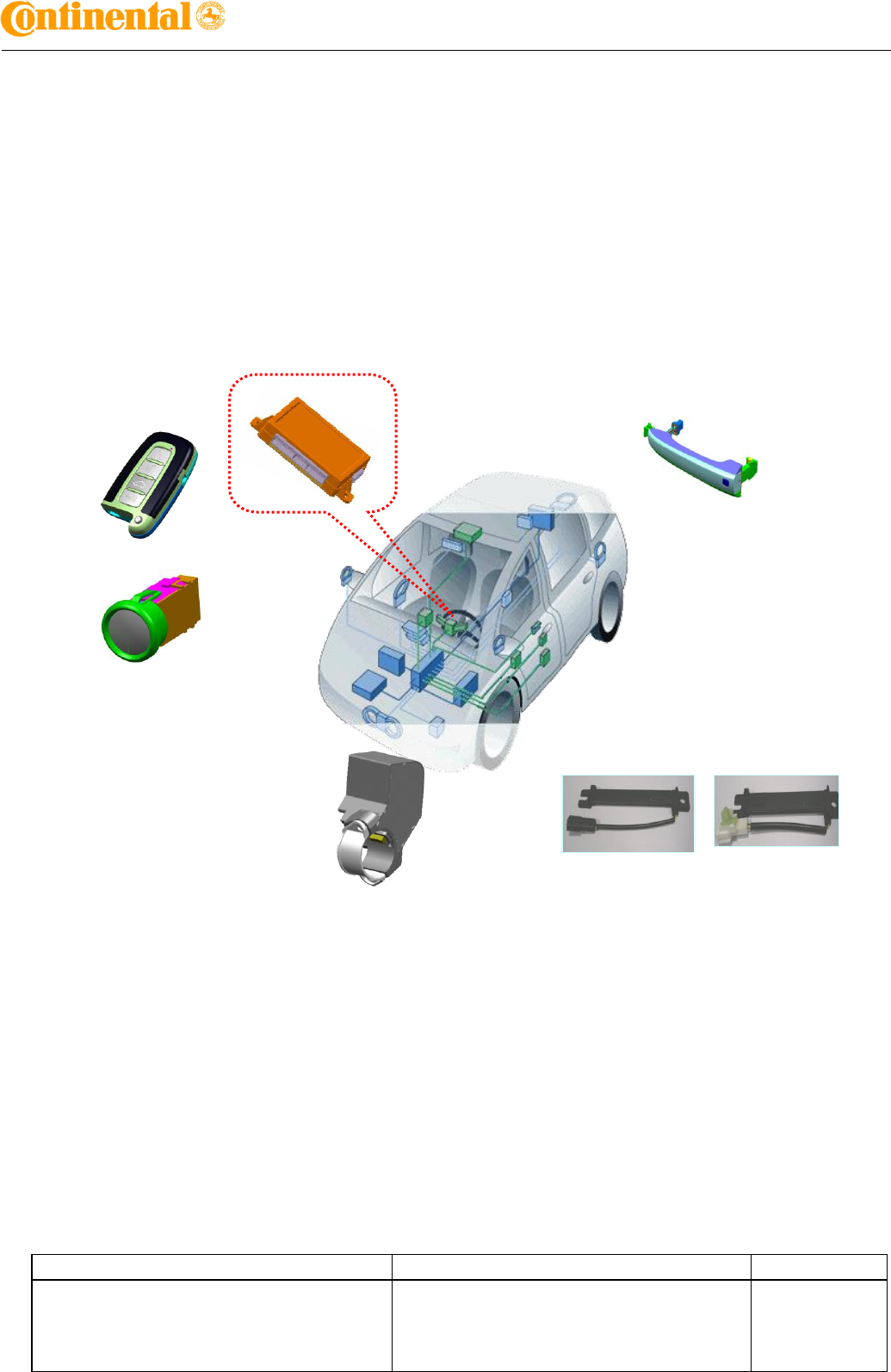
Figure 1: Offered System Components
FOB Key
LF Antenna
HI IBU
Start Stop Button
(Immobilizer Antenna included)
ESCL
Antenna coil housing

Editor :
J. Heo
Document name
Project code
Version:
0.1
May, 18, 2015
ECO / DF No.
Identification No. : Document No.
File:
User Manual for HI IBU_ENG
Page 12 / 13
.
Proprietary data, company confidential. All rights reserved.
Confié à titre de secret d'entreprise. Tous droits réservés.
Comunicado como segredo empresarial. Reservados todos os direitos.
Confidado como secreto industrial. Nos reservamos todos los derechos.
.
.
Weitergabe sowie Vervielfältigung dieser Unterlage, Ver-
wertung und Mitteilung ihres Inhalts nicht gestattet, soweit
nicht ausdrücklich zugestanden. Zuwiderhandlungen ver-
pflichten zu Schadenersatz. Alle Rechte vorbehalten, insbe-
sondere für den Fall der Patenterteilung oder GM-Eintragung.
.
2.3 HI IBU ECU
IBU ECU manages all functions related to “Passive Access”, “Passive Unlocking” ,
“Passive Authorization for Operation”, "Terminal control" .
IBU ECU reads the inputs (Door Lock/unlock, SSB SW, ESCL unlock status, PARK
position Switch, Brake input SW etc.), controls the outputs (e.g. exterior or interior
antennas, terminal control output, ESCL power, Immobilizer antenna), and
communicates via the CAN (depends on the vehicle) as well as a single line interface
to further devices of the car.
For the communication with the SMART KEY FOB, IBU ECU generates a request
(challenge) as an encoded and modulated 125 kHz signal at the inductive antenna
outputs and receives the SMART KEY FOB’s response via the RF receiver.
Or for immobilizer communicaiton, IBU ECU sends 125Khz LF signal to SSB's
immobilizer antenna, and receives Response from Immobilizer antenna.
The main functional blocks of the IBU ECU are:
Power supply
Microcontroller with FLASH Memory
Single Line Interface to ESCL
Single Line Interface to EMS
Input stage
LF antenna amplifier/driver
Immobilizer Antenna output
ESCL power supply
Terminal Control(ACC, IGN1/2, Start Rly)
CAN communication with Other
ECU Internal receiver(433Mhz)
Rear curtain control
Steering wheel heat control
Head lamp wahser relay control
Indicators control
TPMS data receiver
Lamps control
High speed CAN communication
Low speed CAN communicaton
LIN communication

Editor :
J. Heo
Document name
Project code
Version:
0.1
May, 18, 2015
ECO / DF No.
Identification No. : Document No.
File:
User Manual for HI IBU_ENG
Page 13 / 13
.
Proprietary data, company confidential. All rights reserved.
Confié à titre de secret d'entreprise. Tous droits réservés.
Comunicado como segredo empresarial. Reservados todos os direitos.
Confidado como secreto industrial. Nos reservamos todos los derechos.
.
.
Weitergabe sowie Vervielfältigung dieser Unterlage, Ver-
wertung und Mitteilung ihres Inhalts nicht gestattet, soweit
nicht ausdrücklich zugestanden. Zuwiderhandlungen ver-
pflichten zu Schadenersatz. Alle Rechte vorbehalten, insbe-
sondere für den Fall der Patenterteilung oder GM-Eintragung.
.
The LF antenna amplifier/driver generates a 125 kHz sinusoidal carrier signal, which is
distributed to the different antennas.
The signal for Interior antenna and exterior antenna is 100%-ASK modulated by
switching on and off the carrier (the data is Manchester encoded). The power of the
carrier is adjustable by software, which means, it is possible to set the power level of
the antenna driver for every LF-telegram (e.g. power level stored in the EEPROM) in
case of PASE LF Antenna.
And also the signal for immobilizer antenna is ASK modulated signal. Amplitude Shift
Keying for write and AM/PM for the read operation. The receiver charteristics(amplifier
gain, filter cutoff frequencies) can be optimized to system and transponder
requirements.
Editor :
KN.Kim
Document name
Project code
Version:
1.0
Jul. 16. 2012
ECO / DF No.
Identification No. : Document No.
File:
User Manual for Card key_FCC_IC
Page 6 / 6
.
Proprietary data, company confidential. All rights reserved.
Confié à titre de secret d'entreprise. Tous droits réservés.
Comunicado como segredo empresarial. Reservados todos os direitos.
Confidado como secreto industrial. Nos reservamos todos los derechos.
.
.
Weitergabe sowie Vervielfältigung dieser Unterlage, Ver-
wertung und Mitteilung ihres Inhalts nicht gestattet, soweit
nicht ausdrücklich zugestanden. Zuwiderhandlungen ver-
pflichten zu Schadenersatz. Alle Rechte vorbehalten, insbe-
sondere für den Fall der Patenterteilung oder GM-Eintragung.
.
3. Homologation
FCC Compliance Statement.
Do Not
Any changes or modifications to the equipment not expressly
approved by the party responsible for compliance could void
user’s authority to operate the equipment.
IC Compliance Statement.
Le present appareil est conforme aux CNR d’Industrie Canada applicables aux appareils radio
exempts de licence. L’exploitation est autorisee aux deux conditions suivantes :
(1) l’appareil ne doit pas produire de brouillage, et
(2) l’utilisateur de l’appareil doit accepter tout brouillage radioelectrique subi, meme si le
brouillage est susceptible d’en compromettre le fonctionnement.
This device complies with part 15 of the FCC Rules.
Operation is subject to the following two conditions :
(1) This device may not cause harmful interference, and
(2) This device must accept any interference received, including
interference that may cause undesired operation.
This device complies with Industry Canada licence-exempt RSS standard(s).
Operation is subject to the following two conditions:
(1) this device may not cause interference, and
(2) this device must accept any interference, including interference that may
cause undesired operation of the device.