Continental Automotive Systems SVISMKFNA04 Smart Key Fob User Manual for SMK ECU Fob
Continental Automotive Systems Corporation Smart Key Fob for SMK ECU Fob
User Manual

.
Proprietary data, company confidential. All rights reserved.
Confié à titre de secret d'entreprise. Tous droits réservés.
Comunicado como segredo empresarial. Reservados todos os direitos.
Confidado como secreto industrial. Nos reservamos todos los derechos.
.
Weitergabe sowie Vervielfältigung dieser Unterlage, Ver
-
wertung und Mitteilung ihres Inhalts nicht gestattet, soweit
nicht ausdrücklich zugestanden. Zuwiderhandlungen ver
-
pflichten zu Schadenersatz. Alle Rechte vorbehalten, insbe-
sondere für den Fall der Patenterteilung oder GM-Eintragung
SV SASCO Identification No. :
Document : Function Description /
User Manual
for
Smart Key System
Project : Smart Key ECU & Smart Key Fob
Project Code :
Version: 0.2
Date: Sep. 18 '06
Engineering change order-No.:
Design Freeze No.:
Number of pages: 14
Filename: User Manual for SMK ECU & Fob
Editor : KK Ko Document name Project code
ECO / DF No.
Version: 0.5 Aug. 10. 2006
File: User Manual for SMK ECU & Fob
Identification No. : Document No.
Page 2 / 14
.
Proprietary data, company confidential. All rights reserved.
Confié à titre de secret d'entreprise. Tous droits réservés.
Comunicado como segredo empresarial. Reservados todos os direitos.
Confidado como secreto industrial. Nos reservamos todos los derechos.
.
Weitergabe sowie Vervielfältigung dieser Unterlage, Ver
-
wertung und Mitteilung ihres Inhalts nicht gestattet, soweit
nicht ausdrücklich zugestanden. Zuwiderhandlungen ver
-
pflichten zu Schadenersatz. Alle Rechte vorbehalten, insbe-
sondere für den Fall der Patenterteilung oder GM-Eintragung
Operation Guide
This device complies with part 15 of the FCC Rules. Operation
is subject to the following two conditions:
(1) This device may not cause harmful interference, and
(2) This device must accept any interference received,
including interference that may cause undesired operation.
Caution !
Any changes or modifications to the equipment not expressly approved by the party responsible for
compliance could void user’s authority to operate the equipment.

Editor : KK Ko Document name Project code
ECO / DF No.
Version: 0.5 Aug. 10. 2006
File: User Manual for SMK ECU & Fob
Identification No. : Document No.
Page 3 / 14
.
Proprietary data, company confidential. All rights reserved.
Confié à titre de secret d'entreprise. Tous droits réservés.
Comunicado como segredo empresarial. Reservados todos os direitos.
Confidado como secreto industrial. Nos reservamos todos los derechos.
.
Weitergabe sowie Vervielfältigung dieser Unterlage, Ver
-
wertung und Mitteilung ihres Inhalts nicht gestattet, soweit
nicht ausdrücklich zugestanden. Zuwiderhandlungen ver
-
pflichten zu Schadenersatz. Alle Rechte vorbehalten, insbe-
sondere für den Fall der Patenterteilung oder GM-Eintragung
Contents list Page
1 System configulation 4
1.1 scope of SMART KEY SYSTEM 4
1.2 short description of the SYSTEM 4
1.2.1 General Definition of SMART KEY 4
1.2.2 Wireless Communication 4
1.2.3 concept Description 4
1.2.4 System Architecture 5
1.2.5 Main Functions 6
1.3 System Overview / Block Diagram 7
2 SMK ECU Configuration 9
2.1 Block Diagram 9
2.2 Pin Description 10
2.3 SMART Key Ecu (SMK ECU) 11
3 SMK Fob Configuration (Transmitter) 13
3.1 Block Diagram 13
3.2 Technical Data of SMK Fob 13
4 SMK ECU Test Board for homologation 13
4.1 Shape of tool box 13
4.2 Switch 14
4.3 Method to use Test board 14
5 SMK Fob for homologation 14
5.1 Button operation for homologation 14

Editor : KK Ko Document name Project code
ECO / DF No.
Version: 0.5 Aug. 10. 2006
File: User Manual for SMK ECU & Fob
Identification No. : Document No.
Page 4 / 14
.
Proprietary data, company confidential. All rights reserved.
Confié à titre de secret d'entreprise. Tous droits réservés.
Comunicado como segredo empresarial. Reservados todos os direitos.
Confidado como secreto industrial. Nos reservamos todos los derechos.
.
Weitergabe sowie Vervielfältigung dieser Unterlage, Ver
-
wertung und Mitteilung ihres Inhalts nicht gestattet, soweit
nicht ausdrücklich zugestanden. Zuwiderhandlungen ver
-
pflichten zu Schadenersatz. Alle Rechte vorbehalten, insbe-
sondere für den Fall der Patenterteilung oder GM-Eintragung
1 System configulation
1.1 scope of SMART KEY SYSTEM
The System offers the following features:
• passive access for two doors, driver side and passenger side as well as trunk/tailgate
• passive start after interior detection of the SMART KEY FOB (without interior trunk and
hat shelf detection)
• LF-RF communication (based on Siemens’ SMART KEY system)
• passive access/locking of the two front doors via a toggle push button in the door
handles
• passive access trunk/tailgate via the trunk lid switch at the trunk
• max. 2 SMART KEY FOBs can be handled by the system
• immobilizer backup antenna driver integrated into MSL
• communication to the engine management system via a single line interface
• communication to the MSL via a single line interface
• block of the steering column by the MSL device
1.2 short description of the SYSTEM
1.2.1 General Definition of SMART KEY
The SMART KEY system is a system that allows the user to access and operate a
vehicle in a very convenient way. To access the vehicle no traditional key or remote
control unit is needed.
The user carries a SMART KEY FOB which itself does not require any conscious
actions by the user (e.g. operate a button). The SMART KEY system is triggered by
pressing a push button in the door handle.
After being triggered the vehicle sends out a request in a limited range. If the
SMART KEY FOB receives this request, it automatically sends a response to the
vehicle. Then the system decides whether to perform a particular action (unlocking,
locking…) or remain inactive.
In a similar manner the vehicle’s Mechatronic Steering Lock (MSL) is released.
Again, a communication between the vehicle and the SMART KEY FOB is needed
before any actions will be performed.
1.2.2 Wireless Communication
Electromagnetic waves are used to exchange information between the vehicle and the
SMART KEY FOB. Both, vehicle and SMART KEY FOB are equipped with a transmitter,
a receiver and several antennas.
1.2.3 concept Description
With this concept it is possible to have a set of interior antennas that covers the vehicle’s
interior and a set of exterior antennas that covers the vehicle’s exterior.

Editor : KK Ko Document name Project code
ECO / DF No.
Version: 0.5 Aug. 10. 2006
File: User Manual for SMK ECU & Fob
Identification No. : Document No.
Page 5 / 14
.
Proprietary data, company confidential. All rights reserved.
Confié à titre de secret d'entreprise. Tous droits réservés.
Comunicado como segredo empresarial. Reservados todos os direitos.
Confidado como secreto industrial. Nos reservamos todos los derechos.
.
Weitergabe sowie Vervielfältigung dieser Unterlage, Ver
-
wertung und Mitteilung ihres Inhalts nicht gestattet, soweit
nicht ausdrücklich zugestanden. Zuwiderhandlungen ver
-
pflichten zu Schadenersatz. Alle Rechte vorbehalten, insbe-
sondere für den Fall der Patenterteilung oder GM-Eintragung
For an unambiguous separation between the vehicle’s interior and exterior it is sufficient
that at least one area is covered exactly by the corresponding operating ranges of the
antennas.
The functions of the SMART KEY system have to be provided in a clearly defined and
limited range. For the up-link from the vehicle to the SMART KEY FOB, a magnetic field
with a frequency of 125 kHz and ASK modulation is used. Inductive antennas in and at
the vehicle radiate the electromagnetic energy.
Technical aspects of 125 kHz – magnetic field:
• virtually no reflections,
• cubical decrease of field strength → allows good range control,
• released frequency band (ISM),
• high penetration,
• low quiescent current demand due to 125 kHz input stage (SMART KEY FOB),
• less sensitive for detuning compared to higher frequency.
For the down-link from the SMART KEY FOB to the vehicle, the standard radio frequency
(RF) is used (similar to the classic remote control functions) with FSK modulation.
1.2.4 System Architecture
The system is designed as an optional system, making it possible to equip vehicles of the
same car-Line with different levels of access control systems.
The system is suitable to be integrated into an existing architecture that provides central
locking functions with standard remote control. This proposal assumes that the following
functions / devices are already present in the vehicle’s architecture.
• Central locking system (latch / motor – drivers etc.)
• Standard body control functions
• Warning buzzer
Editor : KK Ko Document name Project code
ECO / DF No.
Version: 0.5 Aug. 10. 2006
File: User Manual for SMK ECU & Fob
Identification No. : Document No.
Page 6 / 14
.
Proprietary data, company confidential. All rights reserved.
Confié à titre de secret d'entreprise. Tous droits réservés.
Comunicado como segredo empresarial. Reservados todos os direitos.
Confidado como secreto industrial. Nos reservamos todos los derechos.
.
Weitergabe sowie Vervielfältigung dieser Unterlage, Ver
-
wertung und Mitteilung ihres Inhalts nicht gestattet, soweit
nicht ausdrücklich zugestanden. Zuwiderhandlungen ver
-
pflichten zu Schadenersatz. Alle Rechte vorbehalten, insbe-
sondere für den Fall der Patenterteilung oder GM-Eintragung
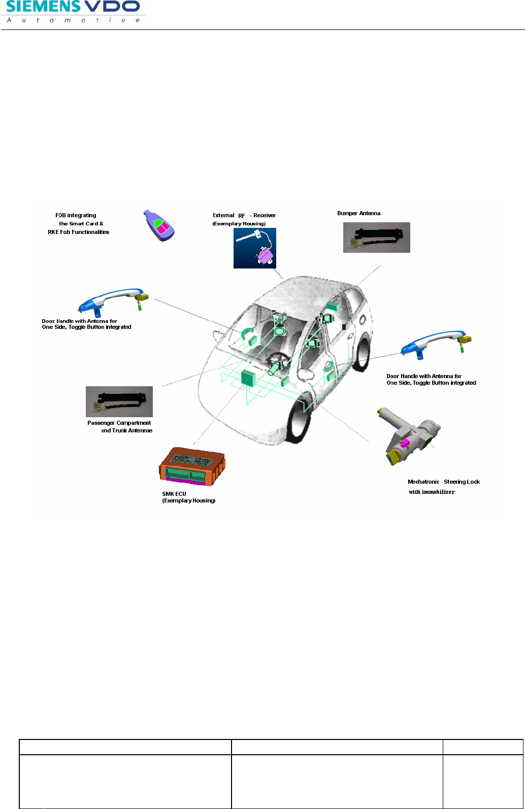
1.2.5 Main Functions
• The system allows the user to access and exit (unlock and lock) the vehicle without
performing any actions with the SMART KEY FOB.
• The system allows the user to release the MSL and to switch the power modes (Off,
Accessory, Ignition), as well as to start and stop the vehicle’s engine without
performing any actions with the SMART KEY FOB.
• Additionally, the system offers a so called “limp home mode”, wherein the user can
operate all vehicle functions by inserting the key into the MSL or by inserting the
mechanical key blade into the door lock.
Figure 1: Offered System Components
Editor : KK Ko Document name Project code
ECO / DF No.
Version: 0.5 Aug. 10. 2006
File: User Manual for SMK ECU & Fob
Identification No. : Document No.
Page 7 / 14
.
Proprietary data, company confidential. All rights reserved.
Confié à titre de secret d'entreprise. Tous droits réservés.
Comunicado como segredo empresarial. Reservados todos os direitos.
Confidado como secreto industrial. Nos reservamos todos los derechos.
.
Weitergabe sowie Vervielfältigung dieser Unterlage, Ver
-
wertung und Mitteilung ihres Inhalts nicht gestattet, soweit
nicht ausdrücklich zugestanden. Zuwiderhandlungen ver
-
pflichten zu Schadenersatz. Alle Rechte vorbehalten, insbe-
sondere für den Fall der Patenterteilung oder GM-Eintragung
1.3 System Overview / Block Diagram
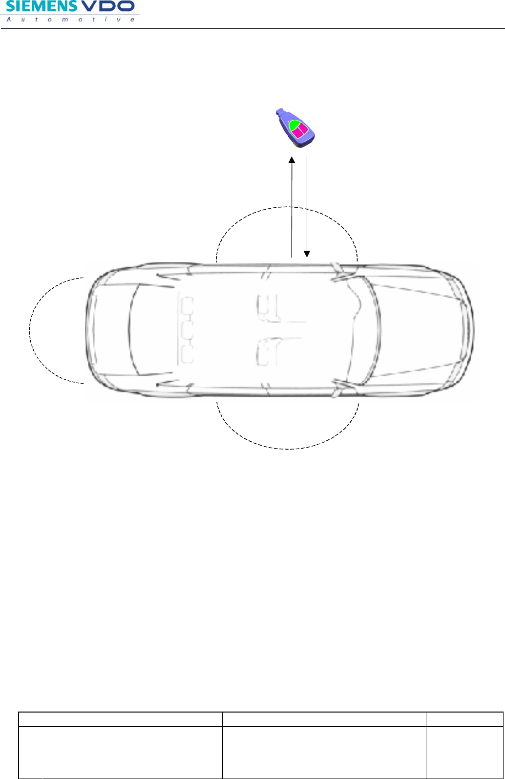
Figure 2: Principle of Communication
Challenge
(LF-Up-link)
Response
(RF-Down-link)
SMART KEY FOB
Passive Access
Detection Range
Passive Access
Detection Range
Editor : KK Ko Document name Project code
ECO / DF No.
Version: 0.5 Aug. 10. 2006
File: User Manual for SMK ECU & Fob
Identification No. : Document No.
Page 8 / 14
.
Proprietary data, company confidential. All rights reserved.
Confié à titre de secret d'entreprise. Tous droits réservés.
Comunicado como segredo empresarial. Reservados todos os direitos.
Confidado como secreto industrial. Nos reservamos todos los derechos.
.
Weitergabe sowie Vervielfältigung dieser Unterlage, Ver
-
wertung und Mitteilung ihres Inhalts nicht gestattet, soweit
nicht ausdrücklich zugestanden. Zuwiderhandlungen ver
-
pflichten zu Schadenersatz. Alle Rechte vorbehalten, insbe-
sondere für den Fall der Patenterteilung oder GM-Eintragung
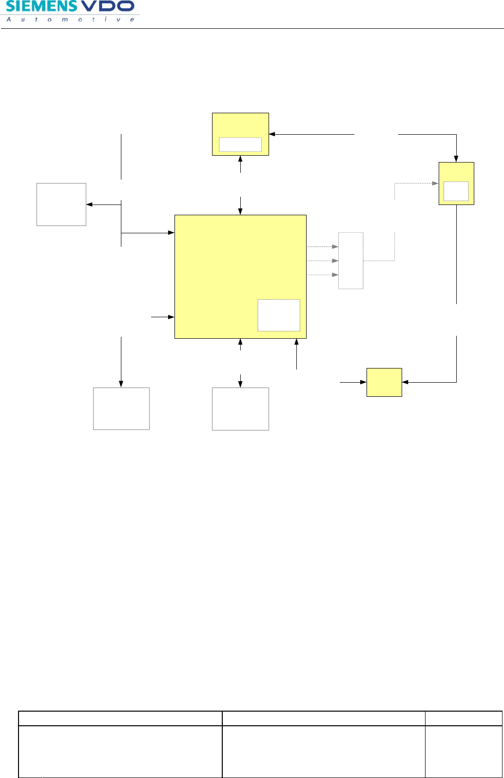
SmartKey
ECU
Body CAN/
LIN
BCM,
DDM,
...
Single line
serial communication
10.4 kBd / KWP2000
Diag-Tool
Single line
serial communication
4.8 kBd
EMS
SMK
LF driver
Single line
serial communication
9.6 kBd
Transponder
communication
Fob
SMK
LF
MSL
Immobilizer
SRx
Single line
serial communication
9.6 kBd
RF communication
(RKE and Pase)
1kBd FSK
315/433/447 MHz
LF antenna
(SMK)
LF communication
(SMK)
3.9 kBd ASK
125 KHz
System Architecture for SmartKey
Figure 3: System Block Diagram
Editor : KK Ko Document name Project code
ECO / DF No.
Version: 0.5 Aug. 10. 2006
File: User Manual for SMK ECU & Fob
Identification No. : Document No.
Page 9 / 14
.
Proprietary data, company confidential. All rights reserved.
Confié à titre de secret d'entreprise. Tous droits réservés.
Comunicado como segredo empresarial. Reservados todos os direitos.
Confidado como secreto industrial. Nos reservamos todos los derechos.
.
Weitergabe sowie Vervielfältigung dieser Unterlage, Ver
-
wertung und Mitteilung ihres Inhalts nicht gestattet, soweit
nicht ausdrücklich zugestanden. Zuwiderhandlungen ver
-
pflichten zu Schadenersatz. Alle Rechte vorbehalten, insbe-
sondere für den Fall der Patenterteilung oder GM-Eintragung
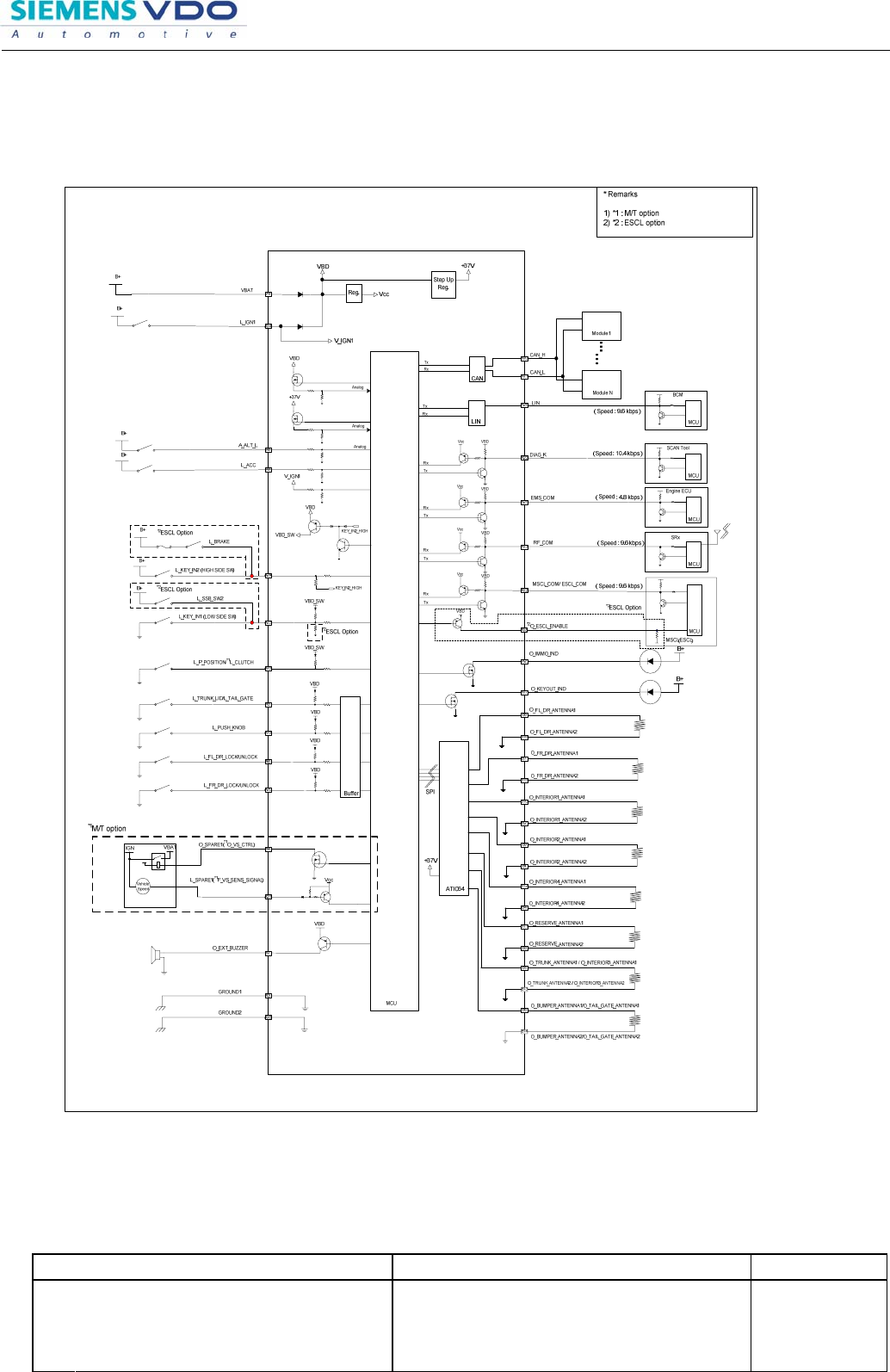
2 SMK ECU Configuration
2.1 Block Diagram
Editor : KK Ko Document name Project code
ECO / DF No.
Version: 0.5 Aug. 10. 2006
File: User Manual for SMK ECU & Fob
Identification No. : Document No.
Page 10 / 14
.
Proprietary data, company confidential. All rights reserved.
Confié à titre de secret d'entreprise. Tous droits réservés.
Comunicado como segredo empresarial. Reservados todos os direitos.
Confidado como secreto industrial. Nos reservamos todos los derechos.
.
Weitergabe sowie Vervielfältigung dieser Unterlage, Ver
-
wertung und Mitteilung ihres Inhalts nicht gestattet, soweit
nicht ausdrücklich zugestanden. Zuwiderhandlungen ver
-
pflichten zu Schadenersatz. Alle Rechte vorbehalten, insbe-
sondere für den Fall der Patenterteilung oder GM-Eintragung
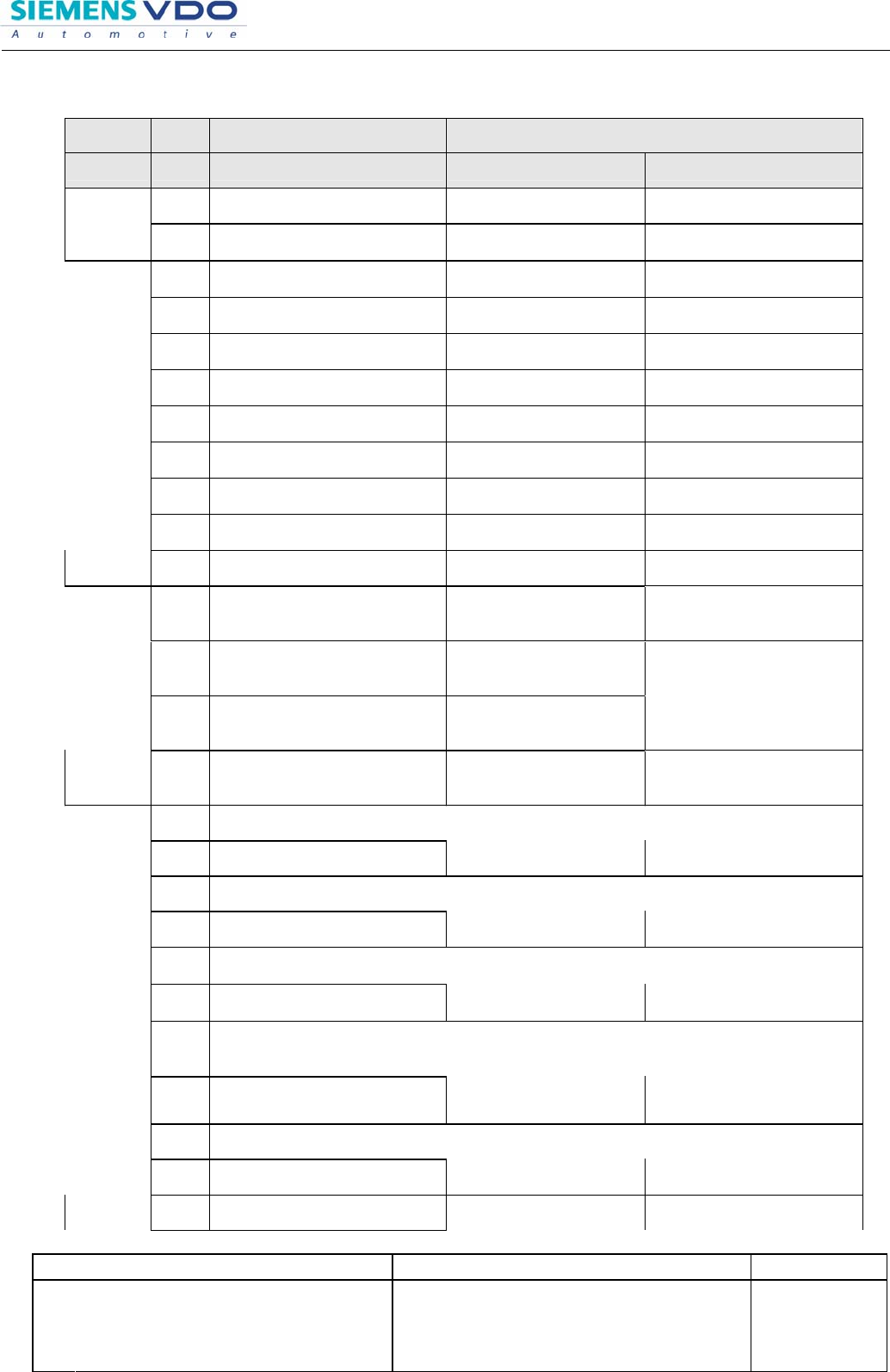
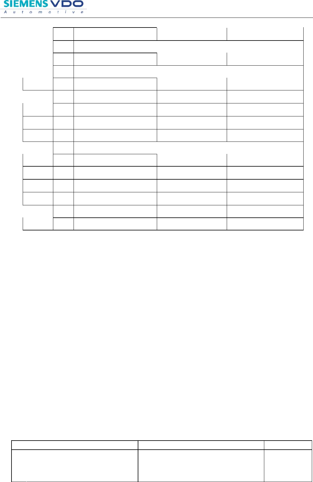
2.2 Pin Description
Function I/O Pin Description Load Configuration
OFF configuration ON Configuration
A1 VBAT Switch Open
Connect to main Battery via
Switch
Analog
Input A8 A_ALT_L Switch Open Connect to main Battery via
Switch
A9 L_ACC Switch Open Connect to main Battery via
Switch
A14 L_IGN1 Switch Open Connect to main Battery via
Switch
A19 L_PUSH_KNOB Switch Open Connect to main Ground via
Switch
A6 L_FL_DR_LOCK/ UNLOCK Switch Open Connect to main Ground via
Switch
A20 L_FR _DR_LOCK/ UNLOCK Switch Open Connect to main Ground via
Switch
A5 L_TRUNK_LID/L_TAIL_GATE Switch Open Connect to main Ground via
Switch
A15 L_P_POSITION/ L_CLUTCH Switch Open Connect to main Ground via
Switch
A23 L_KEY_IN1(LOW SIDE SW) Switch Open Connect to main Ground via
Switch
Logic Input
A24 L_KEY_IN2 (HIGH SIDE SW) Switch Open Connect to main Battery via
Switch
A18 O_ESCL_ENABLE
(O_SPARE2) Output Off Connect to main Ground via
1KOhm resistor and Output
ON
A17 O_KEYOUT_IND Output Off Connect to main Battery via
resistor 1KOhm and Output
ON
A7 O_EXT_BUZZER Output Off Connect to main Ground via
1KOhm resistor and Output
ON
Output
A2 O_IMMO_IND Output Off Connect to main Battery via
resistor 1KOhm and Output
ON
B8 O_FL_DR_ANTENNA1
B16 O_FL_DR_ANTENNA2
Output Off Connect to main Ground via
200uH Antenna and Output
ON
B7 O_FR_DR_ANTENNA1
B15 O_FR_DR_ANTENNA2
Output Off Connect to main Ground via
200uH Antenna and Output
ON
B6 O_BUMPER /
O_TAIL_GATE_ANTENNA1
B14 O_BUMPER /
O_TAIL_GATE_ANTENNA2
Output Off Connect to main Ground via
200uH Antenna and Output
ON
B5 O_TRUNK_ANTENNA1 /
O_INTERIOR3_ANTENNA1
B13 O_TRUNK_ANTENNA2 /
O_INTERIOR3_ANTENNA2
Output Off Connect to main Ground via
200uH Antenna and Output
ON
B10 O_INTERIOR1_ANTENNA1
B2 O_INTERIOR1_ANTENNA2
Output Off Connect to main Ground via
200uH Antenna and Output
ON
Antenna
B9 O_INTERIOR2_ANTENNA1
Output Off Connect to main Ground via
Editor : KK Ko Document name Project code
ECO / DF No.
Version: 0.5 Aug. 10. 2006
File: User Manual for SMK ECU & Fob
Identification No. : Document No.
Page 11 / 14
.
Proprietary data, company confidential. All rights reserved.
Confié à titre de secret d'entreprise. Tous droits réservés.
Comunicado como segredo empresarial. Reservados todos os direitos.
Confidado como secreto industrial. Nos reservamos todos los derechos.
.
Weitergabe sowie Vervielfältigung dieser Unterlage, Ver
-
wertung und Mitteilung ihres Inhalts nicht gestattet, soweit
nicht ausdrücklich zugestanden. Zuwiderhandlungen ver
-
pflichten zu Schadenersatz. Alle Rechte vorbehalten, insbe-
sondere für den Fall der Patenterteilung oder GM-Eintragung
B1 O_INTERIOR2_ANTENNA2 200uH Antenna and Output
ON
B12 O_INTERIOR4_ANTENNA1
B4 O_INTERIOR4_ANTENNA2
Output Off Connect to main Ground via
200uH Antenna and Output
ON
B11 O_RESERVE_ANTENNA1
B3 O_RESERVE_ANTENNA2
Output Off Connect to main Ground via
200uH Antenna and Output
ON
A4 O_SPARE1
(O_VS_CTRL) Output Off Reserve ( Relay )
VS
A21 L_SPARE1
(F_VS_SIGNAL) Input Open Reserve ( Generate 200Hz)
Diagnostic A22 DIAG_K Open Gernernal communication with
LTT
EMS Com. A25 EMS_COM Open Comunication with LTT
A10 CAN_H(L_SPARE3)
CAN A11 CAN_L(L_SPARE4) Open Comunication with LTT in
case of CAN option
Lin A26 LIN(L_SPARE2) Open Communication with LTT in
case of LIN option
RF
interface A13 RF_COM Open Comunication with LTT
MSL / ESL
Com. A12 MSCL_COM/ ESCL_COM Open Comunication with LTT
A3 GROUND1 Main ground Main ground
Ground A16 GROUND2 Main ground Main ground
2.3 SMART Key Ecu (SMK ECU)
The SMK ECU manages all functions related to “Passive Access”, “Passive Unlocking”
and “Passive Authorization for Operation”.
It reads the inputs (Push button, MSL Knob Push Switch, PARK position Switch),
controls the outputs (e.g. exterior and interior antennas), and communicates via the
CAN/LIN (depends on the vehicle) as well as a single line interface to further devices of
the car.
For communication with the SMART KEY FOB, the SMK ECU generates a request
(challenge) as an encoded and modulated 125 kHz signal at the inductive antenna
outputs and receives the SMART KEY FOB’s response via the external RF receiver.
The main functional blocks of the SMK ECU are:
• Power supply
• Microcontroller with FLASH Memory
• Single Line Interface to MSL
• Single Line Interface to SRX
• Single Line Interface to EMS
• Input stage
• LF antenna amplifier/driver
• LIN communication with BCM/ETACS (except EN, VQ ; CAN communication)

Editor : KK Ko Document name Project code
ECO / DF No.
Version: 0.5 Aug. 10. 2006
File: User Manual for SMK ECU & Fob
Identification No. : Document No.
Page 12 / 14
.
Proprietary data, company confidential. All rights reserved.
Confié à titre de secret d'entreprise. Tous droits réservés.
Comunicado como segredo empresarial. Reservados todos os direitos.
Confidado como secreto industrial. Nos reservamos todos los derechos.
.
Weitergabe sowie Vervielfältigung dieser Unterlage, Ver
-
wertung und Mitteilung ihres Inhalts nicht gestattet, soweit
nicht ausdrücklich zugestanden. Zuwiderhandlungen ver
-
pflichten zu Schadenersatz. Alle Rechte vorbehalten, insbe-
sondere für den Fall der Patenterteilung oder GM-Eintragung
The LF antenna amplifier/driver generates a 125 kHz sinusoidal carrier signal which is
distributed to the different antennas.
The signal is 100%-ASK modulated by switching on and off the carrier (the data is
Manchester encoded). The power of the carrier is adjustable by software, which means,
it is possible to set the power level of the antenna driver for every LF-telegram (e.g.
power level stored in the EEPROM).
The LF antenna driver consists of a number of outputs with different switching features.
1. switch on/off driver door handle antenna
2. switch on/off passenger door handle antenna
3. switch on/off bumper antenna for access to the trunk
4. switch on/off interior antennae
5. switch on/off trunk antenna (except SUV)
The SMK ECU comprises:
• the electronics described above
• a plastic housing
Emitting LF Antennas:
Inductive antennas in and at the vehicle are used to transform the current, driven by the SMK ECU
antenna driver, into a 125 kHz magnetic field, which is the carrier for the SMART KEY challenge.
Three antennas cover the vehicle’s exterior: two antennas in the Door Handles (DS and PS) cover
the area around the doors; one antenna in the rear bumper covers the area around the trunk/tailgate.
Up to three antennas cover the vehicle’s interior and the trunk interior: two in the passenger
compartment and one in the trunk. (In case of SUV, Three antennas cover the vehicle’s interior and
no trunk antenna)
Those antennas are based on either Vitrovac™ or ferrite core and have twisted pair terminals on
standard pin header.
Editor : KK Ko Document name Project code
ECO / DF No.
Version: 0.5 Aug. 10. 2006
File: User Manual for SMK ECU & Fob
Identification No. : Document No.
Page 13 / 14
.
Proprietary data, company confidential. All rights reserved.
Confié à titre de secret d'entreprise. Tous droits réservés.
Comunicado como segredo empresarial. Reservados todos os direitos.
Confidado como secreto industrial. Nos reservamos todos los derechos.
.
Weitergabe sowie Vervielfältigung dieser Unterlage, Ver
-
wertung und Mitteilung ihres Inhalts nicht gestattet, soweit
nicht ausdrücklich zugestanden. Zuwiderhandlungen ver
-
pflichten zu Schadenersatz. Alle Rechte vorbehalten, insbe-
sondere für den Fall der Patenterteilung oder GM-Eintragung
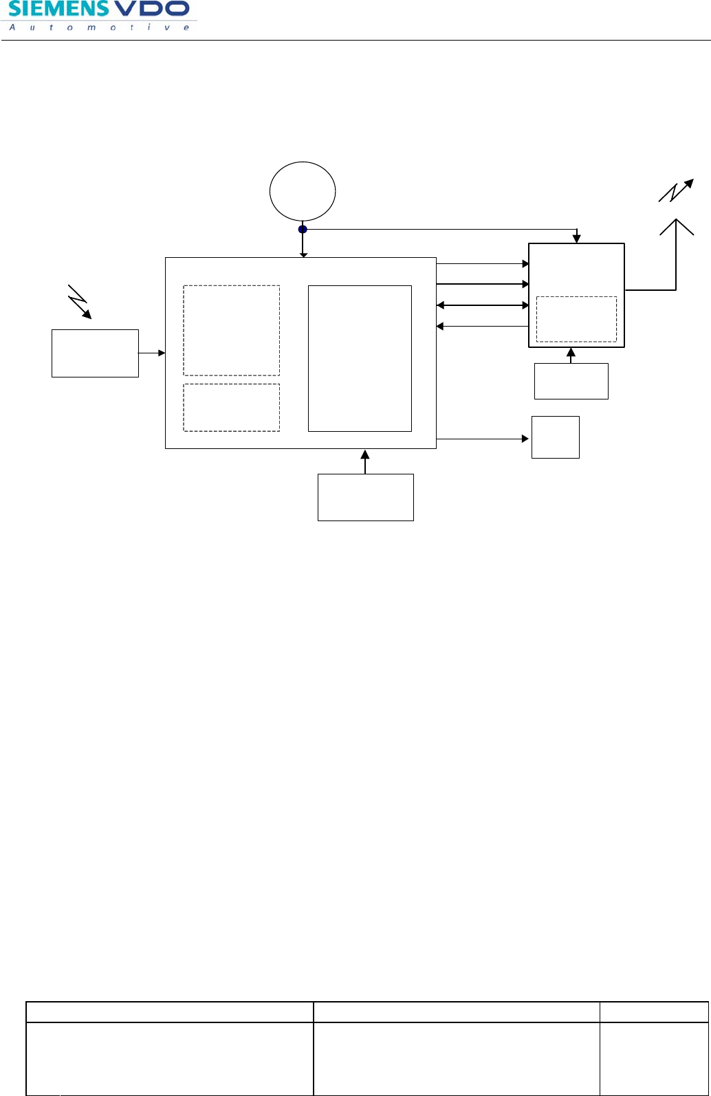
3 SMK Fob Configuration (Transmitter)
3.1 Block Diagram
Processor
PLL
Transmitter
Inductive
Receiver
125 KHz
Batterie
Buttons
coils
X,Y,Z axis
Transponder
Unit
Crystal
LED
Configuration
registers
Mircrocontroller
RF Antenna
LF (125kHz, ASK)
RF (FSK)
XCLOCK
CLOCK
ENABLE
DATA
3.2 Technical Data of SMK Fob
Carrier Frequency NA/China : 315MHz
Field Strength NA/China : < 75.6uV/m at 3m
Deviation NA/China : 65~80kHz
Carrier Frequency EU : 433.92MHz
Field Strength EU : < 90uV/m at 3m
Deviation NA/China : 65~80kHz
Carrier Frequency Korea : 447.725MHz
Output power Korea : < 10mW
Deviation Korea : < 5kHz
Modulation : FSK
Baud rate of RF : 1kBd
Supply voltage : 3V
Battery Type : Lithium, CR2032
4 SMK ECU Test Board for homologation
4.1 Shape of tool box
Editor : KK Ko Document name Project code
ECO / DF No.
Version: 0.5 Aug. 10. 2006
File: User Manual for SMK ECU & Fob
Identification No. : Document No.
Page 14 / 14
.
Proprietary data, company confidential. All rights reserved.
Confié à titre de secret d'entreprise. Tous droits réservés.
Comunicado como segredo empresarial. Reservados todos os direitos.
Confidado como secreto industrial. Nos reservamos todos los derechos.
.
Weitergabe sowie Vervielfältigung dieser Unterlage, Ver
-
wertung und Mitteilung ihres Inhalts nicht gestattet, soweit
nicht ausdrücklich zugestanden. Zuwiderhandlungen ver
-
pflichten zu Schadenersatz. Alle Rechte vorbehalten, insbe-
sondere für den Fall der Patenterteilung oder GM-Eintragung
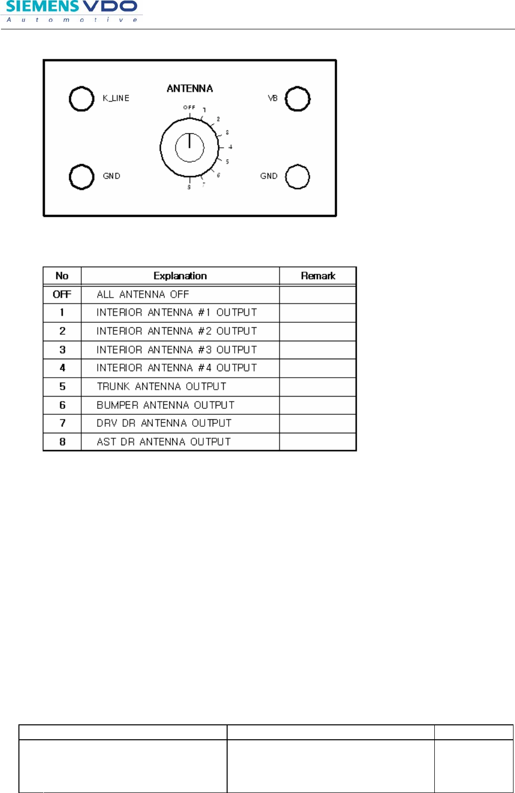
4.2 Switch
4.3 Method to use Test board
- Prepare VB, GND, K_LINE, GND wire to connect Tool Box.
- Connect Power(VB, GND) to Tool Box.
- Connect communication line(K-LINE, GND) to Tool Box.
- Connect Harness connector to SMK ECU Unit.
- After selecting swich No. , give VB power to test board.(Do not give overvoltage)
5 SMK Fob for homologation
5.1 Button operation for homologation
1st time button pressing : Low side Frequency (Carrier wave continueous mode)
2nd time button pressing : High side Frequency (Carrier wave continueous mode)
3rd time button pressing : FSK Modulation (Modulated wave continueous mode)
4th time button pressing : Stop operation.