Continental Automotive Technologies 5WK47594 Tire Pressure Monitoring System User Manual Annex No 5
Continental Automotive GmbH Tire Pressure Monitoring System Annex No 5
User Manual
Annex No.5
Technical Description
Tire Pressure Monitoring System (TPMS) 5WK4 7594

SIEMENS VDO Automotive SV C BC P2 RF TG
IC: 267T-5WK47594 FCC ID:KR55WK47594
\\POSTZULA\Tpms_TG\TG1B_DC_LR\Landrover_Jaguar\Technical Doku_ECU_LF-Antenna
\Usermanual_ECU_LFantenna.pdf 1 of 5
User Manual / Functional Description
of the
Siemens VDO
Tire Pressure Monitoring System - ECU
Type
5WK4 7593 (Europe)
5WK4 7594 (USA)

SIEMENS VDO Automotive SV C BC P2 RF TG
IC: 267T-5WK47594 FCC ID:KR55WK47594
\\POSTZULA\Tpms_TG\TG1B_DC_LR\Landrover_Jaguar\Technical Doku_ECU_LF-Antenna
\Usermanual_ECU_LFantenna.pdf 2 of 5
General description
The tire pressure monitoring system (TPMS) consists of an control unit (ECU)
with 4 LF antennas. The TPMS transmitter is mounted on the valve stem of the
tire. The RF receiver is integrated on the ECU.
The ECU contains the driver circuitry for the LF antennas (4 per system) and the
integrated RF receiver (which has been already homologated).
The LF antennas are only necessary to locate the tire position after a tire change.
The antennas are fixed on the steering stub. When the antennas send a 125 kHz
signal to the TPMS transmitter the transponder will be activated and the location
of the tire and the corresponding TPMS transmitter can be read.
The localisation function enables the vehicle driver to get information about which
tire a pressure loss has been detected.
SIEMENS VDO Automotive SV C BC P2 RF TG
IC: 267T-5WK47594 FCC ID:KR55WK47594
\\POSTZULA\Tpms_TG\TG1B_DC_LR\Landrover_Jaguar\Technical Doku_ECU_LF-Antenna
\Usermanual_ECU_LFantenna.pdf 3 of 5
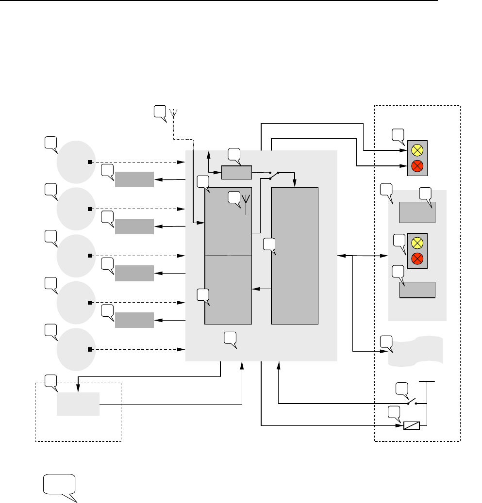
Block diagram
The block diagram below shows the main electronic units of the TPMS ECU:
Vehicle
Instrument Pack
Land Rover’s Scope
& Responsibility
TPM
ECU
Tyre
Sensor
Module
FR
Tyre
Sensor
Module
RL
Tyre
Sensor
Module
RR
Tyre
Sensor
Module
Spare
Vehicle Systems’
Interface
Tyre
Sensor
Module
FL
TPM Input
Push Button
315 or 433 MHz
RF Tx Channel
Text &/Or
Icon Display
Sounder
LEDs
Passive LF
Initiator FL
Passive LF
Initiator FR
Passive LF
Initiator RL
Passive
LF
Initiator RR
RF
Receiver
LF
Drivers
Controller
Push Button
Contact
Push Button
LED Drive
LEDs
Land Rover’s Scope
& Responsibility
LED Drive*
Volcano
CAN
2 Wire
Drive
2 Wire
Drive
2 Wire
Drive
2 Wire
Drive
Provision for Ext
RF Antenna
Provision for
Spare Sensor
LED Drive*
1
1
1
1
1
2
3
3
4
5
6
7
8
9
10
11
12
12
12
12
13
15
LIN I/F*
Provision
for
Ext RF Rx
* = Components may be removed after FPDS CP build phase
16
Ignition Switch Contact
VBat
17
14
Horn Relay Drive*
12
= 125kHz

SIEMENS VDO Automotive SV C BC P2 RF TG
IC: 267T-5WK47594 FCC ID:KR55WK47594
\\POSTZULA\Tpms_TG\TG1B_DC_LR\Landrover_Jaguar\Technical Doku_ECU_LF-Antenna
\Usermanual_ECU_LFantenna.pdf 4 of 5
Variants
Siemens type designation
Explanation
5WK4 7594 ECU with integrated receiver 315 MHz
5WK4 7593 ECU with integrated receiver 433.92 MHz
5WK4 7595 LF antenna
The two ECU variants use the same schematic, layout and assembly! The
only difference is the integrated RF receiver (which is not subject to this
homologation).
Typical usage pattern (for Europe only)
Worst case calculation:
4 drive cycles in 24 hours
30 minutes to localise the vehicle
• total transmission duration of 120 minutes in 24 hours
Transmitter ON 5 minutes / hour
Transmitter OFF 55 minutes / hour
Duty Cycle: TON / T (ON+OFF) x 100% = 5 / 60 x 100 % = 8.3%
Technical description
Carrier frequency: 125 KHz
Frequency shift: +/- 2%
Modulation: none
Number of channels: 1
Rated Output Power: <40 dBµA/m @ 3 m
Antenna: dedicated
Voltage supply: Vehicle battery
Voltage supply range: 9 to 16 Volts

SIEMENS VDO Automotive SV C BC P2 RF TG
IC: 267T-5WK47594 FCC ID:KR55WK47594
\\POSTZULA\Tpms_TG\TG1B_DC_LR\Landrover_Jaguar\Technical Doku_ECU_LF-Antenna
\Usermanual_ECU_LFantenna.pdf 5 of 5
Label design USA / Canada
Label information
Siemens VDO
5WK47594
IC: 267T-5WK47594
FCC ID:KR55WK47594
User manual information
IC: 267T-5WK47594
FCC ID:KR55WK47594
This device complies with part 15 of
the FCC Rules and RSS-210.
Operation is subject to the following
two conditions: (1) This device may
not cause harmful interference, and
(2) this device must accept
interference received, including
interference that may cause
undesired operation.
NOTE
Changes or modifications not
expressly approved by the
manufacturer could void the user´s
authority to operate the equipment
Label design Europe
Siemens VDO
5WK47593