Continental Automotive Technologies 5WK48089 Keyless Vehicle Module User Manual
Continental Automotive GmbH Keyless Vehicle Module
user manual
Annex No.5
Functional Description

SIEMENS VDO Automotive AG SV C BC P2 RF TG
FCC ID:KR55WK48089 IC:267T-5WK48089
File: D:\Postzula\Kunden\Mb\W221\FunctionalDiscription_W221.doc Page 1 of 1
Functional Description /
User Manual
of the
Siemens VDO
Keyless Vehicle Module
type 5WK4 8079
5WK4 8089

SIEMENS VDO Automotive AG SV C BC P2 RF TG
FCC ID:KR55WK48089 IC:267T-5WK48089
File: D:\Postzula\Kunden\Mb\W221\FunctionalDiscription_W221.doc Page 2 of 2
General functional description
The immobilizer system is equipment which enables comfortable operation of the
vehicle. To be able to operate the vehicle the driver only has to take the key with him.
The vehicle communicates with the key inductively via ferrite- antennas which are
located in the front doors, in the interior of the car and in the bumper. These ferrite
antennas are driven by inductance with a frequency of 125 kHz. By damping the
body sheet-metal of the car, the system's range is kept in defined limits. The range of
the interior antennas of the vehicle is the interior of the car only. This enables the
locating of the key.
The door handles and the trunk lid have been equipped with contacts for the
functions "locking" and "unlocking" the vehicle. Woken up by pulling a door handle
the immobilizer sends a challenge 125 kHz via the corresponding inductive door
antenna to the key. The data transmitted in the process activate the key. The key
sends a code to the radio receiver on the control unit via radio frequency
transmission. The control unit transmits the data to the vehicle's "electronic ignition
starter switch (EZS)”. If this code is assessed as valid in the EZS, the vehicle will be
unlocked.
If a lock command is send to the control module while the vehicle is unlocked, the
EZS and the key interchange a code via the control module and the antennas. If the
key is in the exterior area and the code is valid, the vehicle will be locked.
If it is intended to start the engine of a vehicle, this requires actuation of a start key.
The interior inductive antennas are activated. This is to ensure that the key is inside
the vehicle. If the valid code is emitted by the key, the engine will start. If the code is
invalid, the engine will not start.
SIEMENS VDO Automotive AG SV C BC P2 RF TG
FCC ID:KR55WK48089 IC:267T-5WK48089
File: D:\Postzula\Kunden\Mb\W221\FunctionalDiscription_W221.doc Page 3 of 3
List of variants
5WK4 8079 Control unit W221for ECE use
5WK4 8089 Control unit W221 for USA use
5WK4 8193 Ferrite antenna
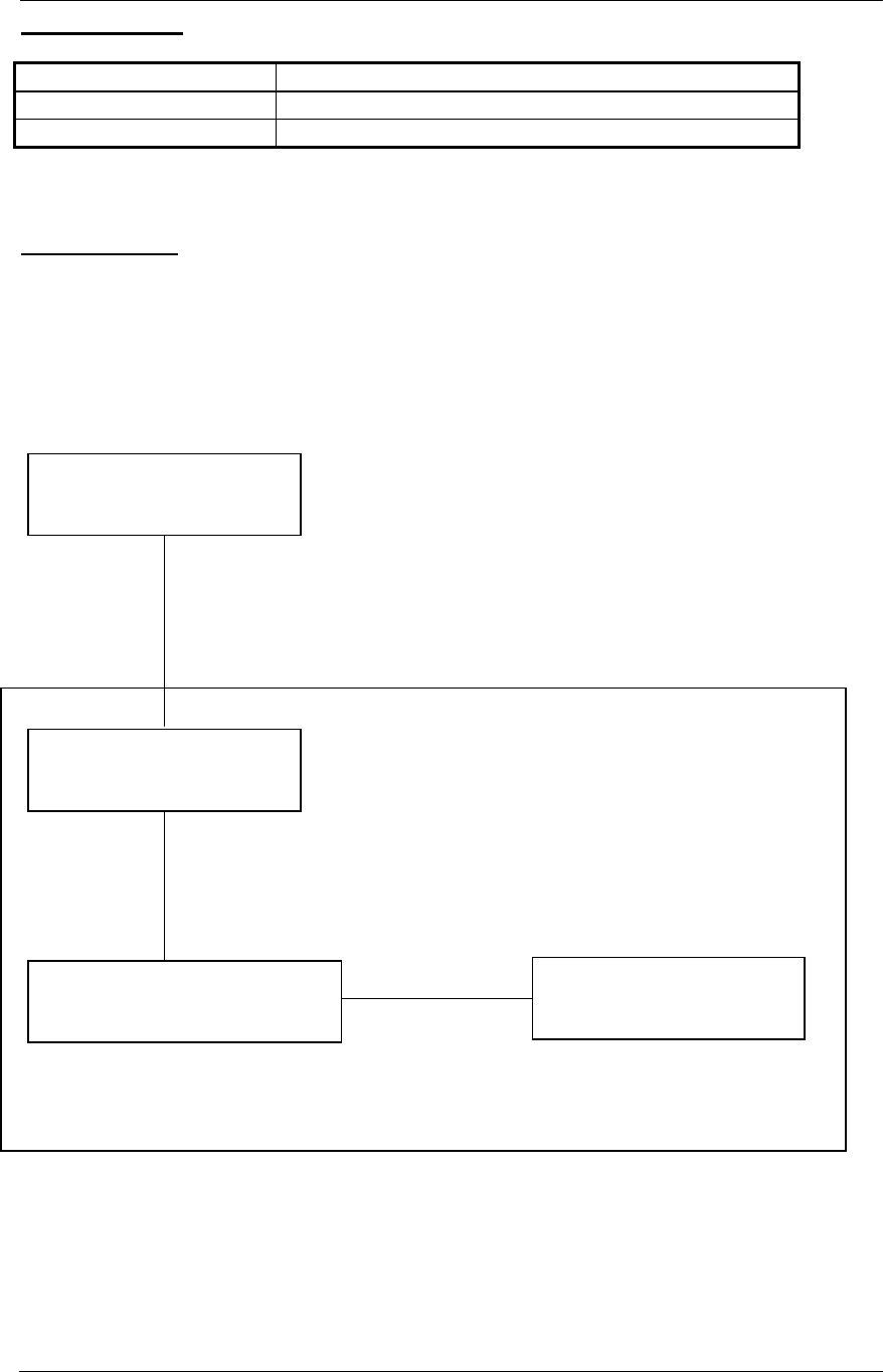
Block diagram
The immobilizer system consists of a control unit, the inductive antennas and the key.
To activate the system, sensors or push-buttons are located in the doors, in the trunk
lid and in the interior. Interaction with the vehicle is effected via the radio receiver in
the control module, which receives the messages from the key and transmits them
via the vehicle's CAN bus to the EZS.
Immobilzer
Control unit
with radio receiver
ID Key
Antennas in the doors, in the
trunk lid and in the bumper
Electronic ignition
starter switch
EZS
CAN bus
Wiring
harnes
s
125 kHz

SIEMENS VDO Automotive AG SV C BC P2 RF TG
FCC ID:KR55WK48089 IC:267T-5WK48089
File: D:\Postzula\Kunden\Mb\W221\FunctionalDiscription_W221.doc Page 4 of 4
Technical description
Carrier frequency: 125kHz ± 5kHz
Field strength: <42 dµA/m in 10 m
Modulation: ASK
Supply voltage: 13.5 V
Type of battery: car battery
Range: < 2.0 m
Duty Cycle
20 actuations of immobilizer system within 24 hours with a typical transmission time
of 0,08 seconds. 0.07 seconds / hour.
Transmission time T (on) 0.07 seconds / hour
Off time T (off) 3,599.93 seconds / hour
Duty Cycle: T (on) / T (on+off) x 100% = 0.07 / 3,600 x 100% = 0.002%
Label Design
Europe:
Siemens VDO
5WK4 8079
USA/CAN:
Siemens VDO
5WK48089
FCC ID:KR55WK48089
IC:267T-5WK48089
This device complies with part 15 of
the FCC Rules and RSS-210.
Operation is subject to the following
two conditions: (1) This device may not
cause harmful interference, and (2)
this device must accept interference
received, including interference that
may cause undesired operation.
NOTE:
Changes or modifications not expressly approved by the manufacturer could void the
user's authority to operate the equipment.

SIEMENS VDO Automotive AG SV C BC P2 RF TG
FCC ID:KR55WK48089 IC:267T-5WK48089
D:\Postzula\Kunden\Mb\W221\FunctionalDiscription_W221.doc Page 5 of 5
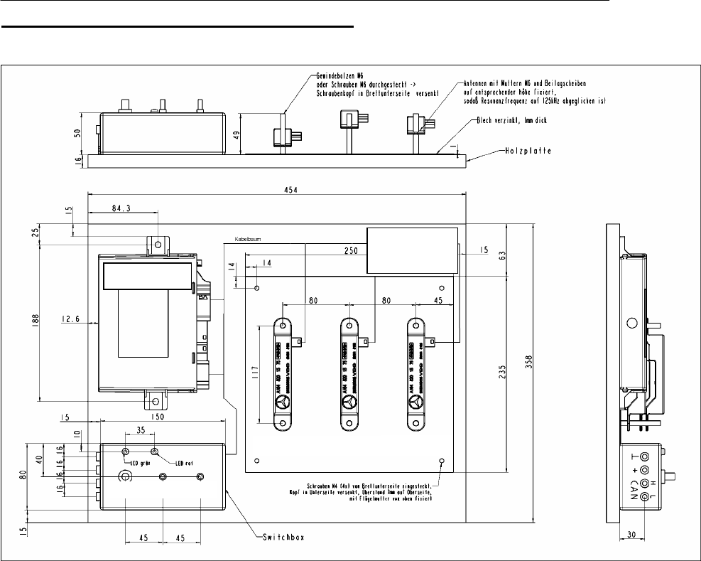
Functional description of the measurement system
The test setup comprises the following components:
- Control unit
- Induktive Ferrite antennas
- Board for radio homologation measurements (including Wiring harness)
- Key (normal Mode) to verify the function (if attached/required)
- Test box
SIEMENS VDO Automotive AG SV C BC P2 RF TG
FCC ID:KR55WK48089 IC:267T-5WK48089
D:\Postzula\Kunden\Mb\W221\FunctionalDiscription_W221.doc Page 6 of 6
Board for radio homologation measurement
Main
Int
Ext
Antenna Ext Antenna Int 1 Antenna Int 2
GND
GND
12V
Place ID-
Ke
y
here
Control unit

SIEMENS VDO Automotive AG SV C BC P2 RF TG
FCC ID:KR55WK48089 IC:267T-5WK48089
D:\Postzula\Kunden\Mb\W221\FunctionalDiscription_W221.doc Page 7 of 7
Functional description of the measurement system
The entire setup is supplied with power via the two banana jacks on the test box:
Banana jack, red : +12V DC
Banana jack, black : GND (ground)
The current input (in case of operation) is
min 0,3A/ max 0,8A av. ( min 1,5App/max 8App)
"Main" switch:
"Main" switch on: control unit is powered and the green LED is lighting
"Main" switch off: control module is unpowered
Switches "Ext" and "Int"
"Ext" on, "Int" off: selects functional test and test of emission of external antenna
"Ext" off, "Int" on: selects test of emission of internal antenna
"Ext" off, "Int" off: no mode selected
"Ext" on, "Int" on: no operation is possible when both switches are turned on
Functional test
1. Select "main" switch on
2. green LED is lighting
3. Turn the switch "ext" on ( make sure switch "int" is off )
4. Place the Id-key (normal Mode) within the red marked square on the board. It
will receive the inductive telegram and answer via RF.
5. If an RF telegram from the ID- key is received by the control module, the red
LED is flashing for 200ms.
6. As soon as the ID-Key is brought out of range (use 5m) the red LED will stop
flashing.
Test of emission of the exterior antenna
1. Select "main" switch on
2. Green LED is lighting
3. Turn the switch "ext" on ( make sure switch "int" is off )
4. The control module sends every 700ms an inductive telegram via the exterior
antenna
5. Measure the emission
6. After the test switch the switch "ext" and the main switch off.
Test of emission of the interior antennas
1. Select "main" switch on
2. Green LED is lighting
3. Switch the switch "int" on (make sure switch "ext" is off )
4. The control module sends every 700ms an inductive telegram via the interior
antenna
5. Measure the emission
6. After the test switch the switch "int" and the "main" switch off.