Continental Automotive Technologies 5WK48952 Inductive Keyless Vehicle System User Manual
Continental Automotive GmbH Inductive Keyless Vehicle System
user manual
Annex No.5
Functional Description
User Manual

SIEMENS VDO Automotive AG SV C BC P2 RF TG
FCC ID:KR55WK48952 IC:267T-5WK48952
File: I:\POSTZULA\Volvo\KVM\TechnicalDocu\Funktionsbeschreibung_KVM_v2.doc Page 1 of 5
Functional Description /
User Manual
of the
Siemens VDO
Keyless Vehicle Module
type 5WK4 8952

SIEMENS VDO Automotive AG SV C BC P2 RF TG
FCC ID:KR55WK48952 IC:267T-5WK48952
File: I:\POSTZULA\Volvo\KVM\TechnicalDocu\Funktionsbeschreibung_KVM_v2.doc Page 2 of 5
Functional Description
1. General functional description
This short system description gives an overview about the functionality of the Keyless
Vehicle (KV) system and from the Keyless Vehicle Module (KVM).
The vehicle and the Passive Key (PK) will communicate via challenge / response.
By any request the KVM sends a challenge via the respective Low Frequency (LF)
antennas with 125 kHz to the Passive Key. The PK’s within the detection range an-
swer with the identification code via Radio Frequency (RF) transmission. The
external RF Receiver sends the data from the received signal via serial link to the
KVM.
2. Passive entry, passive exit
2.1 Unlocking
With a valid PK within the outside detection range of the vehicle, the customer will be
able to open each door of the passenger compartment and the tailgate.
Woken up by pulling a door handle the KVM sends a challenge125 kHz via the cor-
responding inductive door handle antenna to the Passive Key. After receiving the
challenge data the Passive Key sends the response data via RF to the external re-
ceiver. If the identification code received is valid the KVM sends the unlock request
command via CAN-Bus to the Passenger Junction Box (PJB).
2.2 Locking
To lock the vehicle, the customer has to push the Lock Button mounted in any door
handle once and a valid PK has to be detected within the respective door handle de-
tection range.
3. Passive start/stop
The KV system will provide an inside detection range, which will cover the passenger
compartment.
SIEMENS VDO Automotive AG SV C BC P2 RF TG
FCC ID:KR55WK48952 IC:267T-5WK48952
File: I:\POSTZULA\Volvo\KVM\TechnicalDocu\Funktionsbeschreibung_KVM_v2.doc Page 3 of 5
3.1 Engine Start / Unlock of Steering Column
The starting action will be handled via a rotating Ignition Switch, which provides igni-
tion off, accessory, ignition on and crank position.
With a valid Passive Key within the interior detection range, the customer will be able
to start the engine after pushing the brake (automatic transmission) or pushing the
clutch pedal (manual transmission). After detection of a valid Passive Key the KVM
sends the release command to the Smart Steering Column Device (SSCD) via which
fulfills a mechanical release and permits the customer to rotate the Ignition Switch to
any position (ACC, Run, Start). Without detection of a valid PK, the Ignition Switch
and the steering column remains locked.
The Engine Control Unit receives authorization to start engine from the KVM via
CAN-Bus from the Cluster module.
3.2 Engine Stop / Lock of Steering Column
For Engine Stop the Ignition Switch must be rotated to ACC position.
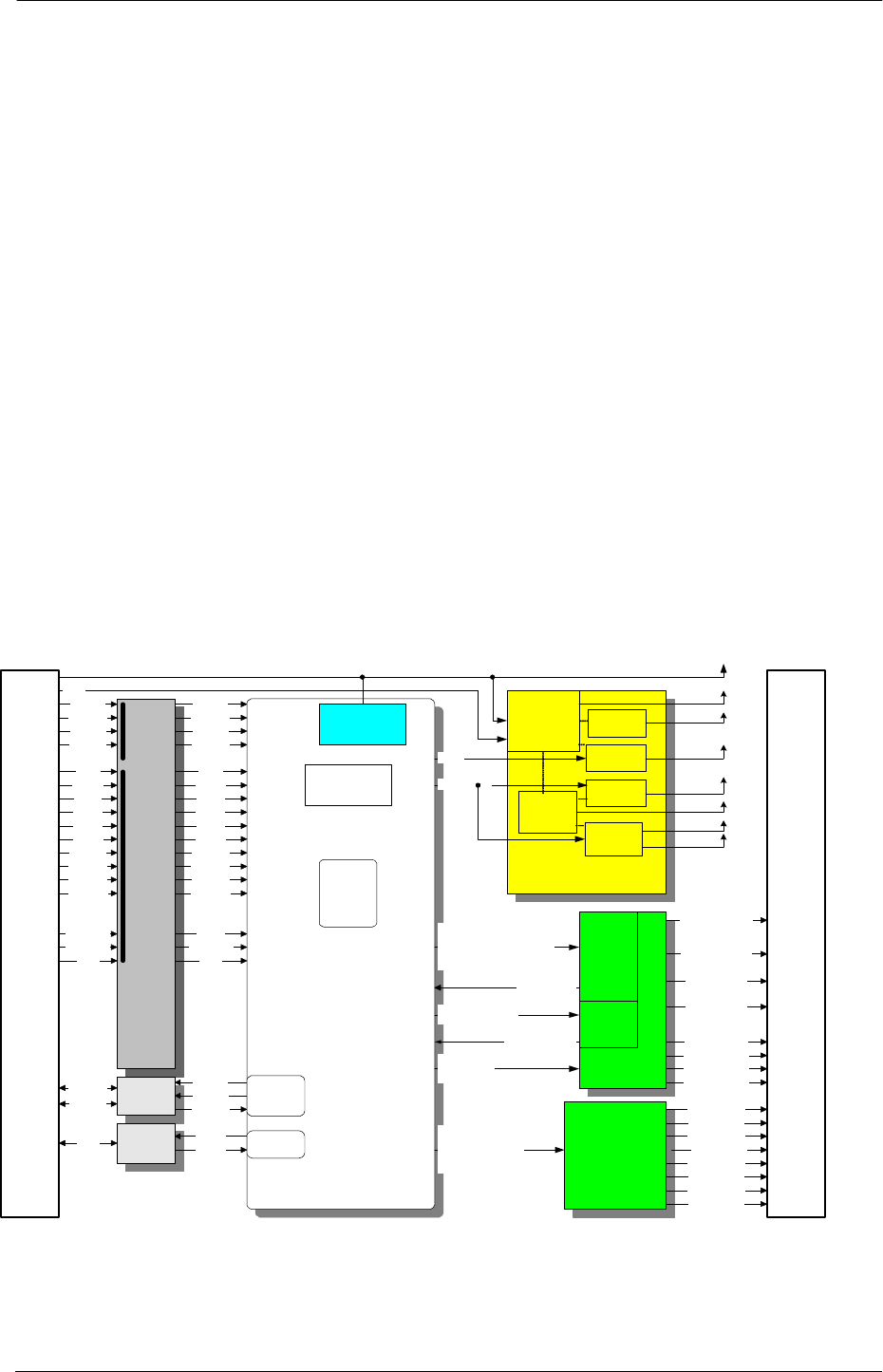
4. Block diagram Keyless Vehicle Module
Microcontroller
MC9S12B128
Stabilisation,
reverse
voltage
protection
Voltage
Regulator
Vcc
+12V
switched
Step up
regulator
KVM
Inputs
Release Motor
Latches
Relay
Matrix
Kl.30
Measurement
MS C AN
TJA1040
SRx
Interface
CAN TxD
CAN RxD
CAN High
CAN Low
SRx_
Serial
AD_Temperatur
Biterror
AD_Ant1, AD_Ant2
Ext_Trunk1_Ant +&-
Ex_Tr, Int_Tr,
Int1&2,
Left_A,Right_A
Power_LF, Power_on_LF
2MHz_Takt
Power 2, Power 1,Power0,
Power M1,Power M2,Power M3
TxD_To_LF_Stage
TxD RF
RxD RF
FL_RM_Latch+
LF-Stage
Antenna
Diagnostic
limitation
EN_CAN
FL_Latch+, FL_Latch-
FR_Latch+, FR_Latch-
RL_Latch+, RL_Latch-
RR_Latch+, RR_Latch-
CAN 2.0
Quarz 16 MHz
internal
Watchdog
Wake up
Polled
FL clutch
FR clutch
RL clutch
RR clutch
Brake
KeyIn_Start
SCI
RL unlock
FL lock
FL unlock
FR lock
FR unlock
RL lock
RR lock
RR unlock
Brake
Tailgate
Clutch
KeyIn_Start
FL clutch
FR clutch
RL clutch
RR clutch
RL unlock
FL lock
FL unlock
FR lock
FR unlock
RL lock
RR lock
RR unlock
Tailgate
Clutch
T.gate Lock GlassR
Kl. 31
Vcc
switched
Polling
Power_On_LF
Kl. 30
+12V_L
+16V
+12V_Ges
ch
VCCS
VCC
+20V
-7V
Ant_Diag1,Ant_Diag2
Ant_Diag3
Antenna
Relay Matrix
FL_RM_Latch-
FL_RM_Latch+
FL_RM_Latch-
FL_RM_Latch+
FL_RM_Latch-
FL_RM_Latch+
FL_RM_Latch-
Int_Trunk1_Ant +&-
Interior_Ant1 +&-
Interior_Ant3 +&-
FL_Door_Ant +&-
FR_Door_Ant +&-
RL_Door_Ant +&-
RR_Door_Ant +&-
Power Supply
KVM Connector
KVM Connector

SIEMENS VDO Automotive AG SV C BC P2 RF TG
FCC ID:KR55WK48952 IC:267T-5WK48952
File: I:\POSTZULA\Volvo\KVM\TechnicalDocu\Funktionsbeschreibung_KVM_v2.doc Page 4 of 5
5. List of variants
5WK48952 Keyless Vehicle Module (ECU)
5WK47894 LF antenna V3
5WK47893 LF antenna V2(housing variant)
5WK47891 LF antenna F2 (housing variant)
5WK47895 LF antenna V1 (housing variant)
6. Technical Data
Carrier frequency: 125 kHz +/- 1 kHz
Field strength: < 42 dBµA/m @ 10 m
Modulation: ASK
Supply voltage: 13 V
Battery type Car battery
Range: < 2 m
7. Typical Usage Pattern (for Europe only)
20 actuations of access control system within 24 hours with a typical transmission
time of 0.07 seconds / hour.
Transmission time TON 0.07 seconds / hours
Off time T OFF 3599.93 seconds / hours
Duty Cycle: TON / T (ON+OFF) x 100% = 0.07 / 3.600 x 100 % = 0.02 %

SIEMENS VDO Automotive AG SV C BC P2 RF TG
FCC ID:KR55WK48952 IC:267T-5WK48952
File: I:\POSTZULA\Volvo\KVM\TechnicalDocu\Funktionsbeschreibung_KVM_v2.doc Page 5 of 5
8. Label Design
Europe:
Siemens VDO
5WK4 8952
USA/CAN:
Siemens VDO
5WK48952
FCC ID:KR55WK48952
IC:267T-5WK48952
This device complies with part 15 of the
FCC Rules and RSS-210. Operation is
subject to the following two conditions: (1)
This device may not cause harmful inter-
ference, and (2) this device must accept
interference received, including interfer-
ence that may cause undesired operation.
NOTE:
Changes or modifications not expressly approved by the manufacturer could void the user's
authority to operate the equipment.