Continental Automotive Technologies 5WY7635 Tire Pressure Unit User Manual Manual
Continental Automotive GmbH Tire Pressure Unit Manual
Manual
Annex No.5
Technical Description
Users Manual
5WY7635

SIEMENS VDO Automotive SV C BC P2 RF
IC:267T-5WY7635 FCC ID:KR55WY7635
I:\POSTZULA\Tpms_TG\TG1B-VL2\Technische_Dokumente\functionnal description_5WY7635.doc 1 of 4
User Manual / Functional Description
of the
Siemens VDO
Tire Pressure Generation TG1B-VL2 wheel unit
Type
5WY7635
SIEMENS VDO Automotive SV C BC P2 RF
IC:267T-5WY7635 FCC ID:KR55WY7635
I:\POSTZULA\Tpms_TG\TG1B-VL2\Technische_Dokumente\functionnal description_5WY7635.doc 2 of 4
1.1. SYSTEM OVERVIEW
The TG1B-VL2 is a pressure sensor for Tire Pressure Monitoring System (TPMS)
application.
By several measurements and RF transmission, the driver is informed about the air
pressure in his vehicle wheels.
The following is a list of the wheel unit (WU) functions:
• Pressure measurement
• Temperature measurement
• Motion measurement (centrifugal acceleration)
• Battery status
• Radio frequency RF emission
• Low Frequency LF reception
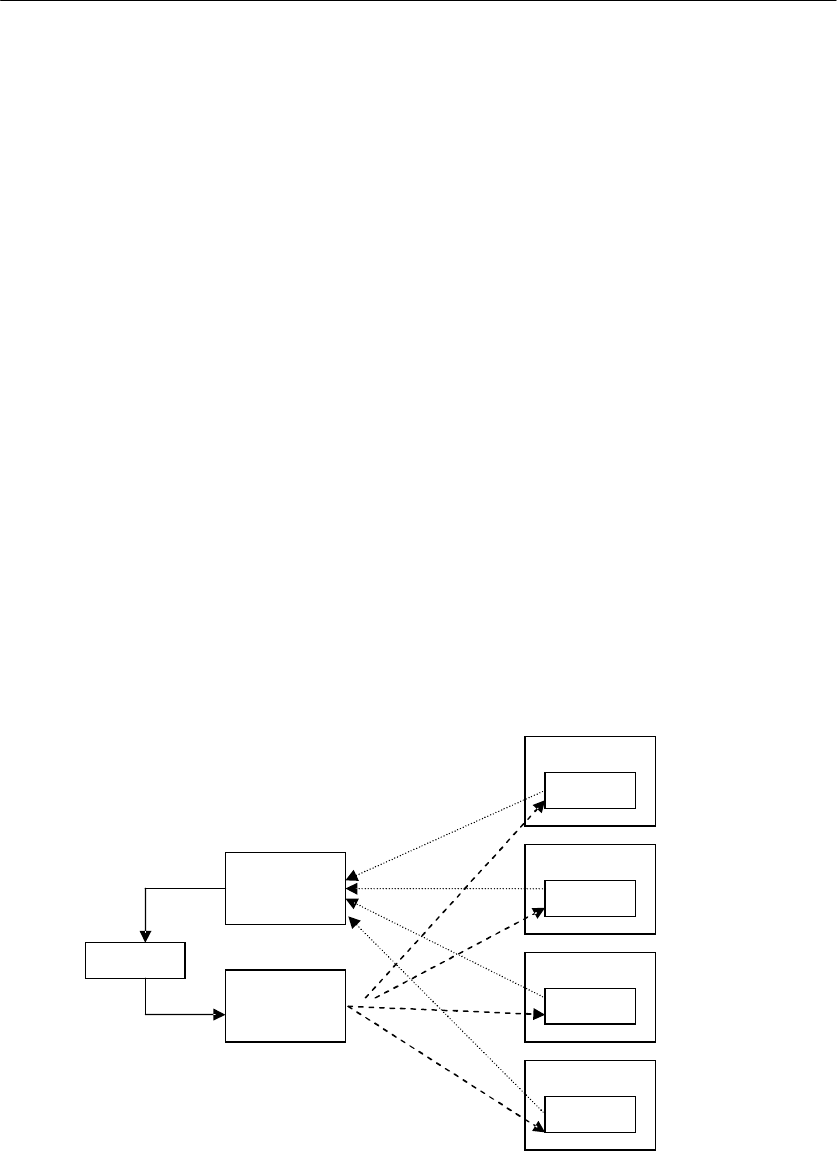
The system is made of an embedded WU that measures some parameters inside the
tire and transmits them by RF at 315 MHz to a central unit (TGR) in the vehicle. In
some cases, the TGR can trigger a RF emission from the WU by LF signal.
LF triggering is made by some specific LF drivers and antennas. RF reception is
made by one antenna linked to the TGR. LF triggering is only used in case of axle
localization.
The WU is mounted inside the wheels, fixed to the rim, which is also a part of the
System.
TGR
Aerial
315 Mhz
MHz
Aerial
LF
Wheel1
WU1
Wheel2
WU2
Wheel3
WU3
Wheel4
WU4

SIEMENS VDO Automotive SV C BC P2 RF
IC:267T-5WY7635 FCC ID:KR55WY7635
I:\POSTZULA\Tpms_TG\TG1B-VL2\Technische_Dokumente\functionnal description_5WY7635.doc 3 of 4
Rim WU
Tire
It is made of a PCB that supports the electronic hardware encapsulated inside a box
and polyurethane foam. It is self-powered by a battery and includes all systems for
measurements (pressure, temperature, centrifugal acceleration, and battery status),
RF emission and LF reception.
Theory of Operation
The sensor function is to provide to the receiver by RF frames the state of pressure
of the air in each one of the four tires of the car. The information given in the RF
frame indicates exactly the state of the car (rotating wheel or not) and the state of the
pressure in the tires.
At any time, the sensor must be able to detect some changes of the wheel behavior.
When the motion indicator is activated, the sensor enters the rotating mode. When
the motion indicator is deactivated, the sensor enters the interim mode for maximum
half an hour. During this period, the vehicle car return in rotating mode if it restarts
before the end of the 30 minutes stopped period or after 30 minutes time in interim
mode, the sensor goes automatically in stationary mode until it restarts and goes in
rotating mode.
SIEMENS VDO Automotive SV C BC P2 RF
IC:267T-5WY7635 FCC ID:KR55WY7635
I:\POSTZULA\Tpms_TG\TG1B-VL2\Technische_Dokumente\functionnal description_5WY7635.doc 4 of 4
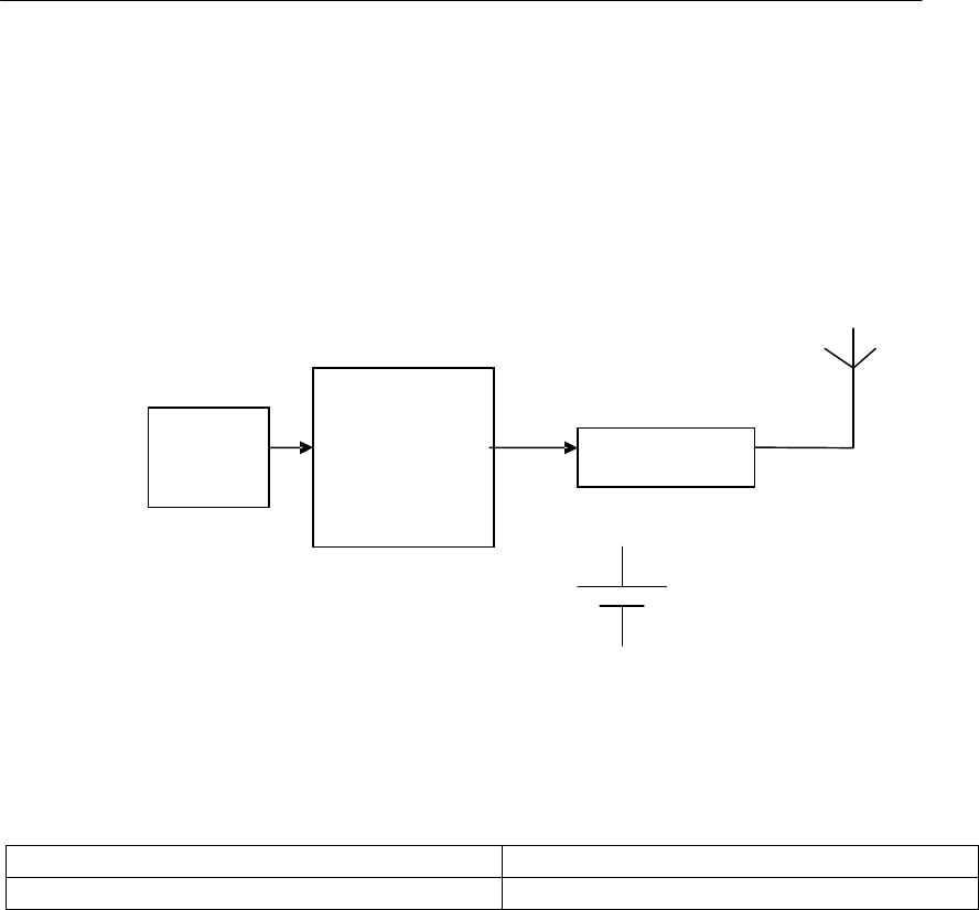
1.2. BLOCK DIAGRAM
The block diagram below shows the main electronic units of the wheel unit:
1.3. VARIANTS
Siemens type designation Remarks
5WY7635 Transmitter 315 MHz
1.4. TYPICAL USAGE PATTERN
One burst of 4 frames of 10.41ms per minute
=> in one hour =4*0.0104*60=2.5 seconds of transmission duration.
Transmitter ON 2.5 seconds / hour
Transmitter OFF 3597.5 seconds / hour
Duty Cycle: TON / T (ON+OFF) x 100% = 2.5 / 3600 x 100 % = 0.069 %
Pressure,
temperature,
acceleration,
Sensor and
µcontroller
RF emitter
Lithium
battery
CR2450
LF
receiver

SIEMENS VDO Automotive SV C BC P2 RF
IC:267T-5WY7635 FCC ID:KR55WY7635
I:\POSTZULA\Tpms_TG\TG1B-VL2\Technische_Dokumente\functionnal description_5WY7635.doc 5 of 4
1.5. TECHNICAL DESCRIPTION VARIANT 5WY7635
Carrier Frequency : 315 MHz
Field strength : < 87 dBµV/m @ 3m (CW mode)
Frequency shift : ± 35 kHz target value (± 30 kHz min to ± 50 kHz max)
Number of channel : 1
Type of modulation : FSK-ASK
Antenna : Integral
Voltage supply : 1 lithium battery 3V (CR2450)
Voltage supply range : 2.1 up to 3.2 V
1.6. LABEL DESIGN CANADA, USA, MEXICO
Siemens VDO
5WY7635
FCC ID:KR55WY7635
IC:267T-5WY7635
owner manual: warning statement
This device complies with part 15 of the FCC Rules and RSS-210. Operation is
subject to the following two conditions: (1) This device may not cause harmful
interference, and (2) this device must accept interference received, including
interference that may cause undesired operation.
Note:
Changes or modifications not expressly approved by the manufacturer could void the
user's authority to operate the equipment.