Continental Automotive Technologies FLEXCM FLEXCM User Manual Operational Deskription
Continental Automotive GmbH FLEXCM Operational Deskription
User Manual

Installation Instruction
Designed b
Anton Kolar
Date
29.06.2017
Department
I CVAM TTS LRH
Released by
Date
Department
Designation
Installation Instruction
Document
Version
Pages
1/ 19
Continental Automotive GmbH
Installation Instruction
Autor:
Anton Kolar, I CVAM RD TTS SY1
Continental Automotive GmbH
Heinrich-Hertz-Straße 45
D-78052 Villingen-Schwenningen
Postfach1640
D-78006 Villingen-Schwenningen
Tel: +49 7721 / 67 – 3128
Fax: +49 7721 / 67 - 793128
E-Mail: Anton.Kolar@continental-corporation.com
Revision
Release
1.2

Installation Instructions
Designed b
Anton Kolar
Date
29.06.2017
Department
I CVAM RD TTS SY1
Released by
Dr. M.Grüner
Date
Department
ICVAMTTSLRH
Designation
Installation Instruction
Document
Version
Pages
2/ 19
Continental Automotive GmbH
1 History
Rev.
Date
Status
Author
Remarks
1.0
29.06.2017
Final
Anton Kolar
1.1
26.07.2017
Final
Dr. Marion Grüner
Update after review from the test lab
“Seimic”
1.2
03.08.2017
Final
Dr. Marion Grüner
Update after review from the test lab
“Seimic” about the usage of the antennas

Installation Instructions
Designed b
Anton Kolar
Date
29.06.2017
Department
I CVAM RD TTS SY1
Released by
Dr. M.Grüner
Date
Department
ICVAMTTSLRH
Designation
Installation Instruction
Document
Version
Pages
3/ 19
Continental Automotive GmbH
1 History ............................................................................................................................................. 2
2 Delivery content and general note .................................................................................................. 4
3 Connection Overview and DIP Switches .......................................................................................... 6
4 Location of LEDs .............................................................................................................................. 7
5 Connection diagram ........................................................................................................................ 8
5.1 Main connector ....................................................................................................................................... 8
5.2 8-pin and 6-pin interface connectors ...................................................................................................... 9
5.3 External GNSS antenna connector ...................................................................................................... 10
5.4 External WLAN antenna connector ...................................................................................................... 10
5.5 External GSM antenna connector ........................................................................................................ 10
5.6 USB 2.0 OTG connector ....................................................................................................................... 10
6 General Safety Notes ..................................................................................................................... 11
7 Installation Requirements ............................................................................................................. 13
8 Required FLEX CM Telematics Unit connections ........................................................................... 14
9 FLEX CM Telematics Unit installation locations ............................................................................ 14
10 Installation Position ................................................................................................................... 15
11 Installing the FLEX CM Telematics Unit ..................................................................................... 16
12 Setting the termination resistance ............................................................................................ 17
13 GNSS recording .......................................................................................................................... 18
14 Technical data and requirements .............................................................................................. 19

Installation Instructions
Designed b
Anton Kolar
Date
29.06.2017
Department
I CVAM RD TTS SY1
Released by
Dr. M.Grüner
Date
Department
ICVAMTTSLRH
Designation
Installation Instruction
Document
Version
Pages
4/ 19
Continental Automotive GmbH
2 Delivery content and general note
Delivery Content
FLEX CM Telematicss Unit
Connection cable (optional)
GNSS antenna (optional)
Installation Instruction
_________________________________________________________
Note: Please be aware, the installation location of the device has to be in
a minimum distance of 20cm of the head of a human.
_________________________________________________________
_________________________________________________________
Note:
FCC compliance statement
This device complies with part 15 of the FCC Rules. Operation is subject
to the following two conditions: (1) This device may not cause harmful
interference, and (2) this device must accept any interference received,
including interference that may cause undesired operation.
_________________________________________________________
_________________________________________________________
Note:
Non-modification warning statement
Any Changes or modifications not expressly approved by the party
responsible for compliance could void the user's authority to operate the
equipment.
_________________________________________________________

Installation Instructions
Designed b
Anton Kolar
Date
29.06.2017
Department
I CVAM RD TTS SY1
Released by
Dr. M.Grüner
Date
Department
ICVAMTTSLRH
Designation
Installation Instruction
Document
Version
Pages
5/ 19
Continental Automotive GmbH
Note:
Usage of antennas
Do NOT substitute any antenna for the one supplied by or recommended
by the manufacturer. Substituting an antenna may expose a person or
persons to harmful radio frequency radiation. Contact the manufacturer
for further instructions.
_______________________________________________________
Installation Instructions
Designed b
Anton Kolar
Date
29.06.2017
Department
I CVAM RD TTS SY1
Released by
Dr. M.Grüner
Date
Department
ICVAMTTSLRH
Designation
Installation Instruction
Document
Version
Pages
6/ 19
Continental Automotive GmbH
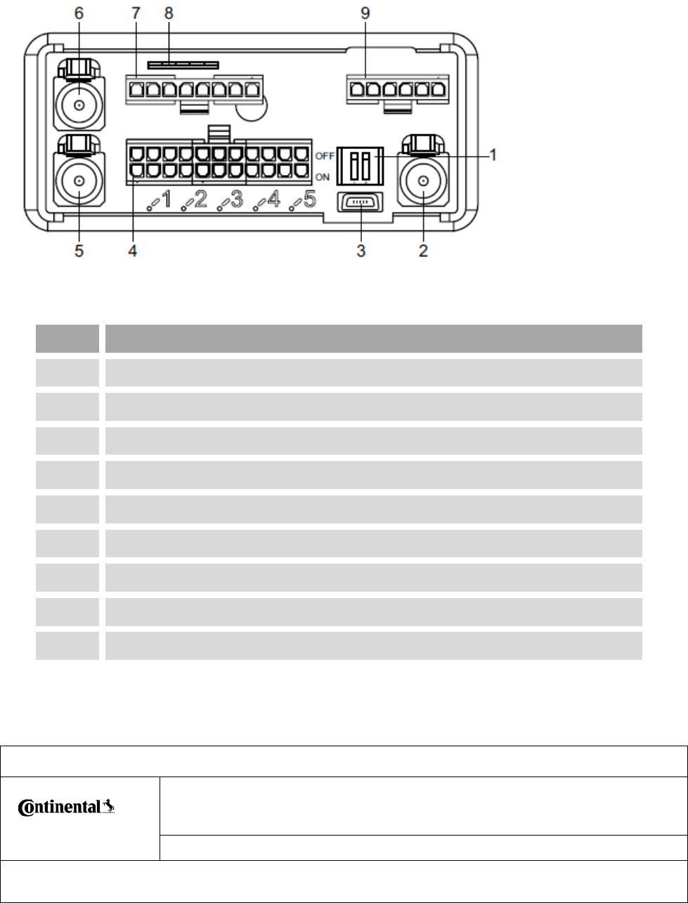
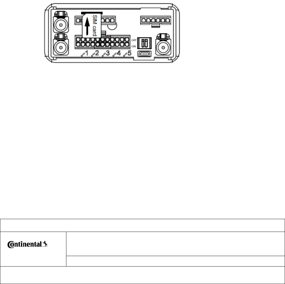
3 Connection Overview and DIP Switches
Item
Designation
1
DIP switches for CAN3 high / low termination setting (OFF / ON)
2
WLAN antenna connector
3
Mini USB connector
4
Main connector (i.e. to connect a DTCO® 1381)
5
GPS antenna connector
6
GSM antenna connector
7
8-pin interface connector
8
Micro SIM card
9
6-pin interface connector
Installation Instructions
Designed b
Anton Kolar
Date
29.06.2017
Department
I CVAM RD TTS SY1
Released by
Dr. M.Grüner
Date
Department
ICVAMTTSLRH
Designation
Installation Instruction
Document
Version
Pages
7/ 19
Continental Automotive GmbH
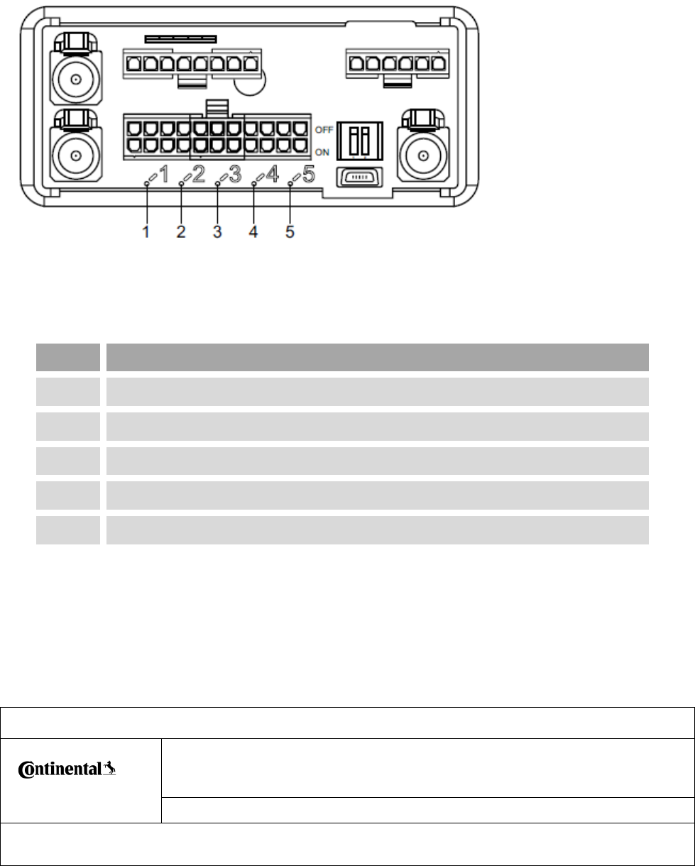
4 Location of LEDs
LED
Designation
1
Green; Free programmable LED
2
Red; during boot / Free programmable LED
3
Green; Free programmable LED
4
Green; Free programmable LED
5
Green; Free programmable LED
Installation Instructions
Designed b
Anton Kolar
Date
29.06.2017
Department
I CVAM RD TTS SY1
Released by
Dr. M.Grüner
Date
Department
ICVAMTTSLRH
Designation
Installation Instruction
Document
Version
Pages
8/ 19
Continental Automotive GmbH
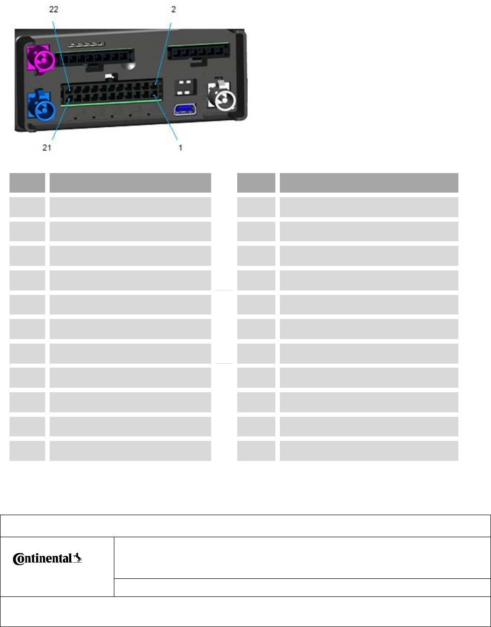
5 Connection diagram
5.1 Main connector
Item
Designation
Item
Designation
1
Terminal 31
12
CAN 3 high
2
Terminal 30
13
Ground
3
Ground (RS232)
14
D8
4
Terminal 15
15
Ground
5
Ground
16
Digital Input 1
6
Not connected
17
Digital Output High Side
7
Ground
18
Not connected
8
Not connected
19
Ground
9
Ground
20
Not connected
10
CAN 3 low
21
RS232 TX line
11
Ground
22
RS232 RX line
Installation Instructions
Designed b
Anton Kolar
Date
29.06.2017
Department
I CVAM RD TTS SY1
Released by
Dr. M.Grüner
Date
Department
ICVAMTTSLRH
Designation
Installation Instruction
Document
Version
Pages
9/ 19
Continental Automotive GmbH
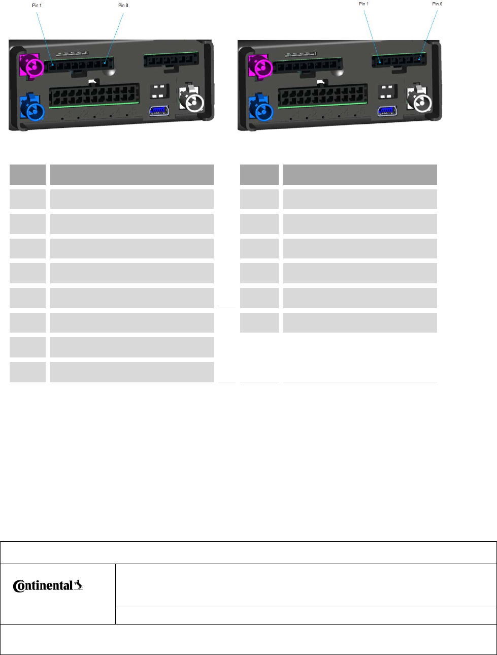
5.2 8-pin and 6-pin interface connectors
Item
Designation
Item
Designation
1
CAN 1 high
1
CAN 2 high
2
CAN 1 low
2
CAN 2 low
3
Ground
3
Ground
4
Digital Input 2
4
Digital Input 5
5
Digital Input 3
5
Digital Input 6
6
Digital Input 4
6
Digital Output Low Side
7
Analog Input 1
8
Ground
Installation Instructions
Designed b
Anton Kolar
Date
29.06.2017
Department
I CVAM RD TTS SY1
Released by
Dr. M.Grüner
Date
Department
ICVAMTTSLRH
Designation
Installation Instruction
Document
Version
Pages
10/ 19
Continental Automotive GmbH
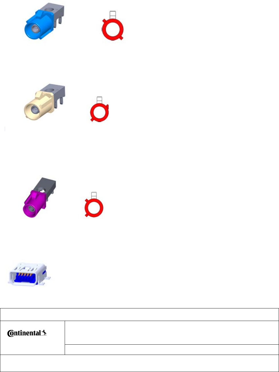
5.3 External GNSS antenna connector
5.4 External WLAN antenna connector
5.5 External GSM antenna connector
5.6 USB 2.0 OTG connector
Installation Instructions
Designed b
Anton Kolar
Date
29.06.2017
Department
I CVAM RD TTS SY1
Released by
Dr. M.Grüner
Date
Department
ICVAMTTSLRH
Designation
Installation Instruction
Document
Version
Pages
11/ 19
Continental Automotive GmbH
6 General Safety Notes
_________________________________________________________
Warning: Risk of electric shock
All work on the electrical system must only be carried out by a specialist workshop.
___________________________________________________________________
___________________________________________________________________
Warning: Danger of short circuits
Bear in mind that during all installation work (especially when working on the
vehicle’s electrical system), the vehicle manufacturer’s instructions must be adhered
to.
___________________________________________________________________
___________________________________________________________________
Warning: Before removing the connection terminals from the battery, observe the
following points:
• Switch off all electrical consumers.
• Disconnect the negative battery terminal before the positive battery terminal.
Warning: Secure all power cables in accordance with the guidelines.
___________________________________________________________________
Warning: Danger of explosion
When loading and unloading hazardous goods onto / from ADR vehicles and in
environments that are at risk of explosion, the DTCO® 1381 front interface must be
closed, i. e.
• The FLEX CM Telematics Unit power circuit must be switched off via the
vehicle’s master switch.
• There must be no plug connections to the DTCO® 1381 and no data being
downloaded.
___________________________________________________________________

Installation Instructions
Designed b
Anton Kolar
Date
29.06.2017
Department
I CVAM RD TTS SY1
Released by
Dr. M.Grüner
Date
Department
ICVAMTTSLRH
Designation
Installation Instruction
Document
Version
Pages
12/ 19
Continental Automotive GmbH
___________________________________________________________________
Caution: Do not run the cables over sheet metal or plastic parts with sharp edges.
___________________________________________________________________
___________________________________________________________________
Caution: Do not bend the cables.
___________________________________________________________________
Caution: Do not install the FLEX CM Telematics Unit near shelves or moving parts,
e.g. airbags and covers.
___________________________________________________________________
___________________________________________________________________
Note: Installation and setup work may only be carried out by service technicians.
___________________________________________________________________
___________________________________________________________________
Note: In addition to the above instructions, please also note the Service Information
documents on the VDO Extranet at
http://extranet.vdo.com or ask your service partner.
___________________________________________________________________
___________________________________________________________________
Note: Please observe the rules and regulations (which apply in your country) for
accident prevention and the recognized specialist technical rules for safe and
professional working.
___________________________________________________________________
Installation Instructions
Designed b
Anton Kolar
Date
29.06.2017
Department
I CVAM RD TTS SY1
Released by
Dr. M.Grüner
Date
Department
ICVAMTTSLRH
Designation
Installation Instruction
Document
Version
Pages
13/ 19
Continental Automotive GmbH
7 Installation Requirements
___________________________________________________________________
Note: Use the overview on page 2 to check that all the items in the FLEX CM
Telematics Unit package are present.
___________________________________________________________________
The FLEX CM Telematics Unit can only collect data and communicate with other
devices if:
• A SIM card is inserted and a contract for GPRS data transfer has been
concluded.
• The GPS antenna has already been properly installed in the vehicle and the
connection cable has been run to the FLEX CM Telematics Unit’s installation
location (see the following note).
___________________________________________________________________
Note: For detailed information on how to install the GPS antenna, please refer to the
enclosed manufacturer’s instructions.
___________________________________________________________________

Installation Instructions
Designed b
Anton Kolar
Date
29.06.2017
Department
I CVAM RD TTS SY1
Released by
Dr. M.Grüner
Date
Department
ICVAMTTSLRH
Designation
Installation Instruction
Document
Version
Pages
14/ 19
Continental Automotive GmbH
8 Required FLEX CM Telematics Unit connections
• Connection to the power supply
• Connection to the ignition signal and to ground
• Connection to the vehicle via a CAN interface
9 FLEX CM Telematics Unit installation locations
You can choose the installation location. We recommend, however, that you install
the device into the dashboard.
Please also note the following warnings and instructions:
___________________________________________________________________
Warning: Do not cover any defroster vents on the dashboard with the FLEX CM
Telematics Unit and note any other devices (in the background) before fixing the
device.
___________________________________________________________________
___________________________________________________________________
Note: The driver must have a sufficient field of vision under all operating and weather
conditions when the device is mounted on the dashboard.
___________________________________________________________________
___________________________________________________________________
Note: When installing the device observe a safety distance of at least 25 cm between
the device and any person travelling in the vehicle.
___________________________________________________________________
___________________________________________________________________
Note: If the FLEX CM Telematics Unit is to be installed in locations where higher
requirements must be met (presence of humidity, vapour, oil, etc.), the device should
be installed with the connection strip facing down.
___________________________________________________________________
___________________________________________________________________
Installation Instructions
Designed b
Anton Kolar
Date
29.06.2017
Department
I CVAM RD TTS SY1
Released by
Dr. M.Grüner
Date
Department
ICVAMTTSLRH
Designation
Installation Instruction
Document
Version
Pages
15/ 19
Continental Automotive GmbH
Note: Fix the cables at short intervals (approx. every 500 mm) so that they do not
vibrate.
___________________________________________________________________
___________________________________________________________________
Note: When installing into the dashboard, make sure that the FLEX CM Telematics
Unit can be removed quickly, e. g. to carry out a manual firmware upgrade or for
installing a different antenna.
Tip: Put the sticker (included in the package) over the DIP switch and USB interface
openings in the housing to prevent any foreign matter getting into the device.
___________________________________________________________________
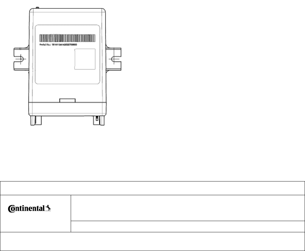
10 Installation Position
To fulfill the IP class of the device, the device has to be installed that the opening for
connectors/cables are on bottom side.

Installation Instructions
Designed b
Anton Kolar
Date
29.06.2017
Department
I CVAM RD TTS SY1
Released by
Dr. M.Grüner
Date
Department
ICVAMTTSLRH
Designation
Installation Instruction
Document
Version
Pages
16/ 19
Continental Automotive GmbH
11 Installing the FLEX CM Telematics Unit
Requirements
• Installation location determined
• Power supply and CAN interface cables installed
• GPS antenna and connection cable installed
___________________________________________________________________
Note: Please observe the notes from page 10 to page 14.
___________________________________________________________________
1. Fix the FLEX CM Telematics Unit in the installation location. Screw on the
FLEX CM Telematics Unit with two screws.
The device can be fixed by screws M5.
Washer or screw with flange to be used.
Torque: max. Torque 6,5Nm.
2. Connect the power cable and CAN interface cable to the relevant connections
in the vehicle.
___________________________________________________________________
Please note: the manufacturer’s instructions when doing this (see the figures on
pages 7 to 9 and 14).
___________________________________________________________________

Installation Instructions
Designed b
Anton Kolar
Date
29.06.2017
Department
I CVAM RD TTS SY1
Released by
Dr. M.Grüner
Date
Department
ICVAMTTSLRH
Designation
Installation Instruction
Document
Version
Pages
17/ 19
Continental Automotive GmbH
12 Setting the termination resistance
Delivery condition: The CAN interface termination resistors are disabled (the switches
are set to OFF and point in the direction of the top interface connector).
The DIP switches for setting the CAN termination resistance on the FLEX CM
Telematics Unit are located above the mini USB connection (see page 4).
___________________________________________________________________
Note: The DIP switches only have to be set when connecting the FLEX CM
Telematics Unit using the 22-pin main connector (see page 4).
___________________________________________________________________
___________________________________________________________________
Caution: When using the FLEX CM Telematics Unit together with the CAN interface,
the two termination resistors must be enabled, if the resistors terminate the CAN line
(the switches set to ON and point in the direction of the mini USB connector).
___________________________________________________________________
___________________________________________________________________
Note: When using CAN interfaces on the 6-pin or 8-pin plug, termination resistors are
not pre-installed.
___________________________________________________________________

Installation Instructions
Designed b
Anton Kolar
Date
29.06.2017
Department
I CVAM RD TTS SY1
Released by
Dr. M.Grüner
Date
Department
ICVAMTTSLRH
Designation
Installation Instruction
Document
Version
Pages
18/ 19
Continental Automotive GmbH
13 GNSS recording
If you want the FLEX CM Telematics Unit to record GNSS data, you must connect
the external antenna (see page 4).
___________________________________________________________________
Note: For detailed information on how to install the GNSS antenna, please refer to
the enclosed manufacturer’s instructions.
___________________________________________________________________
___________________________________________________________________
Note: The GNSS antenna has to be mounted at a distance of at least 20 cm distance
to any other GNSS antenna (if available).
___________________________________________________________________

Installation Instructions
Designed b
Anton Kolar
Date
29.06.2017
Department
I CVAM RD TTS SY1
Released by
Dr. M.Grüner
Date
Department
ICVAMTTSLRH
Designation
Installation Instruction
Document
Version
Pages
19/ 19
Continental Automotive GmbH
14 Technical data and requirements
FLEX CM Telematics Unit
Dimensions
L 130 x W 116 x H 40 mm
Power supply
9 V - 32 V
Power
consumption
Active mode: RMS consumption of 500 mA at 12 V
Peak consumption: 2 A at 12 V
Sleep mode: up to 50 mA at 12 V
(depending on the configuration)
Temperature
range
Storage: -40 °C to 85 °C
Operating: -40 °C to 70 °C
Backup battery
none
Protection class
IP54 on 5 sides
IP42 on 1 side if installed with the connection strip facing
down
In-line fuse
protection
5 A (into the harness, if in delivery)
USB
Type 1.1 and 2.0