Continental Automotive Technologies S120123007 Tire pressure unit User Manual
Continental Automotive GmbH Tire pressure unit Users Manual
Users Manual

SIEMENS VDO Automotive SV C BC P2 RF
IC:267T-20123007 FCC ID:KR5S120123007
File: I:\POSTZULA\Tpms_TG\TG1B_GM\Technische_Doku\FunctionalDescription_S120123007A0.doc 1 of 4
User Manual / Functional Description
of the
Siemens VDO
Tire Pressure Generation 1B-EP wheel unit
Type
S 120 123 007

SIEMENS VDO Automotive SV C BC P2 RF
IC:267T-20123007 FCC ID:KR5S120123007
File: I:\POSTZULA\Tpms_TG\TG1B_GM\Technische_Doku\FunctionalDescription_S120123007A0.doc 2 of 4
1. SYSTEM OVERVIEW
The tire pressure monitoring system (referred as TG for Tire Guard) consists of
the following units:
- Tire guard transmitter type S 120 123 007 which includes an integrated
pressure, temperature and acceleration sensor and a RF transmitter.
- RF receiver unit which includes a receiver (not described in this document)
The Tire Guard system monitors a vehicle's tire pressure whilst driving or
stationary. An electronic unit (wheel unit) inside each tire, mounted to the valve
stem, periodically measures the actual tire pressure. By means of RF
communication, this pressure information is transmitted to the RF
receiver/decoder.
In stationary mode, the pressure, temperature and acceleration are measured
about every minute and emission of RF frames occurs only if pressure variation,
higher than a threshold, is detected (leakage detection).
When the vehicle starts moving, the Tire Guard transmitter enters the driving
mode. Then the wheel unit measures and transmits data every minute. The
wheel unit will remain in driving mode for a period of 15 minutes after the vehicle
is stopped. After this period has elapsed, the wheel unit returns to stationary
mode.
If, during any measurement period in driving mode, the pressure leakage is
detected (difference compared to the last transmitted pressure value), a re-
measure will occur after 1s (during 8s) taking in account the latest pressure value
emitted as reference value. If the pressure continues changing, an additional
transmission will be sent.
The circuit within the wheel unit monitors the battery every time a pressure
measurement is taken. A “Low Battery” function code will be sent when the
battery voltage within the wheel unit is below a pre-selected level.
SIEMENS VDO Automotive SV C BC P2 RF
IC:267T-20123007 FCC ID:KR5S120123007
File: I:\POSTZULA\Tpms_TG\TG1B_GM\Technische_Doku\FunctionalDescription_S120123007A0.doc 3 of 4
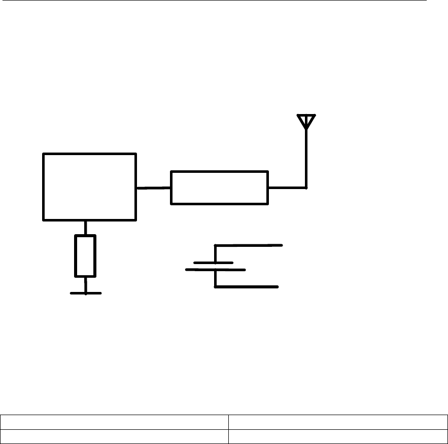
2. BLOCK DIAGRAM
The block diagram below shows the main electronic units of the wheel unit:
3V
LITHIUM
BATTERY
Learning coil
RF CIRCUIT
ANTENNA
Pressure,
temperature,
acceleration
sensor and
µcontroller
3. VARIANTS
Siemens type designation Remarks
S 120 123 007 Transmitter 315 MHz
4. TYPICAL USAGE PATTERN
72 burst in 24 hours because 1 burst is emitted every minute in normal condition.
0.014 seconds per frame and 6 frame per burst
• total transmission duration of 6.2 seconds within 24 hours
Transmitter ON 0.26 seconds / hour
Transmitter OFF 3599.74 seconds / hour
Duty Cycle: TON / T (ON+OFF) x 100% = 0.26 / 3600 x 100 % = 0.007 %

SIEMENS VDO Automotive SV C BC P2 RF
IC:267T-20123007 FCC ID:KR5S120123007
File: I:\POSTZULA\Tpms_TG\TG1B_GM\Technische_Doku\FunctionalDescription_S120123007A0.doc 4 of 4
5. TECHNICAL DESCRIPTION
Carrier frequency: 315 MHz
Frequency shift: None
Number of channels: 1
Method of frequency generation: PLL
Type of modulation: ASK
Rated Output Power: < 10 mW
Antenna: External (Valve antenna)
Voltage supply: 1 Lithium battery 3V (CR2450)
Voltage supply range : 2,1 up to 3,2V
6. LABEL DESIGN USA, CANADA
Siemens VDO
S120123007
FCC ID:KR5S120123007
IC:267T-20123007
owner manual: warning statement
This device complies with part 15 of the FCC Rules and RSS-210. Operation is
subject to the following two conditions: (1) This device may not cause harmful
interference, and (2) this device must accept interference received, including
interference that may cause undesired operation.
Note:
Changes or modifications not expressly approved by the manufacturer could void
the user's authority to operate the equipment.