Continental Automotive 5WK49385 Inductive System, Vehicle Immobilizer User Manual
Continental Automotive GmbH Inductive System, Vehicle Immobilizer
user manual

Annex No.5
Page 1 of 5
Functional description

SIEMENS VDO Automotive SV C BC P2 RF
IC:267T-5WK49385 FCC ID:KR5 5WK49385
Page 1 of 4
Functional Description
Homologation Board
SKE ECU
5WK49385
SIEMENS VDO Automotive SV C BC P2 RF
IC:267T-5WK49385 FCC ID:KR5 5WK49385
Page 2 of 4
1.1. BLOCKDIAGRAM HOMOLOGATION BOARD

SIEMENS VDO Automotive SV C BC P2 RF
IC:267T-5WK49385 FCC ID:KR5 5WK49385
Page 3 of 4
1.2. FUNCTIONAL DESCRIPTION OF HOMOLOGATION BOARD
The homologation board is performed to activate different functions of the SKE
Module
via Software. You must only connect the plus and the minus plug to a battery (normal
operating voltage is Vbat = 13,5 V ± 0.2 V) or a power supply and the ECU starts
sending the LF telegrams in the following order:
Int. group => int. front > int. rear > Int. trunk > Int. front ...
Ext. group => ext.FL > ext. FR > ext. bumper > ext.FL ...
Every group has a time slot of 150ms. After this time, the Software changes
automatically the sending group.
In case of malfunction, disconnect the power supply, wait 3 seconds and connect it
again.
The test will be done with SKE for J61A (v01)
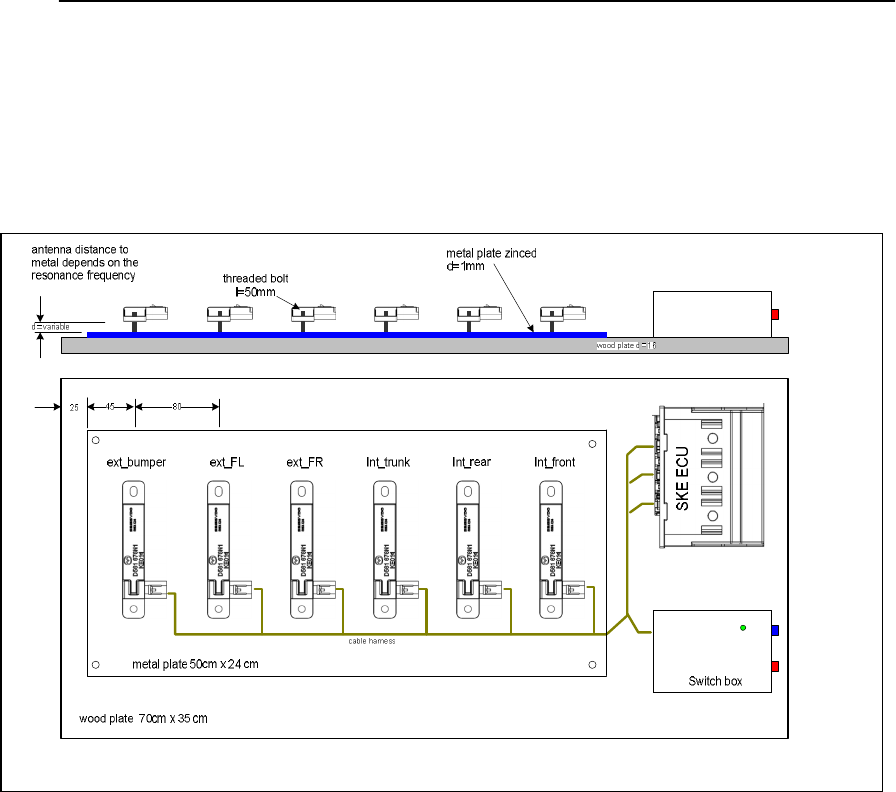
2. FUNCTIONAL DESCRIPTION OF THE MEASUREMENT SYSTEM
The test setup comprises the following components:
- SKE Control unit
- 6 induktive ferrite antennas
- Board for radio homologation measurements (including Wiring harness)
- Key (normal Mode) to verify the function (if attached/required)
- Test box
2.1. FUNCTIONAL DESCRIPTION OF THE MEASUREMENT SYSTEM
The entire setup is supplied with power via the two banana jacks on the test box:
Banana jack, red : +12V DC
Banana jack, black : GND (ground)
The current input (in case of operation) is
min 0,3A/ max 0,8A av. ( min 1,5App/max 8App)
"Main" switch:
"Main" switch on: control unit is powered and the green LED is lighting
"Main" switch off: control module is unpowered
Switches "Ext" and "Int"
"Ext" on, "Int" off: selects functional test and test of emission of external antenna
"Ext" off, "Int" on: selects test of emission of internal antenna
"Ext" off, "Int" off: no mode selected
"Ext" on, "Int" on: no operation is possible when both switches are turned on
2.2. FUNCTIONAL TEST
1. Select "main" switch on

SIEMENS VDO Automotive SV C BC P2 RF
IC:267T-5WK49385 FCC ID:KR5 5WK49385
Page 4 of 4
2. green LED is lighting
3. Turn the switch "ext" on ( make sure switch "int" is off )
4. Place the Id-key (normal Mode) within the marked square on the board. It will
receive the inductive telegram and answer via RF.
5. If an RF telegram from the ID- key is received by the control module, the red
LED is flashing for 200ms.
6. As soon as the ID-Key is brought out of range (use 5m) the red LED will stop
flashing.
2.3. TEST OF EMISSION OF THE EXTERIOR ANTENNA
1. Select "main" switch on
2. Green LED is lighting
3. Turn the switch "ext" on ( make sure switch "int" is off )
4. The control module sends typical every 600ms an inductive telegram via the
exterior antenna
5. Measure the emission
6. After the test switch the switch "ext" and the main switch off.
2.4. TEST OF EMISSION OF THE INTERIOR ANTENNAS
1. Select "main" switch on
2. Green LED is lighting
3. Switch the switch "int" on (make sure switch "ext" is off )
4. The control module sends every 600ms an inductive telegram via the interior
antenna
5. Measure the emission
6. After the test switch the switch "int" and the "main" switch off.