Continental Conair FRS216 FRS+GMRS User Manual FRS316MAN
Continental Conair Limited FRS+GMRS FRS316MAN
User Manual
2
3
1
UHF FM TRANSCEIVER (Family Radio Service)
FRS310HT IB-4833 Printed in China
IMPORTANT SERVICE INFORMATION
SAVE THESE INSTRUCTIONS
BLISTER PACK CONTENTS
Read this manual before attempting to set up or use this instrument.
It contains important information regarding safe installation and use.
Keep this manual for future reference. Also save the carton, packing
and proof of purchase to simplify and accelerate any needed action.
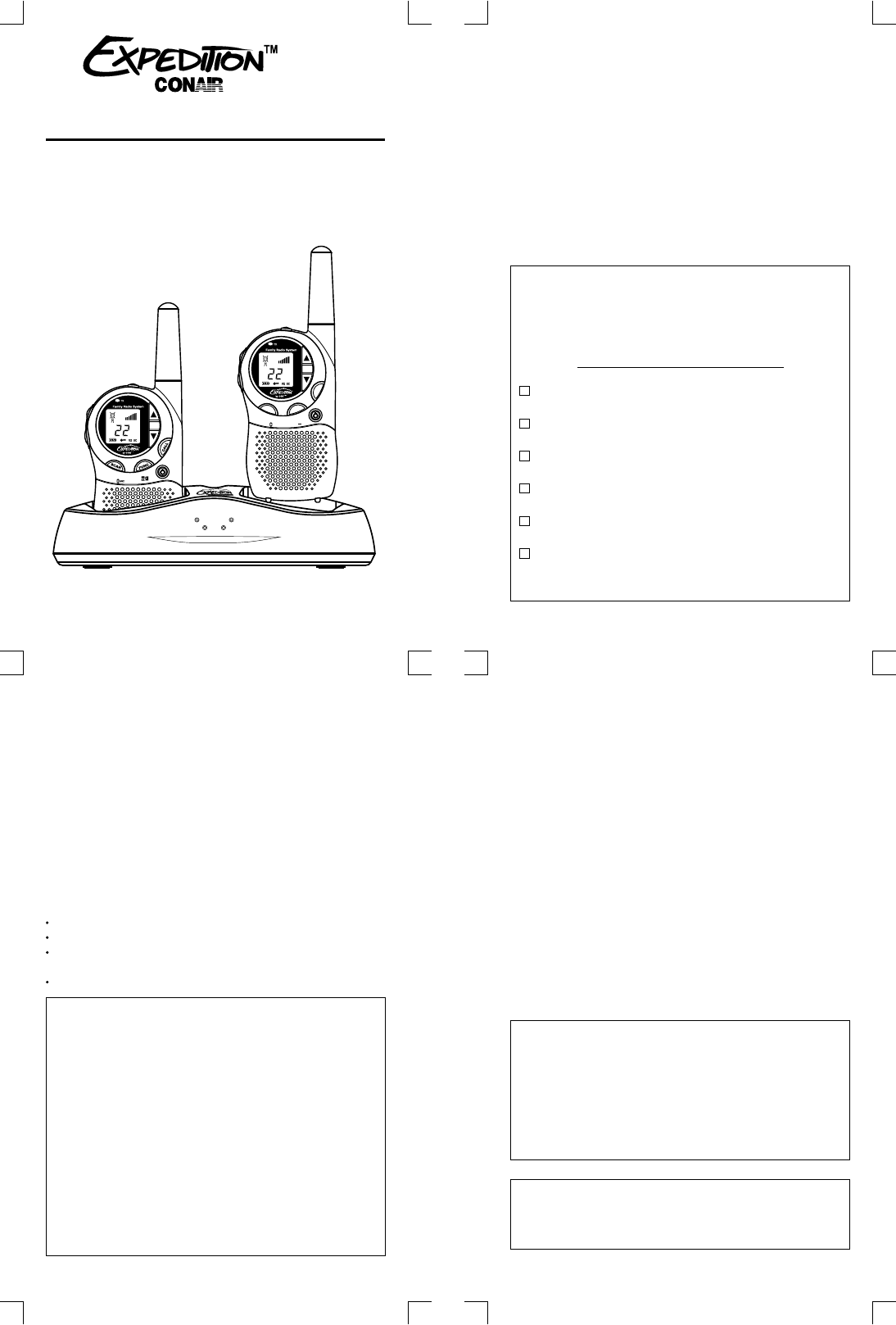
FRS316-Two (2) Two-Way Radios
* Attached to the units at the time of packing
User-Removable Belt Clips*
Two (2) Rechargeable Battery Packs
FRS Charger with AC/DC Adaptor
User's Manual
FCC NOTICE FRS PRODUCT DESCRIPTION
The FCC requires that you be advised of certain requirements involving the use of
this device. This equipment has been tested and found to comply with the limits
for a Class B digital device, pursuant to Part 15 of FCC Rules. These limits are
designed to provide reasonable protection against harmful interference in
residential installation. This device uses and can generate radio frequency energy.
If not installed and used in accordance with the instructions, it may cause harmful
interference to radio communications. However, there is no guarantee that the
interference will not occur in a particular installation. If this equipment does cause
harmful interference to radio or television reception (which can be determined by
turning the unit off and on), the user is encouraged to correct the interference by
one or more of the following measures:
Reorient or relocate the receiving antenna.
Increase the separation between the equipment and receiver.
Connect the equipment to an outlet on a circuit different from that to which the
receiver is connected.
Consult the dealer or an experienced radio/TV technician for help.
FCC WARNING: This equipment generates or uses radio frequency energy.
Adjustment to this unit or replacement of any transmitter component (crystal,
semiconductor, etc.) to this unit that could result in violation of the rules.
FCC INFORMATION: This device complies with part 15 of the FCC Rules.
Operation is subject to the following two conditions:(1) This device may not cause
harmful interference, and (2) this device must accept any interference received,
including interference that may cause undesired operation. Privacy of communications
SAFETY INFORMATION: Your wireless hand-held portable transceiver
contains a low power transmitter. When the PUSH TO TALK (PTT) button is pushed it
sends out radio frequency (RF) signals. The device is authorized to operate at a duty
factor not to exceed 50%. In August 1996, the Federal Communications Commissions
(FCC) adopted RF exposure guidelines with safety levels for hand-held wireless
devices.
may not be ensured when using this equipment.
CAUTION: To maintain compliance with the FCC's RF exposure guidelines hold
the transmitter and ANTENNA at least 1 inch (2.5 cm) from your face and speak
in a normal voice, with the ANTENNA pointed up and away from the face. If you
wear the handset on your body while using the headset accessory, use only the
supplied belt clip for this product and when transmitting, take it out of the belt to
ensure that the ANTENNA is at least 1 inch (2.5 cm) from your body.
Use only the supplied ANTENNA. Unauthorized antennas, modifications, or
attachments could damage the transmitter and may violate FCC regulations.
NOTE: The maximum transmission range will vary depending on terrain and
environment. Range will be greater in open fields, while the range is shorter within
and around buildings or large structures.
FRS316
FRS316
FRS1 FRS 2
BATT 1 BATT 2
by
The FRS316 is compatible with other brands utilizing the same frequency
band (operating in the frequency range from 462.5625MHz to 462.7250MHz).
Please read this user's manual thoroughly to get the most out of your FRS316
two-way radio.
The FRS316 is a 22-channel UHF two-way radio, featuring a multi-functional
LCD panel (which indicates the current channel and various radio status icons).
Other features also include electronic volume control and battery save circuitry.
The FRS/GMRS is the newest generation in personal two-way communications.
The FRS/GMRS operates in a licensed radio band (FCC license is needed for its
operation), on any of the GMRS channels.
The FRS316 is a lightweight, compact two-way radio that can be used up to
about two miles with family or friends at parks, shopping malls, sporting events,
concerts--any indoor or outdoor activity!
SCAN
FUNC
CALL
CH
22
MIC
FCC Licensing Information Insert
SCAN
FUNC
CALL
CH
22
MIC
INSTALLATION
Removing the Belt Clip
Installing the Belt Clip
1.) BELT CLIP LATCH
FIGURE 1
(REAR VIEW)
FIGURE 2
(REAR VIEW)
BELT CLIP SLOT
2.) BELT CLIP
1. Pull the BELT CLIP LATCH (1) away from the unit.
2. While pulling the BELT CLIP LATCH (1), push up on the BELT CLIP (2)
to remove it from the unit, as shown in Figure 1.
1. Slide the BELT CLIP into the BELT CLIP SLOT as shown in Figure 2.
BATT 1BATT 1 BATT 2BATT 2
FRS1FRS1 FRS 2FRS 2
MAXIMUM RANGE PERFORMANCEMAXIMUM RANGE PERFORMANCE
SAFETY INSTRUCTIONS FOR BATTERIES
CONTAINS NICKEL-CADMIUM BATTERY.
BATTERY MUST BE RECYCLED OR
DISPOSED OF PROPERLY.
CAUTION: To reduce the risk of fire or personal injury, read and follow these
instructions.:
1. Use only a CONAIR approved battery pack in FRS316.
a. GP35AAAK4BX 4.8V 350mA GPI International Ltd. or
b. JB35AAANC4BC 4.8V 350mA JB Energy (HK) Ltd.
2. Do not dispose of the battery in a fire, as it may explode. Check with local
codes for possible special disposal instructions.
3. Do not open or mutilate the battery. Released electrolyte is corrosive and
may cause damage to the eyes and skin. It may be toxic if swallowed.
4. Exercise care in handling batteries in order not to short the battery with
conducting materials such as rings, bracelets and keys. The battery or
conduction material may overheat and cause burns.
5. Charge the battery (ies) provided with or identified for use with this product
only in accordance with the instructions and limitations specified in this
manual.
6. Observe proper polarity orientation between the Battery Pack and battery
charger.
natural resources.
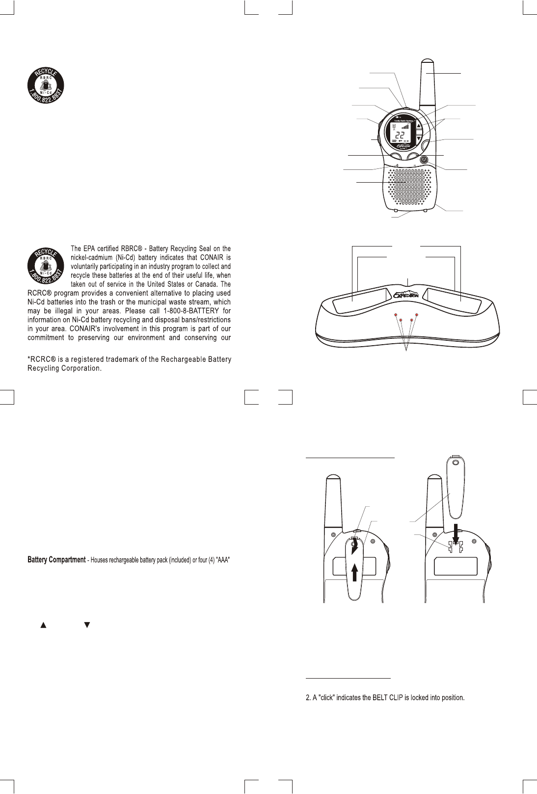
CONTROLS DIAGRAM
CHARGE LED Indicators
BATTERY Cavity
FRS Cavity
POWER-IN CONNECTION Jack
(Located on the rear side)
FRS Cavity - Used to charge the FRS unit. The FRS unit should be in upright position.
BATTERY Cavity - Used to charge the NI-Cd rechargeable battery pack (included).
POWER-IN CONNECTION Jack
CHARGE LED Indicators - Illuminates in red when the Ni-Cd rechargeable battery or
the FRS unit is being charged.
DESKTOP CHARGER
FRS316 UNIT
DESCRIPTION
7
4
5
6
BELT CLIP
(Located on the rear side)
FUNC (FUNCTION)
POWER
PTT (Push
To Talk)
CALL
UP / DOWN
SPEAKER
BATTERY COVER LATCH
(located on the rear side)
MIC
SCAN
MON(MONITOR)
LCD
ANTENNA
BATTERY
COMPARTMENT
(on the rear side)
TX LED
EAR/MIC JACK
Belt Clip - For your convenience, a removable belt clip is included to secure the radio to
a belt, pocket, or any other convenient location.
Power Button - Press and hold the power button to turn your unit ON/OFF.
Transmit (TX) LED - Illuminates in red when transmitting (TX).
PTT (Push To Talk) Button / Switch - Used for transmitting (making a call).
Mon (Monitor) Button - Lets you listen in on a channel for weak signals.
Func (Function) Button - Allows you to change channels. Press and hold for 5 seconds
to LOCK the buttons.
Battery Cover Latch - Secures the battery cover in place.
alkaline batteries (not included).
Scan Button - Used to activate/deactivate the channel scan.
LCD (Liquid Crystal Display) Panel - A multi-functional display which shows channels
and other radio status/icons.
Antenna - This is a fixed antenna.
Call Button - Send call tones for alert or identification purposes.
Up ( ) and Down ( ) Buttons - Used for adjusting the volume level and changing
the channel.
Ear/Mic Jack - This jack is used for optional accessories with Ø2.5mm stereo plug (not
included).
8
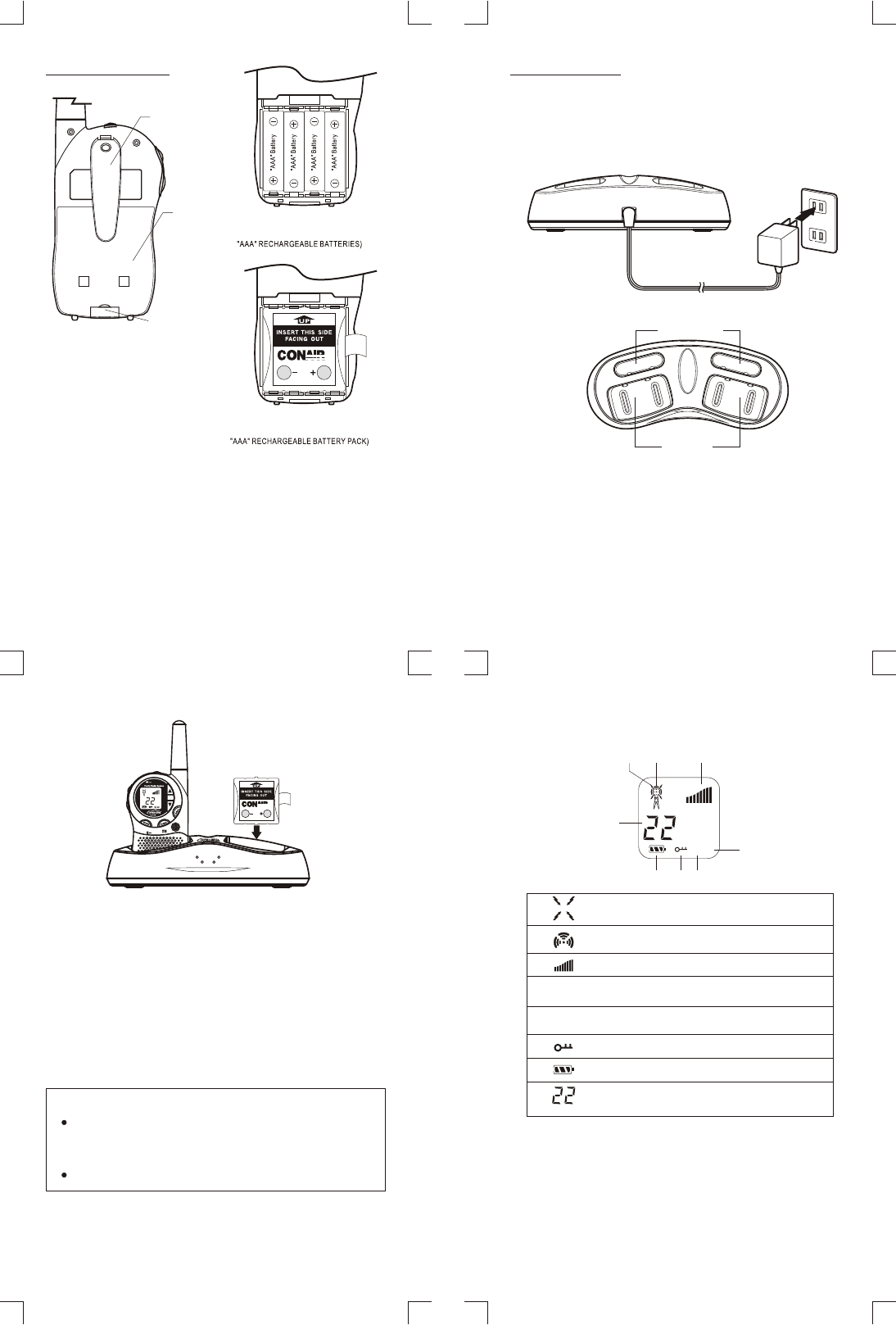
Battery Charging
The battery pack in the unit must be fully charged for 10-14 hours before use.
1. Insert the small plug on the end of the AC adaptor into the POWER-IN
CONNECTION Jack at the back of the desktop charger and plug the AC
adaptor directly into a standard 120V wall outlet.
FIGURE 4
(BATTERY COMPARTMENT WITH
FIGURE 5
(BATTERY COMPARTMENT WITH
1. Release the BATTERY COVER LATCH located on the rear side of the unit.
See Figure 3.
3. Install one (1) four (4) "AAA" alkaline
batteries (not included) following the polarities as shown in Figure 4 and Figure 5.
Ni-Cd rechargeable battery pack (included) or
4. Reinstall the BATTERY COVER and lock the BATTERY COVER LATCH into
position.
2. Remove the BATTERY COVER from the BATTERY COMPARTMENT.
10 1110
The FRS unit has a built-in power saver for maximum battery life. But when
the FRS unit is not being used, conserve battery power by pressing the
Remove the batteries if the unit will not be used for a long period of time.
NOTES:
power button to OFF.
9
®
120V WALL OUTLET
REAR VIEW OF THE CHARGER
TOP VIEW OF THE CHARGER
FRONT VIEW OF THE CHARGER
AC ADAPTOR
2. Place the FRS unit in the charging base upright and facing outward. The
CHARGE LED indicator on the desktop charger will light. If CHARGE LED
indicator is not lit, check position of FRS unit to insure charging contacts
on the unit are lined up with charging contacts on the desktop charger.
3. The CHARGE LED indicator will remain lit while the unit is in the charger.
FRS unit will take approximately 10-14 hours to fully charge before use.
NOTE: 1. If the FRS units or the Ni-Cd rechargeable battery packs are not
placed in the charger correctly, the CHARGE LED indicator will not
NOTE: You can not charge alkaline batteries.
2. Use only the CONAIR AC adaptor and rechargeable battery packs
supplied with this product.
light and the unit will not charge.
BATTERY Cavity
FRS Cavity
Battery Installation
BATTERY COVER
LATCH
FIGURE 3
(REAR VIEW)
BELT CLIP
BATTERY
COVER
LCD PANEL DISPLAY
BC
D
E
F
A
G
H
VX SC
FRS1 FRS 2
BATT 1 BATT 2
UP
INSERT THIS SIDE
FACING OUT
®®
A.
B. - TX icon.
C. -
D.
E.
F. - Displayed when the unit is in
- RX icon. Displayed when receiving a signal.
Displayed when transmitting a signal.
Displays the current VOLUME LEVEL.
SC - Displayed during the CHANNEL SCAN mode.
VX - Displays during the VOX mode.
LOCK mode.
G. - Displays the current BATTERY LEVEL.
H. - CHANNEL NUMBER. Changes from 1 to 22 as selected
by user.
14 15
13
12
panel will display the current channel.
panel will turn blank.
away from the mouth.
Check the channel activity by pressing and holding the MONITOR
button. You'll hear static if the channel is unoccupied. Don't TRANSMIT
if someone is talking on the current channel. Press and hold the PTT
button to TRANSMIT. The TX LED indicator will light up in red. Hold
the unit in a vertical position with the MICROPHONE 2 to 3 inches
1.
2. While holding the PTT button, speak into the unit using a normal tone of voice.
3. Release the PTT button when you have finished transmitting.
NOTE: In order for other people to receive your transmission, they must
also be on the same channel you are currently using. Refer to the
OPERATION
Turning the Unit ON
Turning the Unit OFF
Transmitting a Call
Press the DOWN ( ) button to decrease the .Speaker Volume
Press the UP ( ) button to increase the Speaker Volume.
The level is indicated by the number of bars
displayed in the lower right corner of the LCD panel.
Speaker Volume
Adjusting the Speaker Volume
Receiving a Call
The unit has 22 available channels. To change channels:
1. Press the FUNCTION button the channel number digit flashes on the
LCD panel.
2. While the channel number is flashing:
Press the UP ( ) button to move to a higher channel.
Press the DOWN ( ) button to move to a lower channel.
The channel changes from 1 to 22, or from 22 to 1.
3. Press the FUNCTION button or PTT button to select the desired
channel and return to normal mode.
You can use the MONITOR feature to listen in for weak signals in the
current channel.
Press the MONITOR button for normal monitoring.
monitoring.
CHANNEL SCAN performs searches for active signals in an endless
loop from 1 to 22.
1. Press and release the SCAN button to activate CHANNEL SCAN.
The channel number on the LCD panel changes rapidly until an
active signal is detected.
2. When an active signal (one of 22 channels) is detected, CHANNEL
SCAN pauses keeping the active signal broadcasted.
3. Press the PTT button to communicate through the active signal
channel and CHANNEL SCAN is deactivated.
4. When an active signal (one of 22 channels) is detected, but another
channel is desired, press the SCAN button twice to bypass the
current channel and continue to search for another active channel.
5. Press the SCAN button to deactivate CHANNEL SCAN mode.
Changing Channels
Monitor
Channel Scan
Battery Level / Low Battery Indication
You can use Call Tones to alert the other user or to identify yourself.
You can also use Call Tones to signal the beginning or the end of a
transmission.
1. Press the CALL button, the red TX LED indicator will light up and the
Call Tone continues for 2 seconds.
2. Release the CALL button. Your Call Tones will transmit to a nearby
receivers set to the same channel.
Sending Call Tones
The LCD panel displays the battery power level according to the
number of squares lit inside the battery icon.
When the battery level is low, the battery icon will flash to indicate that
the batteries need to be replaced.
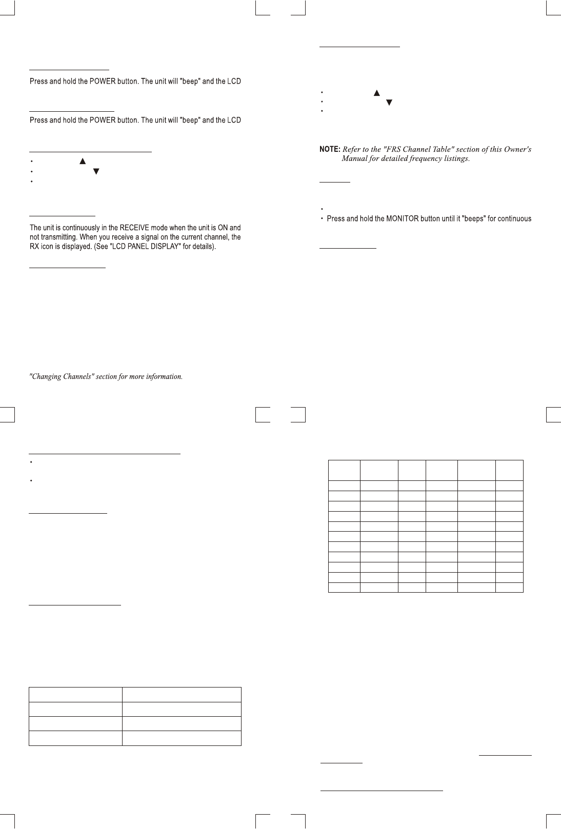
NOTE: Channels 1 to 14 are shared with the FRS radio channels. 15 through 22 are
exclusively for GMRS radios. Operation of this model on GMRS frequencies (Channels
15 thru 22) requires a license from the Federal Communications Commission (FCC).
The maximum transmission range will vary depending on terrain and environment.
462.6250
462.6750
POWER
(Watts)
POWER
(Watts)
FREQUENCY
(MHz)
15
467.6625
467.6875
467.7125
16
17
18
19
20
21
22
CHANNEL
NUMBER
CHANNEL
NUMBER
1
2
3
4
5
6
7
8
9
10
11
12
13
14
0.21
0.09
0.09
0.09
0.21
0.21
0.09
0.21
0.21
0.21
0.21
0.21
0.21
0.21
0.21
0.21
0.21
0.21
0.21
0.09
0.09
0.09
FREQUENCY
(MHz)
467.5625
467.5875
467.6125
467.6375
462.5625
462.5875
462.6125
462.6375
462.6625
462.6875
462.7125
462.5750
462.5500
462.6000
462.6500
462.7000
462.7250
CHANNEL TABLE
FCC LICENSING INFORMATION
Channels 1 thru 7 transmit on FRS/GMRS frequencies.
Channels 8 thru 14 transmit on FRS frequencies.
Channels 15 thru 22 transmit on GMRS frequencies.
Operation on FRS/GMRS and GMRS frequencies require a license
from the Federal Communications Commission (FCC).
Before any station transmit on any channel authorized in the GMRS
from any point within or over the territorial limits of any area where
radio services are regulated by the FCC, the responsible party must
obtain a license for a GMRS system. An individual 18 years of age
or older, who is not a representative of a foreign government, is
Application for a GMRS system license is made on FCC Form 605 and
you can obtain a copy from the FCC's Web site: http://www.fccgov/
formpage.html or by calling the FCC's FormDistribution Center 1-800-
418-FORM(3676), or from the fax-on-demand by dialing (202) 418-0177.
There is a filling fee. For information on fees, see the FCC's Web site:
http://wireless.fcc.gov/csinfo/feeinfo.html.
eligible to apply for a GMRS system license.
You can lock your function keys to ensure your settings will not accident-
ally be changed.
Press and hold the FUNCTION button for 5 seconds until the LOCK icon
symbol is displayed.
Locking Function Keys
22 Channels
0.21W (FCC Maximum)
30 Hours (typical)
About 2 Miles
Channels Available
Output Power (TX)
Range
Battery Life
SPECIFICATIONS
17
SERVICE
LIMITED ONE YEAR WARRANTY
FOR IN-WARRANTY SERVICE
FOR OUT-OF-WARRANTY SERVICE
According to the FCC regulations, this equipment, which has been certified and
registered by the FCC, may only be repaired by authorized persons. If repairs or
adjustments are made by an unauthorized person, the FCC certification may be
voided. Should you encounter any problems, please call the Conair Electronics
Conair, at our option, will replace or exchange (for a model of equal value) your
FRS316 unit for one year from the date of purchase if the unit is defective in
workmanship or materials.
To obtain service under this warranty, return the defective product to the service
center together with your sales slip and $5.00* for postage and handling.
*California residents need only provide proof of purchase and should call 1-800-
366-0937 for shipping instructions.
toll-free Customer Help Line for assistance.
Package your units (include all accessories) and ship the unit postage prepaid*
and insured (for your protection) to:
You may call the Customer Service Help Line for the price of a replacement
before returning the unit. Please follow all instruction for In-Warranty service
(above) to return your unit, and mark the package:
If you have called and know the cost of your replacement, please include this
information with your return for prompt service.
Be sure to include your return address, proof of purchase, a daytime phone
number, $5.00 for postage and handling*, and a brief explanation of the difficulties.
*NOTE: California residents need only provide proof of purchase and should call
1-800-366-0937 for shipping instructions.
Conair Electronics, DEPT. Warranty Repair,
7475 N. Glen Harbor Blvd., Glendale, AZ 85307
DEPT. Out Of Warranty
18
SERVICE CENTER
CONAIR ELECTRONICS
7475 N. Glen Harbor Blvd.
Glendale, AZ 85307
CONAIR ELECTRONICS
Customer Service Help Line:
1-800-366-0937
8:30 a.m. - 9:00 p.m., Monday - Friday
8:30 a.m. - 12:30 p.m., Saturday
www.conairphone.com
Some states do not allow the exclusion or limitation of incidental or consequential
damages, so the above limitation may not apply to you. This warranty gives you
specific legal rights, and you may also have other rights which vary from state to
state.
ALL APPLICABLE IMPLIED WARRANTIES, INCLUDING THE
IMPLIED WARRANTY OF MERCHANDISE AND FITNESS
FOR A PARTICULAR PURPOSE GIVEN TO YOU BY LAW
ARE HEREBY LIMITED IN DURATION OF THIS WARRANTY.
UNDER NO CIRCUMSTANCES WILL CONAIR BE LIABLE
FOR ANY INCIDENTAL OR CONSEQUENTIAL DAMAGES.
16
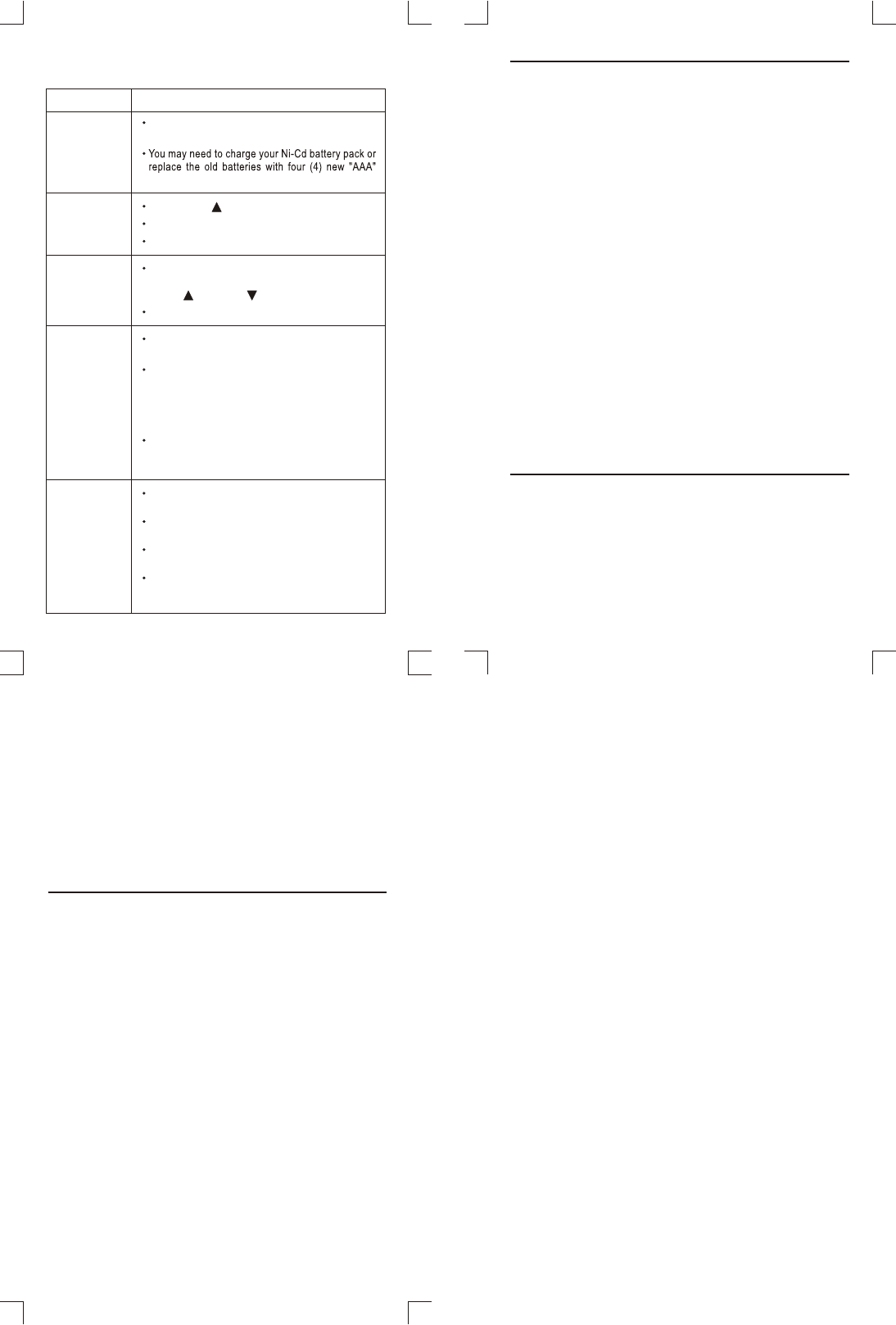
SYMPTOM SOLUTION
No power.
Range is
limited.
The maximum range will vary depending on terrain
and environment. Open fields provide the maximum
range, while steel/concrete structures, heavy foliage
and use in buildings and in vehicles may limit the range
Check batteries. Ensure that the batteries are installed
properly.
Batteries may be weak.
Radios too close. Radios must be at least 5 feet apart;
increase your distance.
If you are receiving, lower the VOLUME to a comfortable
level.
Batteries may be weak. Replace with new batteries if
the BATTERY LEVEL indicator is low.
Sound
distortion
problems.
If you are transmitting, speak in a normal tone of voice
2 to 3 inches away from the MICROPHONE.
Reception
is weak.
Press the UP ( ) button to increase VOLUME.
The receiving signal may be weak and/or out of range.
If this happens, press the MONITOR button.
Cannot
change
channels.
TROUBLESHOOTING
alkaline batteries.
To change channels, press the FUNCTION button until
the channel number flashes on the LCD panel. Press
the UP ( ) or DOWN ( ) buttons to change channels.
significantly.
Wearing the radio close to the body, such as in a
pocket or on a belt, will decrease range; change the
location of the radio.
Radios too far apart. Obstacles interfere with trans-
mission. Talk range is up to 2 miles in clear unobstructed
conditions.