Control Bionics PL-27-1100 The NeuroNode is a Bluetooth Low Energy device allowing alternative computer input. User Manual 27 3500 C
Control Bionics The NeuroNode is a Bluetooth Low Energy device allowing alternative computer input. 27 3500 C
Contents
- 1. Manual
- 2. Operator Manual
Manual

NEURONODE
OPERATOR’S MANUAL
Client Support
USA: (513) 453-4848
AU: (02) 8310-4179
This page is intentionally left blank.

Catalog Number: 27-3500
Revision C
Address comments, questions, or requests pertaining to this manual to:
Control Bionics
745 Center Street, Suite 303
Milford, Ohio 45150
www.controlbionics.com
neuronode@controlbionics.com
04182018
The NeuroNode is listed and registered with the FDA as a Powered Communication System and a Powered Environmental
Control System and certified by the Australian Government Department of Health Therapeutic Goods Administration.
Copyright 2006 - 2017 Control Bionics Inc. All Rights Reserved.
NeuroEDUCATOR® and NeuroNode® are trademarks of Control Bionics Inc.
Apple®, Apple logo®, MacBook®, MacBook Air®, MacBook Pro®, iPad® and iTunes® are
registered trademarks of Apple Inc.
Anatomic images©CLIPAREA l Custom media/Shutterstock.
All other trademarks are the property of their respective owners.
Product design and specifications may be changed without notice.
Patent Pending.
This device complies with part 15 of the FCC Rules. Operation is subject to the following two conditions: (1) This device may
not cause harmful interference, and (2) this device must accept any interference received, including interference that may cause
undesired operation.
NOTE: This equipment has been tested and found to comply with the limits for a Class B digital device, pursuant to part 15 of
the FCC Rules. These limits are designed to provide reasonable protection against harmful interference in a residential installa-
tion. This equipment generates, uses and can radiate radio frequency energy and, if not installed and used in accordance with
the instructions, may cause harmful interference to radio communications. However, there is no guarantee that interference will
not occur in a particular installation. If this equipment does cause harmful interference to radio or television reception, which
can be determined by turning the equipment off and on, the user is encouraged to try to correct the interference by one or
more of the following measures:
• Reorient or relocate the receiving antenna.
• Increase the separation between the equipment and receiver.
• Connect the equipment into an outlet on a circuit different from that to which the receiver is connected.
• Consult the dealer or an experienced radio/TV technician for help.
US: (513) 453-4848
US Toll-free: (855) 831-7521
US Fax: (513) 322-4678
AU: (02) 8310-4179
This page is intentionally left blank.

Contents
1.0 How it Works.................................................................................................
2.0 Overview of Product......................................................................................
2.1 Overview of Accessories.....................................................................
3.0 Accessories....................................................................................................
3.1 Charging the Battery...........................................................................
3.2 Changing the Battery..........................................................................
3.3 Electrode Options..............................................................................
3.4 Leadwire Adapter Base.......................................................................
3.5 NeuroNode Controller Application....................................................
3.5.1 NeuroNode Controller Settings............................................
3.5.2 Graph Settings......................................................................
4.0 Getting Started..............................................................................................
4.1 Electrode Placement...........................................................................
4.2 Connecting the User...........................................................................
4.3 NeuroNode Fundamentals.................................................................
4.3.1 Establishing a Good Signal...................................................
4.3.2 Signal Indicator......................................................................
4.3.3 Battery Management Signal Indicator...................................
4.3.4 Manually Changing the Threshold.........................................
4.4 Turning Switch Control On and Off....................................................
5.0 Accessibility Settings.....................................................................................
5.1 Accessing Accessibility Settings.........................................................
5.2 Switch Control Settings.......................................................................
5.3 Setting an Accessibility Shortcut........................................................
5.4 Setting up Guided Access..................................................................
5.5 Changing From Item Mode to Point Mode........................................
6.0 Troubleshooting.............................................................................................
6.1 NeuroNode Reset and Re-Pair Guide.................................................
6.2 NeuroNode Power Cycle Guide.........................................................
6.3 NeuroNode Battery Changing Guide.................................................
6.4 Pausing a NeuroNode Session...........................................................
6.5 Resuming a NeuroNode Session........................................................
6.6 Pause/Play a NeuroNode Session.......................................................
6.7 Pairing a NeuroNode to a New Device..............................................
2
3
4
5
5
5
6
6
7
9
10
14
14
15
16
16
17
17
18
19
23
23
24
29
30
31
35
35
36
37
38
38
38
39
PAGE 1┃CONTENTS
1.0 How It Works
The NeuroNode uses the body’s bioelectrical EMG (electromyographic) signals to completely
control a computer to generate speech, browse the web, listen to music, and more. It is alterna-
tive/augmentative communication (AAC) technology that is easy to use and works for conditions
like ALS (Lou Gehrig’s Disease), MND, SCI, or cerebral palsy.
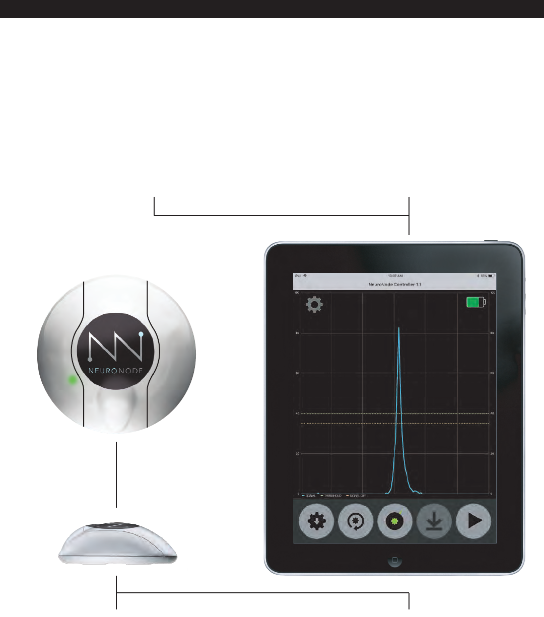
The NeuroNode Controller Application, installed on the
user’s chosen iOS device, is used to set the signaling
threshold while continuously graphing the EMG data
stream. This smart application automatically re-calibrates
to adjust to the user’s strength and energy level without
assistance from a caregiver or clinician.
Clinical-grade EMG electrodes snap to the bottom of the
NeuroNode. The electrodes are non-invasive and simply
adhere to the surface of the skin, anchoring the
NeuroNode directly to the muscle site.
At the core of the NeuroNode System is the NeuroNode,
a wireless, non-invasive EMG switch that communicates
with a computer, tablet, or mobile phone via that device’s
Bluetooth Smart System.
The NeuroNode Assessment System includes an Apple
iPad when requested or required. Apple’s Switch Control
is integrated with the iPad, giving users and therapists
versatile scanning technology to enter text, generate
speech, and more.
PAGE 2┃HOW IT WORKS
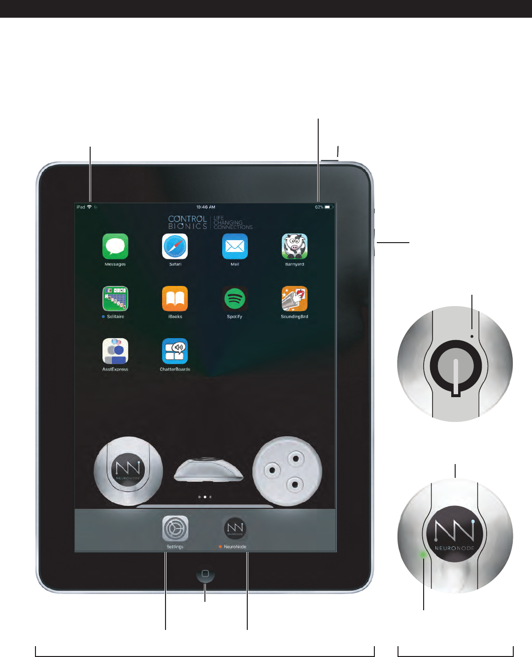
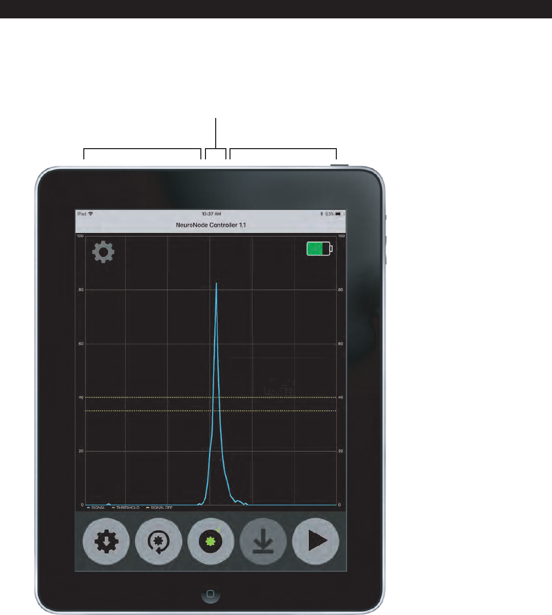
2.0 Overview of Product
iPad WiFi
Connection Status
iPad Battery Level
Indicator
Power
Apple iPad NeuroNode
Signal
Indicator
NeuroNode
Battery Cover
NeuroNode
Threshold Button
Volume
Adjustment
PAGE 3┃OVERVIEW
iPad
Settings NeuroNode
Controller Application
Home
Button
+
+
LIR2032
3.6v
L
I
-
I
O
N
R
E
C
H
A
R
G
E
A
B
L
E
B
A
T
T
E
R
Y
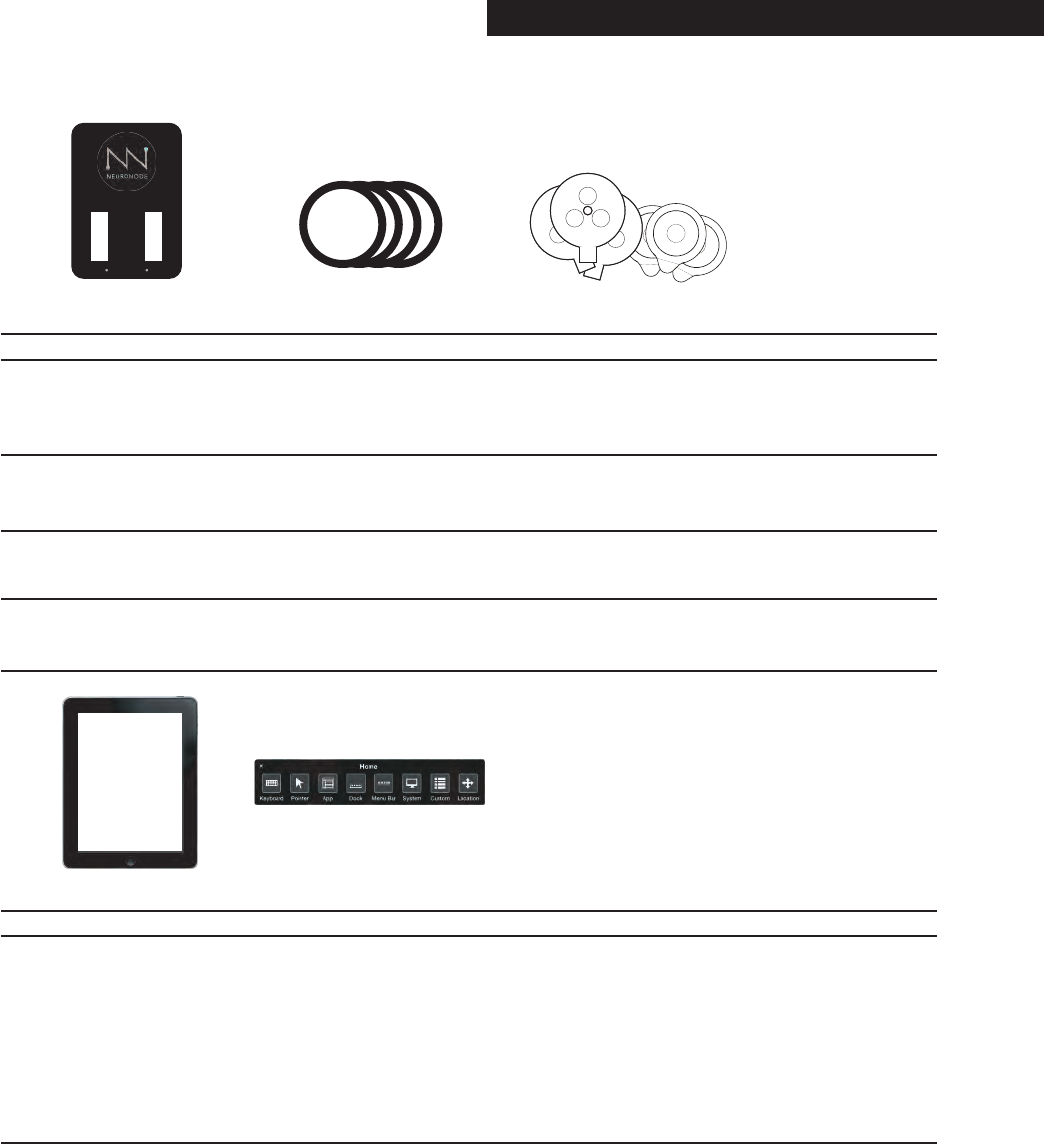
2.1 Overview of Accessories
Leadwire Adapter Base
Electrode KitRechargeable BatteriesBattery Charger
Item What it does
The Leadwires connect to the Leadwire Adapter Base of the NeuroNode. The
three snap-leads on the other end of the Leadwires attach to electrodes on the
user’s skin.
Rechargeable
Lithium-Ion Battery (4)
The NeuroNode comes with 4 rechargeable lithium-ion batteries.
Battery Charger The lithium-ion Battery Charger allows for charging two batteries while using the
previously charged batteries.
Electrode Kit A starter electrode kit is included with the NeuroNode System. Ideally the
optimal electrode type will be determined by the clinician.
Apple iPad
Apple iPad
Apple Switch Control
Item What it does
Item What it does
The NeuroNode gives the user complete control over the device without requiring
extensive computer experience. Here are just a few examples of what persons with
paralysis, loss of speech, or loss of motor control can do with the NeuroNode:
Communicate with family, caregivers, and clinicians using text-to-speech [TTS];
send text messages and email; surf the web; watch videos and movies; listen to
music, radio, and podcasts; read the news; play video games; use environmental
controls; and participate in the classroom using telepresence robots and assistive
technology.
Apple Switch Control The Apple iPad comes with Apple’s Switch Control word prediction and
text-to-speech software. With Switch Control, NeuroNode enables users to
write and have their words spoken by a choice of voices. The prediction accura-
cy will increase as the software learns the words and phrases that are used most
often. Switch Control features include: Self-learning word prediction, history
and sentence prediction, with a choice of an English, Spanish, French, German,
Italian, Swedish, Norwegian, Danish or Dutch user interface.
+
LIR2032
3.6v
L
I
-
I
O
N
R
E
C
H
A
R
G
E
A
B
L
E
B
A
T
T
E
R
Y
+
LIR2032
3.6v
L
I
-
I
O
N
R
E
C
H
A
R
G
E
A
B
L
E
B
A
T
T
E
R
Y
+
LIR2032
3.6v
L
I
-
I
O
N
R
E
C
H
A
R
G
E
A
B
L
E
B
A
T
T
E
R
Y
+
LIR2032
3.6v
L
I
-
I
O
N
R
E
C
H
A
R
G
E
A
B
L
E
B
A
T
T
E
R
Y
- +
- +
PAGE 4┃OVERVIEW
3.0 Accessories 3.1 Charging the Battery
3.2 Changing the Battery
- +
- +
Using the provided cable, connect the charger to the
provided wall port.
Carefully insert the rechargeable Lithium-Ion batteries
into the charger. Be sure to align the positive sides of
the batteries with the “+” labels on the charger.
Two batteries must be inserted into the charger in order
to charge.
A red light indicates charging, a green light indicates
charged.
NEG
+
+
+
LIR2032
3.6v
L
I
-
I
O
N
R
E
C
H
A
R
G
E
A
B
L
E
B
A
T
T
E
R
Y
A. Carefully remove the battery cover on the
NeuroNode.
B. If replacing the battery, gently lift the discharged
battery upward and slide it out from beneath the
“+” terminal spring.
C. Place the fully charged, rechargeable lithium-ion
battery beneath the “+” terminal spring, with the
positive side facing up.
D. The initiating lighting sequence should begin,
indicating a powered NeuroNode. Carefully
replace the battery cover on the NeuroNode to
start or continue the session.
PAGE 5┃ACCESSORIES
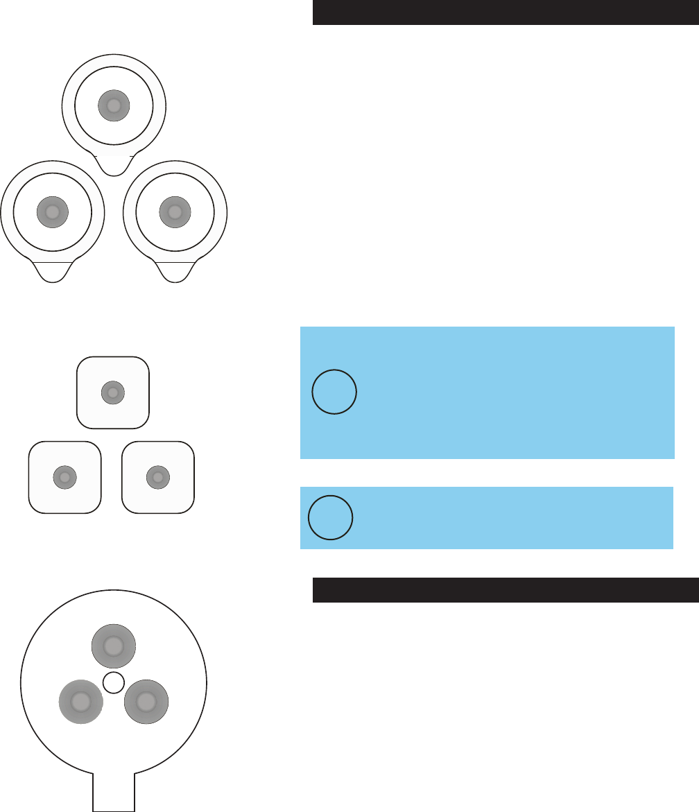
3.3 Electrode Options
In order to use Leadwires for individual electrodes, the
NeuroNode comes with a Leadwire Adapter Base.
Simply orient the plastic keying points on the face of the
adapter plate with the matching keying points on the
bottom of the NeuroNode.
Take care that the two pieces are aligned before snap-
ping them together.
Observe the black and white color coding of the Lead-
wires (two white, one black) and match them to the
accompanying connectors exiting the
Adapter Plate.
3.4 Leadwire Adapter Base
Good skin prep and proper electrode arrangement are
all-important. EMG signals measure in the millionths of
a volt, and extraneous electrical signals are every-
where—from cell phones to transmission towers to
fluorescent lights. Proper electrode set-up helps to
ensure that the NeuroNode circuitry can tease out these
unwanted signals, leaving only the EMG signal to be
processed as the "switch" for the NeuroNode
Application.
Use a skin prep to remove oils, dirt, and dead skin cells
from the surface of the skin. At the very least, slightly
abrade the Target Muscle Site with a dry towel or a
washcloth. This will help to ensure good contact is
made between the skin and the conducting surface of
the electrodes.
THE SINGLE ADHESIVE DISK WITH 3 SNAP
CONNECTORS IS THE MOST CONVENIENT
ELECTRODE INTERFACE; HOWEVER, SOME
USERS WILL NEED TO USE INDIVIDUAL GELLED
ELECTRODES TO PRODUCE A RELIABLE EMG
SIGNAL.
PLEASE CONTACT CONTROL BIONICS FOR
ELECTRODE PART NUMBERS AND
PRICING.
!
Single Adhesive Disk with 3 Snap Connectors
(non-gelled)
Individually Gelled Electrodes
(size will vary)
Individually Gelled Electrodes
(size will vary)
PAGE 6┃ACCESSORIES
!
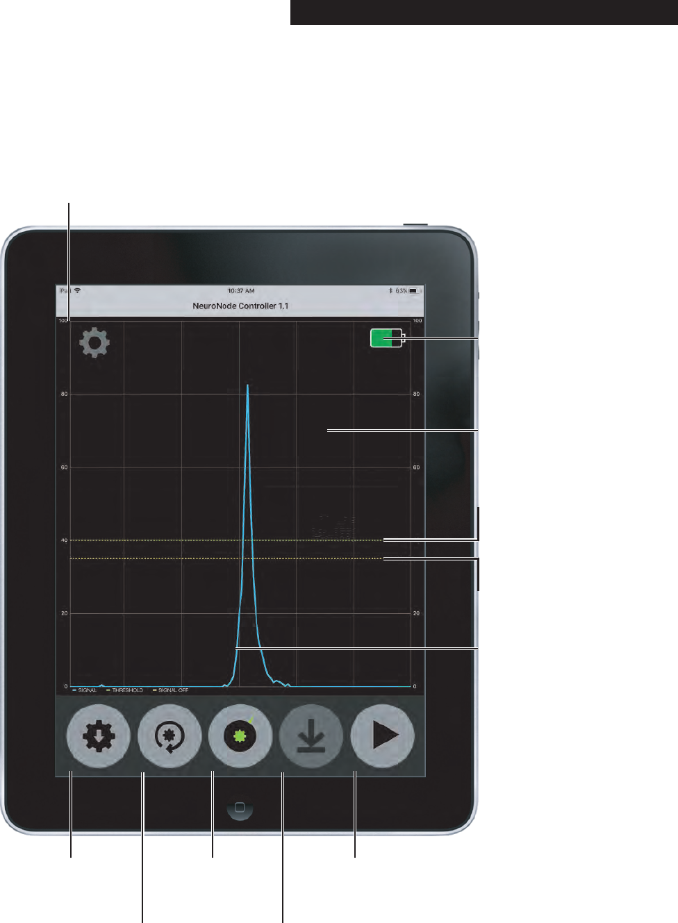
3.5 NeuroNode Controller Application
The NeuroNode EMG Augmented Assistive Communi-
cations (AAC) Controller Application is designed to pair
with the Control Bionics NeuroNode assistive control
device. The application allows the user to adjust param-
eters and monitor EMG signal activity to ensure optimal
signal outcomes that provide efficient and effective
control of an iOS device utilizing Apple’s
Accessibility Suite.
NeuroNode Battery
Level Indicator
Grid Lines
NeuroNode Controller
Settings
Save
Settings
Restore
Settings Reset
Resting
Level
Edit Graph
Settings Pause/Play
EMG
Signal
Threshold Level
Indicator
Signal Off
Level Indicator
PAGE 7┃ACCESSORIES
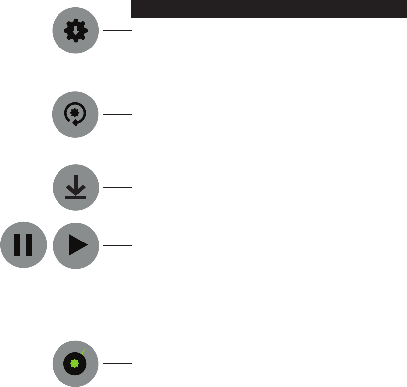
3.5 NeuroNode Controller Application
Save Settings:
Touching this button will direct the NeuroNode to store
the current Switching parameters (see Display Settings)
once the devices Bluetooth is turned off. On power-up,
the NeuroNode will load these saved settings to be
used as the working Switching parameters.
Restore Settings:
Touching this button will set the Application and the
NeuroNode working Switching parameters to the
parameters read from the NeuroNode when the Appli-
cation was initially launched.
Reset Resting Level:
Touching this button will set a new baseline based on
the user's current EMG resting level. The button is
grayed-out if Auto Baseline is not turned on.
Pause/Play:
Touching this button will toggle the real-time EMG
graph on (sweeping) and off (paused). Pausing the
graph will put the NeuroNode in a low-power mode,
nearly tripling its battery life. Also, when Paused, the
NeuroNode will be disconnected as an input device.
This can be helpful for performing maintenance or
updates to the iPad that require the touchpad.
Graph Settings:
Refer to Section 3.5.2 to learn more about the
NeuroNode Controller Graph Settings.
PAGE 8┃ACCESSORIES
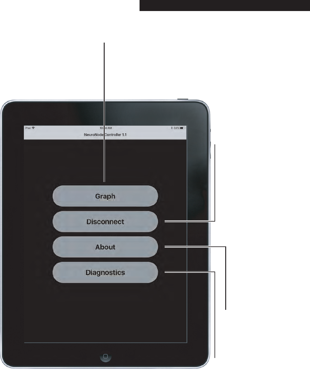
3.5.1 NeuroNode Controller Settings
PAGE 9┃ACCESSORIES
View Graph
Disconnect:
Touch on this button at times
when the battery needs
changed or when the
NeuroNode will be out of use
for more than 60 minutes. For
shorter breaks in a session (and
to conserve battery life),
consider using the Pause
button on the Graph Display to
put the NeuroNode to sleep.
Diagnostics:
Presently this is for use only by
Control Bionics personnel.
About NeuroNode:
Touch here to display
identifying information about
this NeuroNode system,
including the serial number of
the NeuroNode, the software
version of the Application, and
the software version of the
NeuroNode itself.

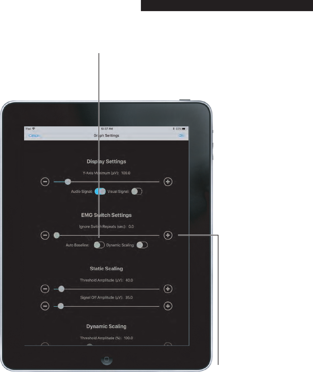
3.5.2 Graph Settings
Access the Graph Settings by selecting the Graph
Settings icon in the center of the Applications Icon
dock.
Continue in this section to understand the various
Graph Settings options.
PAGE 10┃ACCESSORIES
Visual Signal Indicator:
Directs the Application to flash
the display when a Switch is
made (i.e., when the signal
crosses above the Threshold
Amplitude).
Y-Axis Maximum:
Sets the full-scale range of the graph. Setting
this parameter to 100 microvolts, for
example, will allow EMG signals of 0 to 100
microvolts to fully appear on the graph.
Audio Signal Indicator:
Directs the Application to
beep when a Switch is
made (i.e., when the signal
crosses above the
Threshold Amplitude).
3.5.2 Graph Settings
PAGE 11┃ACCESSORIES
Auto Baseline Indicator:
Sets the NeuroNode to a mode of
operation where it will set a new
baseline based on the user's current
resting level. If the resting level
decreases, the NeuroNode will use
the new resting level as the baseline.
Ignore Switch Repeats:
This setting is helpful when
the user is getting "false"
Switches after the original
Switch. These unintended
Switches can be the result of
fasciculation or an inability to
relax after making the original
Switch. Most Assistive Tech-
nology software suites have a
similar setting, but the imple-
mentation details can vary. As
offered by the NeuroNode
Application, saving the Ignore
Switch Repeats setting to the
NeuroNode can provide more
consistent Switching perfor-
mance across multiple
platforms and applications.

Static Scaling imposes fixed criteria that the EMG signal
must satisfy in order to be counted as a Switch. These
criteria remain unchanged over time.
Signal Off Amplitude:
Sets the EMG amplitude a
signal counted as a Switch
must fall below before a new
Switch can be counted.
Setting this parameter at the
same level as the Threshold
Amplitude will remove Signal
Off Amplitude as a Switching
determiner.
Threshold Amplitude:
Sets the EMG amplitude the
signal must cross above in
order to be counted as a
Switch.
3.5.2 Graph Settings
PAGE 12┃ACCESSORIES
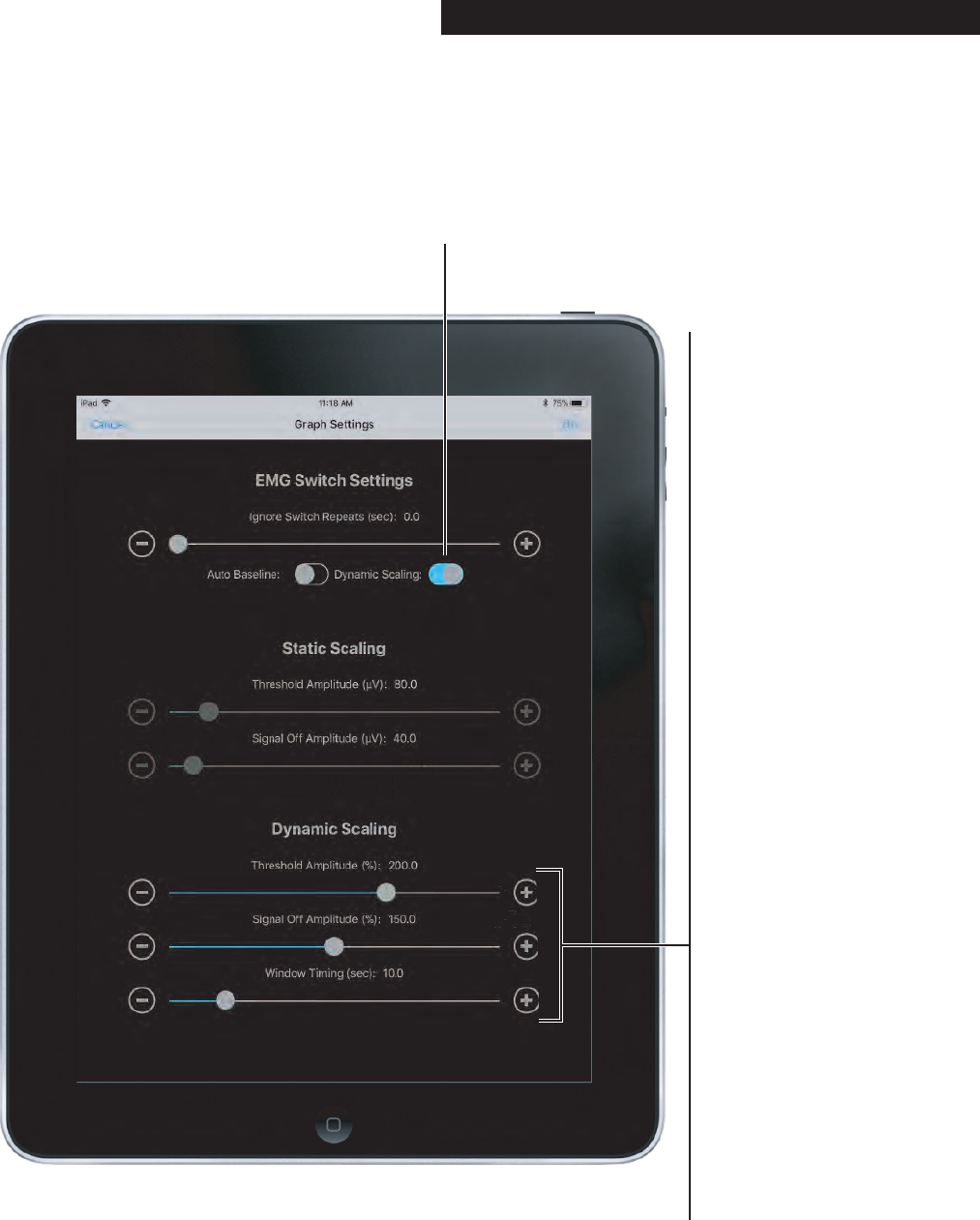
Dynamic Scaling changes the criteria over time for
determining if a Switch has been made based on the
user's performance. The EMG resting level and the
EMG signaling level are both used in this ongoing
calculation. As such, the NeuroNode will make it easier
to Switch as the user fatigues, or as the electrode
interface conditions change.
3.5.2 Graph Settings
PAGE 13┃ACCESSORIES
Threshold Amplitude:
Sets a scale for use when
in the NeuroNode’s
Dynamic Scaling Mode.
The lower the level, the
more sensitive the
NeuroNode will be in
allowing a Switch to be
made.
Signal Off Amplitude:
Sets the level a Switch
signal must drop below
before another Switch is
allowed. Setting this at
100% will set the Signal
Off Amplitude to the user’s
ongoing average Resting
Level. Setting this parameter
at the same level as the
Threshold Amplitude will
remove Signal Off
Amplitude as a Switching
determiner.
Window Timing:
The Dynamic Scaling
Window slider sets the
amount of signaling activity
the NeuroNode will exam-
ine in order to adjust the
levels for Threshold Ampli-
tude and Signal Off. A
shorter window duration will
make the NeuroNode
respond faster to changes in
EMG signaling and resting
levels. A longer duration will
allow the NeuroNode to
respond more accurately to
long-term trends in the
EMG levels.
Dynamic Scaling Indicator:
Sets the NeuroNode to the
Dynamic Scaling Mode.
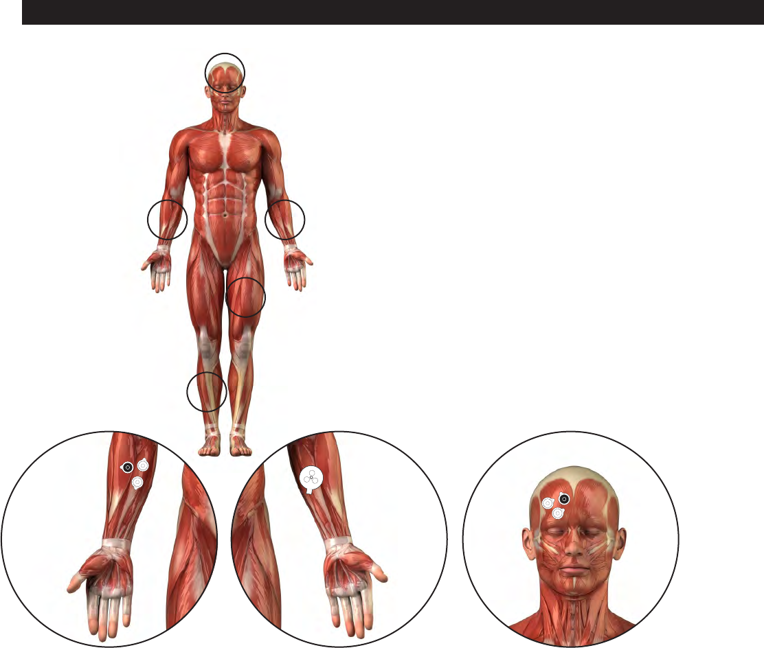
4.0 Getting Started 4.1 Electrode Placement
The EMG Target Muscle is chosen during the assess-
ment but can be changed at any point. Only one
effective Target Muscle is needed to use the
NeuroNode. This muscle is chosen based on two
criteria: it should respond, at least minimally, to a
command to contract it; and it should return to a resting
state in a timely manner.
The muscle does not need to function at optimal levels.
The NeuroNode is designed to respond reliably and
accurately to minimal signals at the Target Muscle site.
PAGE 14┃GETTING STARTED
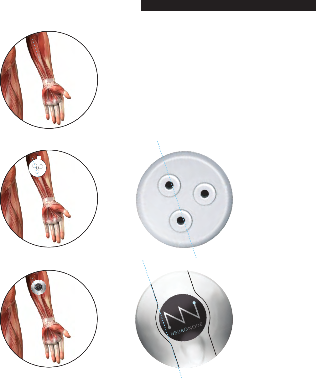
4.2 Connecting the User
Although the placement of the NeuroNode does not
have to be exact, there are some general guidelines for
placing the device onto the muscle site.
When using a “Triple” electrode, the two active
electrodes are located on the bottom of the
NeuroNode, running parallel to the battery cover.
When using “Single” electrodes and the Leadwire
Adapter Base, the two active electrodes (white snaps)
should be placed along the length of the muscle which
is being used to generate a “Switch.” The reference
electrode (black snap) should be placed, forming a
triangle, to one side or another of the two active
electrodes.
PAGE 15┃GETTING STARTED
Before starting Switch Control, it is important to estab-
lish a good signal with the NeuroNode. This will
become the user’s “Switch” for selecting items on the
iPad.
Most importantly, there should be a clear delineation
between the “resting” level and the “switching” level.
PAGE 16┃GETTING STARTED
4.3. NeuroNode Fundamentals 4.3.1 Establishing a Good Signal
Resting Level Resting Level
Switching
Level
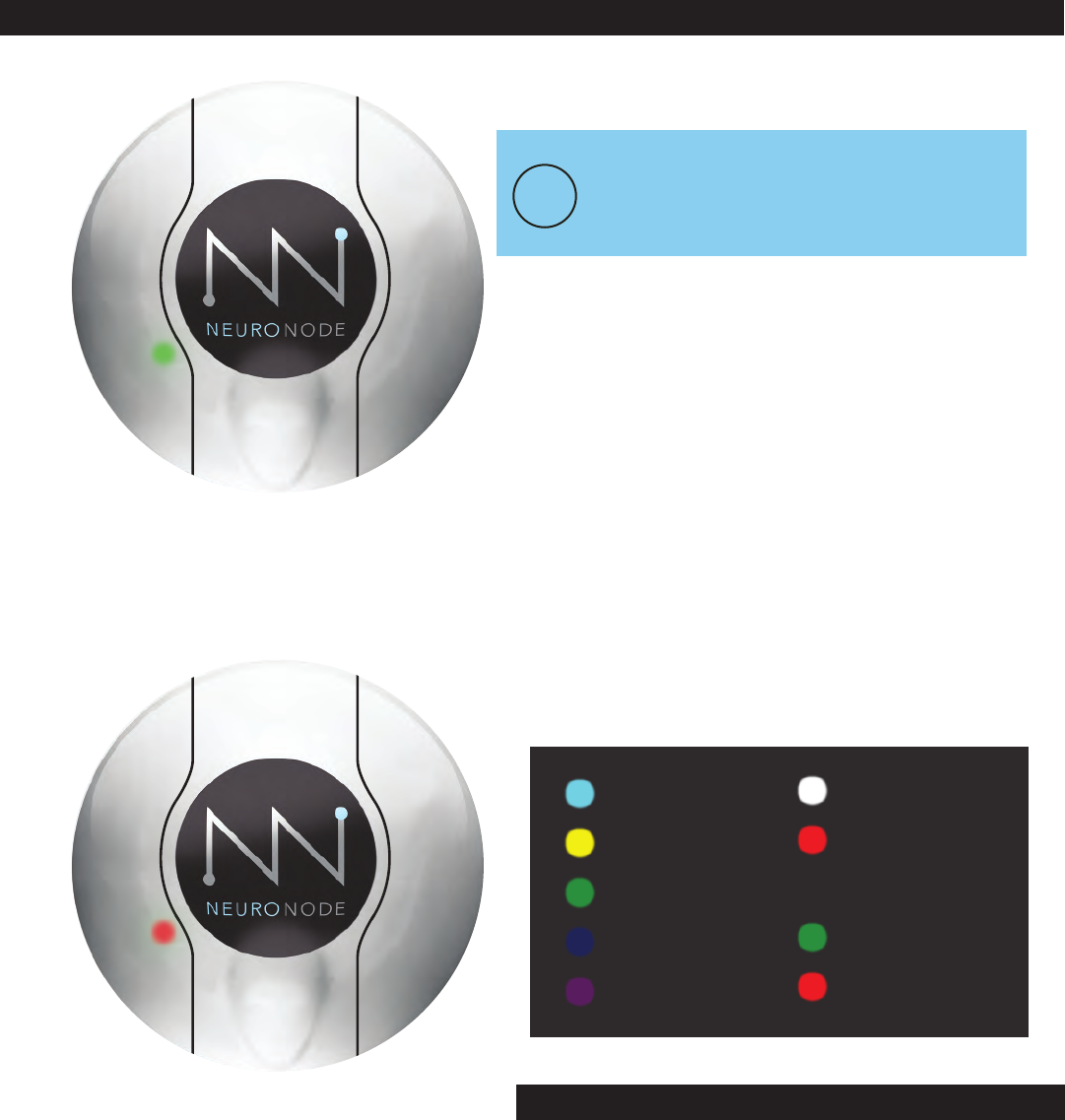
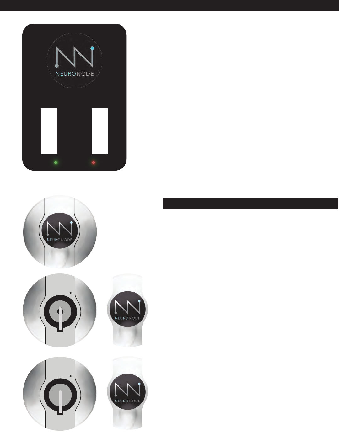
The NeuroNode is built to be a stand-alone EMG
switch, capable of pairing with a variety of devices.
As a stand-alone switch, the NeuroNode has built-in
indicators in order to visually cue the user at the
instance of a good signal or switch.
A green light indicates an EMG signal was counted as a
switch.
A blinking red light indicates the NeuroNode is
Bluetooth broadcasting.
Upon powering the NeuroNode, the device will go
through a launch sequence as a series of colors: red,
green, blue, and white.
After passing through this launch sequence, the
NeuroNode will remain on a solid color for a few
seconds. This color indicates the set Threshold level.
See the guide below to determine the signal level that
correlates to the indicated color.
US: (513) 453-4848
US Toll-free: (855) 831-7521
US Fax: (513) 322-4678
AU: (02) 8310-4179
US: (513) 453-4848
US Toll-free: (855) 831-7521
US Fax: (513) 322-4678
AU: (02) 8310-4179
US: (513) 453-4848
US Toll-free: (855) 831-7521
US Fax: (513) 322-4678
AU: (02) 8310-4179
Dynamic Scaling
Bluetooth
Broadcasting
Custom Static
Scaling
200 Microvolts
100 Microvolts
50 Microvolts
20 Microvolts
10 Microvolts
EMG Signal Made
IF USING THE NEURONODE WITH AN iOS
DEVICE, IT IS BEST TO SET THE SENSITIVITY
WITHIN THE NEURONODE CONTROLLER
APPLICATION.
!
PAGE 17┃GETTING STARTED
4.3. NeuroNode Fundamentals 4.3.2 Signal Indicator
The NeuroNode Signal Indicator light will start blinking
yellow when the battery voltage drops below 3.5 Volts,
indicating that they battery should be replaced within
10-15 minutes. The NeuroNode will remain usable and
continue blinking yellow until the battery voltage falls to
3.4 Volts.
When the NeuroNode battery voltage drops below 3.4
Volts, the Signal Indictor light will remain solid yellow
and the device will no longer be usable.
4.3.3 Battery Management Signal Indicator
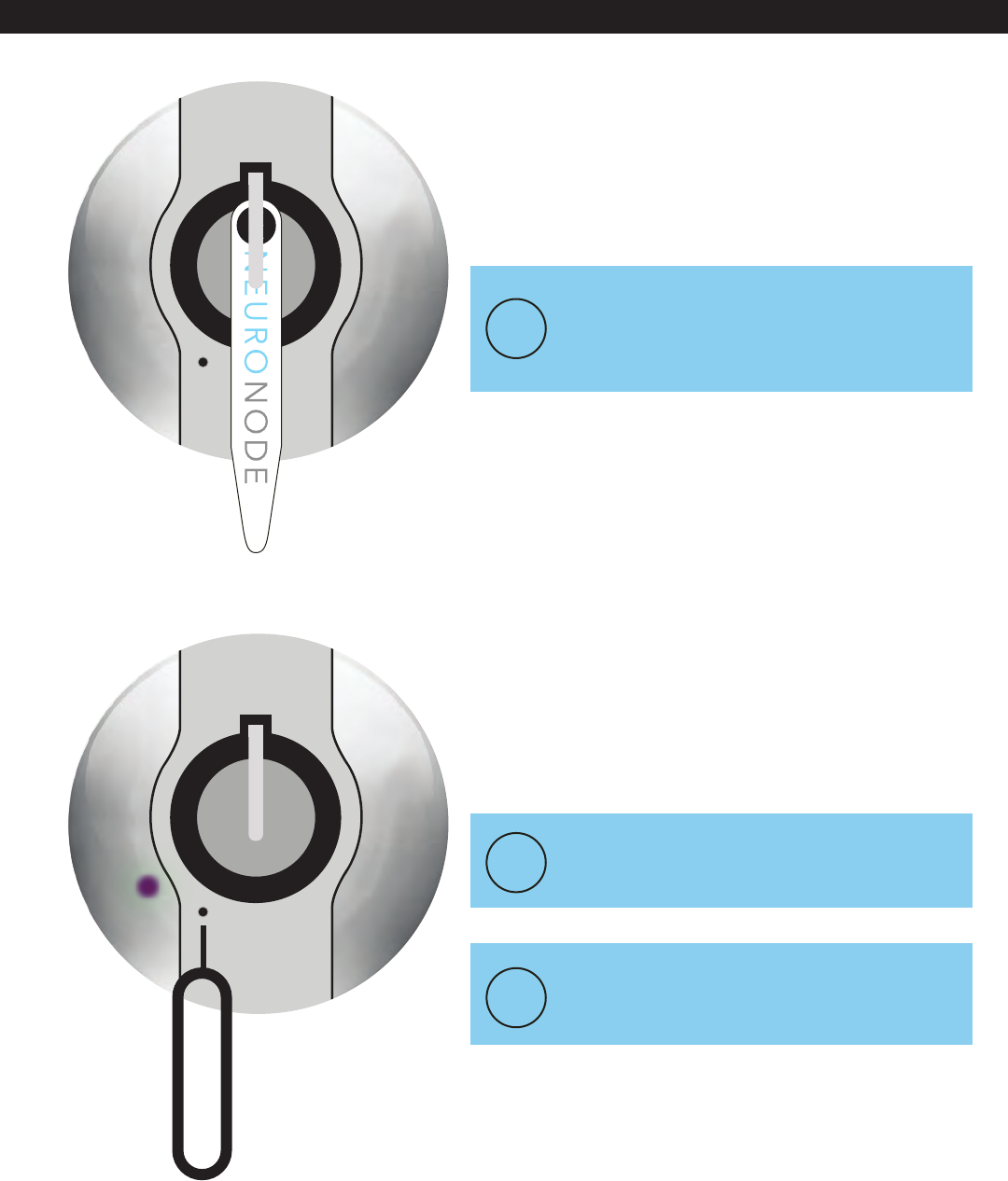
In order to manually set the user’s Threshold, follow
these steps:
1. Ensure the device Bluetooth is “OFF.”
2. Power on the NeuroNode by inserting the battery or
performing a power cycle with the provided collar
stay.
3. Upon performing a power cycle on the NeuroNode,
the device will go through a launch sequence as a series
of colors: green, blue, red and white. After passing
through this launch sequence, the NeuroNode will
remain on a solid color for a few seconds. This color
indicates the set Threshold level. use the provided
push-pin tool to cycle through the threshold colors
(indicated in section 4.3.2) until the desired sensitivity is
reached.
4. Attach the NeuroNode to the electrodes.
5. Attach the electrodes to the user’s skin.
6. Test the user’s signaling ability using the signal
indicator light.
7. Turn on the device Bluetooth.
IF THE SIGNAL INDICATOR IS ALWAYS
GREEN, SET THE THRESHOLD TO A HIGHER
SCALE.
!
TO INITIATE A POWER CYCLE, INSERT AND
THEN REMOVE THE COLLAR STAY, OR SHIM,
FROM IN BETWEEN THE BATTERY TOP AND
THE "+" TERMINAL SPRING.
!
!IF THE SIGNAL INDICATOR NEVER TURNS
GREEN, SET THE THRESHOLD TO A LOWER
SCALE.
+
+
LIR2032
3.6v
L
I
-
I
O
N
R
E
C
H
A
R
G
E
A
B
L
E
B
A
T
T
E
R
Y
+
+
LIR2032
3.6v
L
I
-
I
O
N
R
E
C
H
A
R
G
E
A
B
L
E
B
A
T
T
E
R
Y
PAGE 18┃GETTING STARTED
4.3. NeuroNode Fundamentals 4.3.4 Manually Changing the Threshold
4.4 Turning Switch Control On and Off
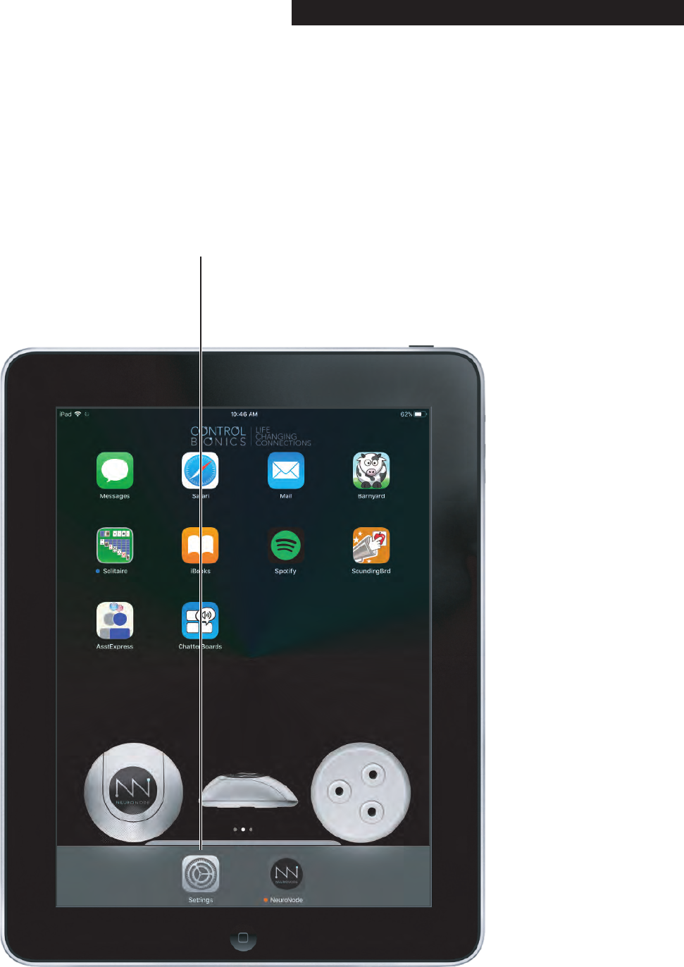
Turn Switch Control on and off following the steps in this
section.
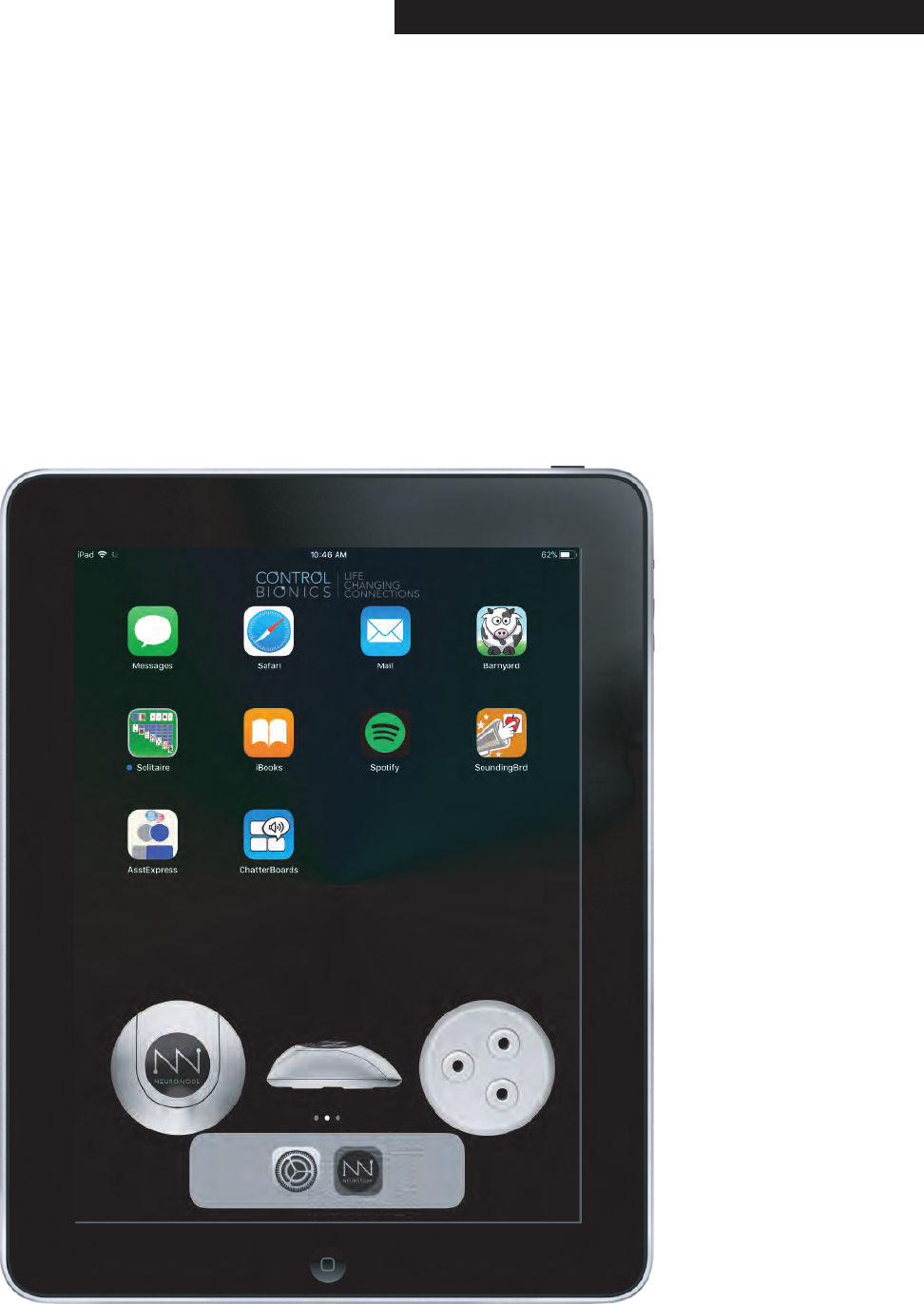
Step 1:
Select the Settings icon
on the iPad.
PAGE 19┃GETTING STARTED
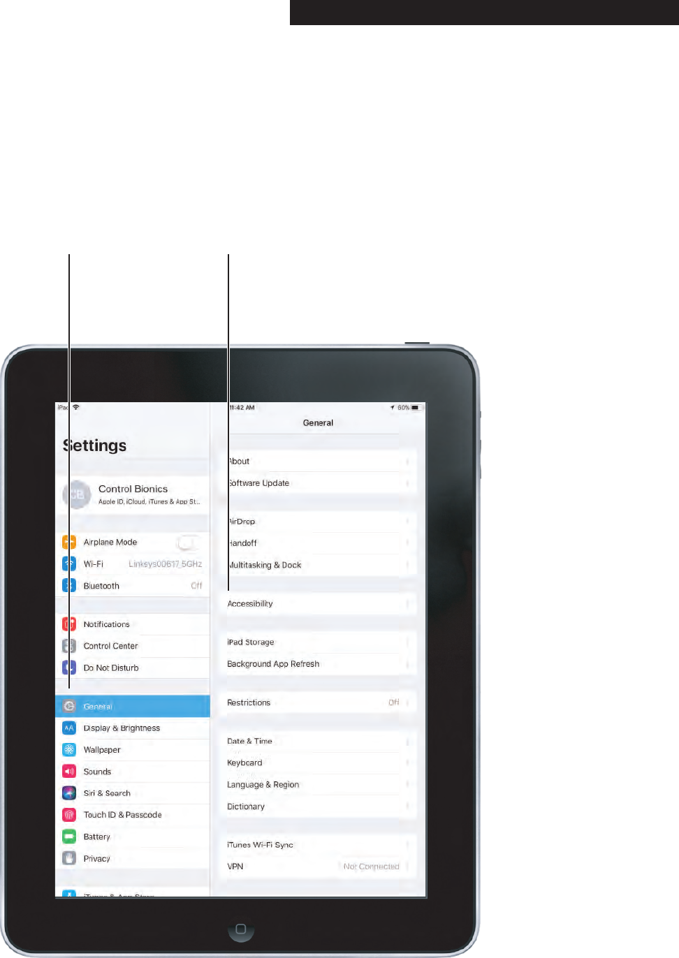
4.4 Turning Switch Control On and Off
Step 2:
Select the General
tab within Settings
Step 3:
Select the Accessibility
Settings within the
General tab
PAGE 20┃GETTING STARTED

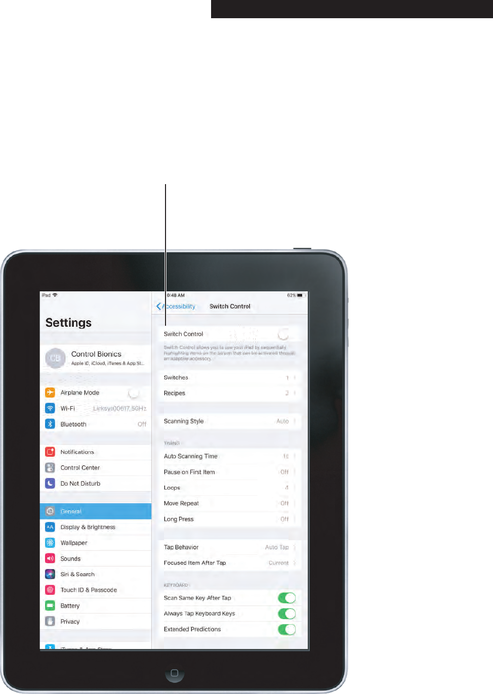
4.4 Turning Switch Control On and Off
Step 4:
Select Switch Control
within the Accessibility
tab
PAGE 21┃GETTING STARTED
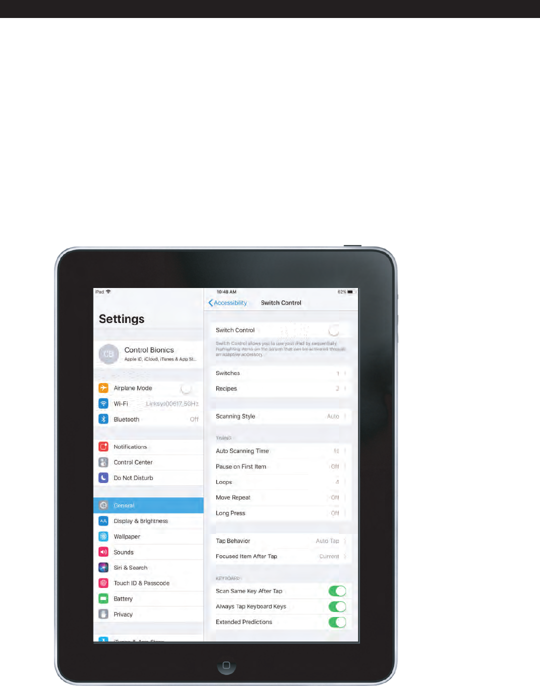
4.4 Turning Switch Control On and Off
Step 5:
Tap on the Switch
Control switch to turn
on Switch Control
A green Switch Control switch indicates Switch Control
is on. A gray Switch Control switch indicates that Switch
Control is off.
If the iPad was provided by Control Bionics, pressing
the iPad’s Home Button three times in quick succession
will turn Switch Control on and off.
PAGE 22┃GETTING STARTED
5.0 Accessibility Settings 5.1 Accessing Accessibility Settings
To access Apple’s Switch Control and Accessibility
settings, follow steps 1-4 outlined in section 4.4.
Continue in this section to understand the various
settings listed within this Accessibility Menu.
PAGE 23┃ACCESSIBILITY SETTINGS
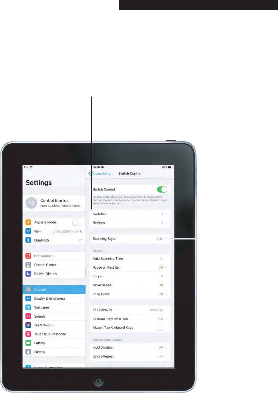
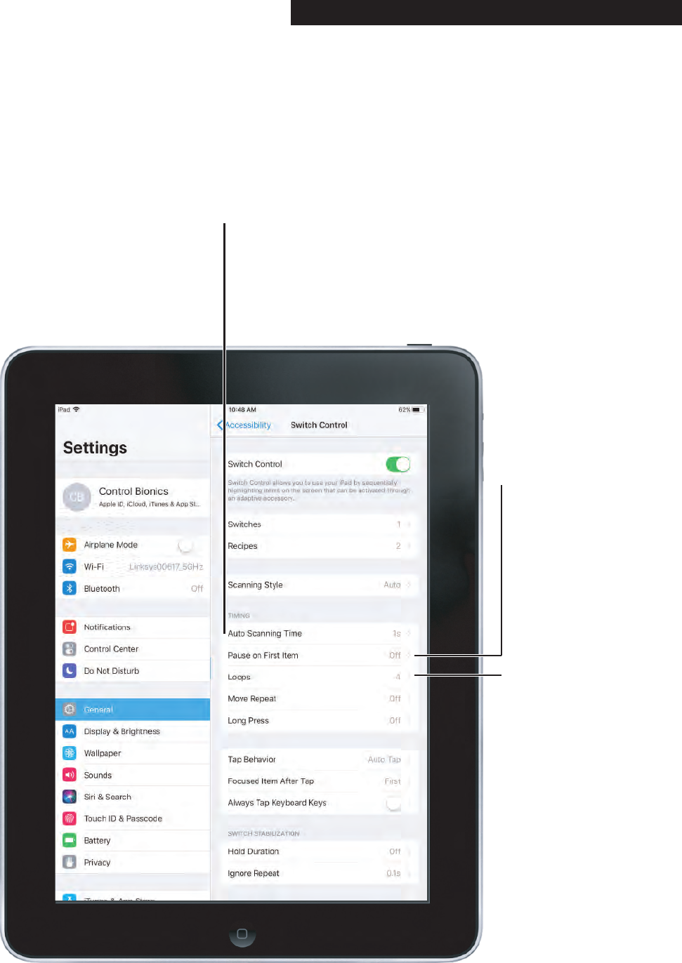
5.2 Switch Control Settings
Switches:
Switch Control can be
configured with multiple
switches. For the NeuroNode
the Switch Action should be
Select Item.
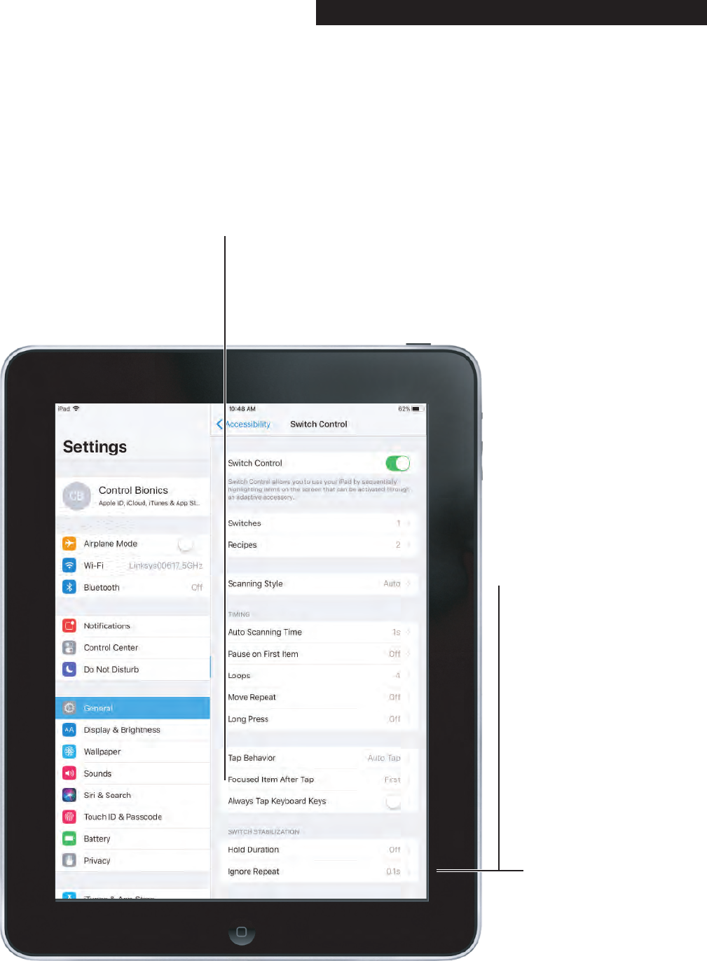
Scanning Style:
Auto Scanning - this selection
moves the focus while
scanning after a set duration.
Manual Scanning - this
selection requires a switch
to be made in order to move
focus, and another switch to
be made in order to select an
item.
Single Switch Scanning - this
selection requires a switch to
be made in order to move
focus. If no action is taken
after a set duration, the item
with focus is automatically
selected.
For the NeuroNode the
Scanning Style should be
“Auto Scanning.”
PAGE 24┃ACCESSIBILITY SETTINGS
5.2 Switch Control Settings
Auto Scanning Time:
The number of seconds, up to
25, it takes to step from one
item to another in a panel when
using Auto Scanning Style.
Loops:
This sets the number of
times Switch Control
repeats a scan.
Pause on First Item:
The number of seconds,
up to 8, that auto scanning
stays on the first item in a
panel, group, or user
interface.
PAGE 25┃ACCESSIBILITY SETTINGS

5.2 Switch Control Settings
Tap Behavior:
This setting adjusts what
happens when a switch
is activated to select an item.
Default - the default setting
will show the Scanner Menu
upon selecting an item.
Auto Tap - this setting will
automatically select the item
unless another switch is
made during the set duration,
at which time the Scanner
Menu will appear.
Always Tap - this setting will
automatically select the
highlighted item instead of
showing the Scanner Menu.
This setting only works while
scanning in Item Mode and
puts the Scanner Menu at
the end of the scan.
PAGE 26┃ACCESSIBILITY SETTINGS
5.2 Switch Control Settings
Focused Item After Tap:
This setting determines where
the scan restarts after an item is
selected, either the “First Item”
(i.e., the beginning of the scan)
or at the “Current Item.”
Ignore Repeat:
The number of seconds,
up to 10, during which
repeated pressing of a
switch is ignored.
PAGE 27┃ACCESSIBILITY SETTINGS
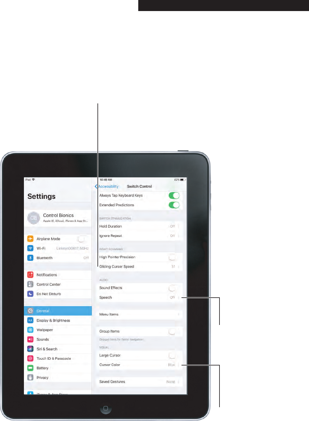
5.2 Switch Control Settings
Gliding Cursor Speed:
The speed, from 1 (slow) to 100 (fast),
at which the gliding cursor moves
across the screen.
Use this setting to adjust the
speed while in Point Mode.
Cursor Color:
This setting controls the
color of the gliding cursor
in Point Mode or the color
of the grouped items in
Item Mode.
Speech:
This switch turns on/off
Audio cues during
scanning.
PAGE 28┃ACCESSIBILITY SETTINGS

5.3 Setting an Accessibility Shortcut
Accessibility Shortcut:
Select the Accessibility
Shortcut and then select
“Switch Control.” This
allows the user to turn
Switch Control On and Off
by pressing the Home
Button three times in quick
succession.
Setting an Accessibility Shortcut provides a quick,
efficient way to turn Switch Control On and Off without
entering the system settings.
In order to do this, open the Accessibility Settings by
following steps 1-3 in Section 4.4 and then follow the
instructions below.
PAGE 29┃ACCESSIBILITY SETTINGS
In some circumstances it may be necessary to restart
and re-pair the NeuroNode to the device. In order to do
so, follow these steps:
1. Turn off Switch Control.
2. Remove the NeuroNode battery.
3. Swipe close the NeuroNode Application.
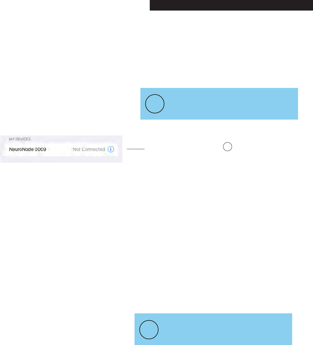
4. Go to Settings – Bluetooth.
5. If applicable, click on the next to the NeuroNode
device and select “Forget This Device.”
6. Turn off Bluetooth.
7. Upon performing a power cycle on the NeuroNode,
the device will go through a launch sequence as a
series of colors: red, green, blue, and white. During
this 5 second launch sequence use the provided push
pin to hold down the Threshold Button until a blue
light begins to flash on the Signal Indicator.
See section 6.2 for detailed instructions on performing a
power cycle.
8. After the blue light stops flashing, the launch
sequence should begin again, after which a solid
light will indicate the current threshold setting.
9. Turn on the device Bluetooth.
10. Ensure the NeuroNode is listed in the Bluetooth
“OTHER DEVICES” list.
11. Launch the NeuroNode Controller Application and
select “Connect to the NeuroNode.”
12. Upon receiving a NeuroNode Pairing request, select
“Pair.”
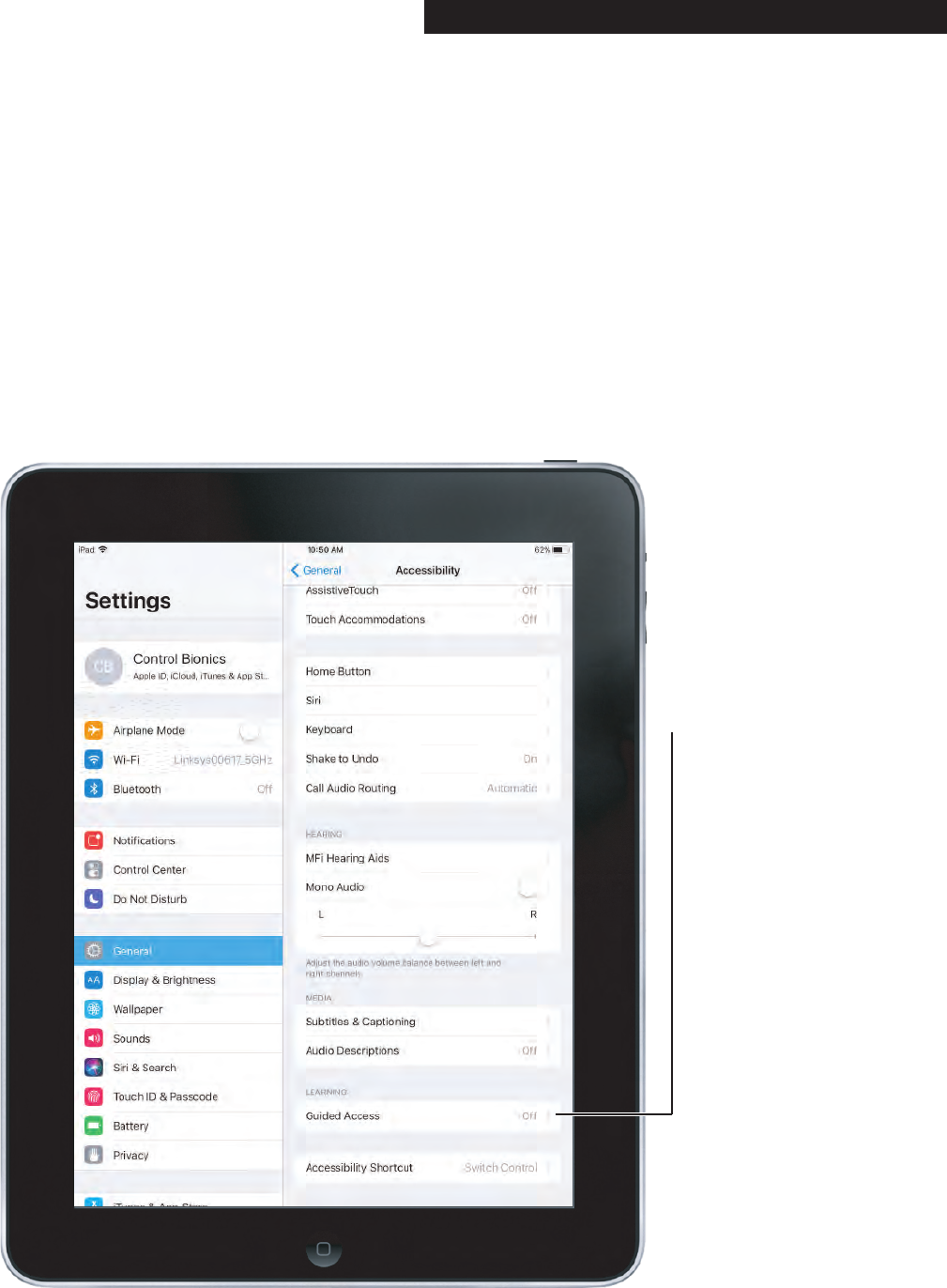
5.4 Setting Up Guided Access
Guided Access:
Follow steps 1-3 in
Section 4.4 then select
Guided Access to turn
Guided Access on and
off.
Guided Access can limit an iOS device to a single
Application and allow the user to control which Applica-
tion features are available.
With Guided Access the user is able to temporarily
restrict an iOS device to a single Application and, more
importantly, to disable areas of the screen where an
accidental gesture or selection may cause an unwanted
action.
PAGE 30┃ACCESSIBILITY SETTINGS
5.5 Changing from Point Mode to Item Mode
The default Switch Control scanning mode is Item
Mode.
Item Mode highlights items or groups on the screen
one at a time.
Point Mode allows selection of an item on the screen by
pinpointing it with scanning crosshairs.
Follow the steps in this section to change from one
scanning mode to the other.
PAGE 31┃ACCESSIBILITY SETTINGS
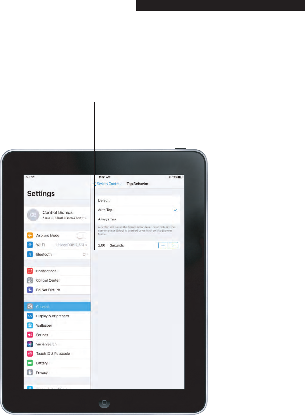
5.5 Changing from Point Mode to Item Mode
In order to access the Scanner Menu, first adjust the
timing parameters within the Switch Control Tap
Behavior Settings.
To access Switch Control Tap Behavior settings, follow
steps 1-4 outlined in section 4.4, then select Tap
Behavior.
Step 1:
The default Control Bionics
setting is Auto Tap set to
0.20 seconds. Adjust this
timing to 2.00 seconds.
PAGE 32┃ACCESSIBILITY SETTINGS
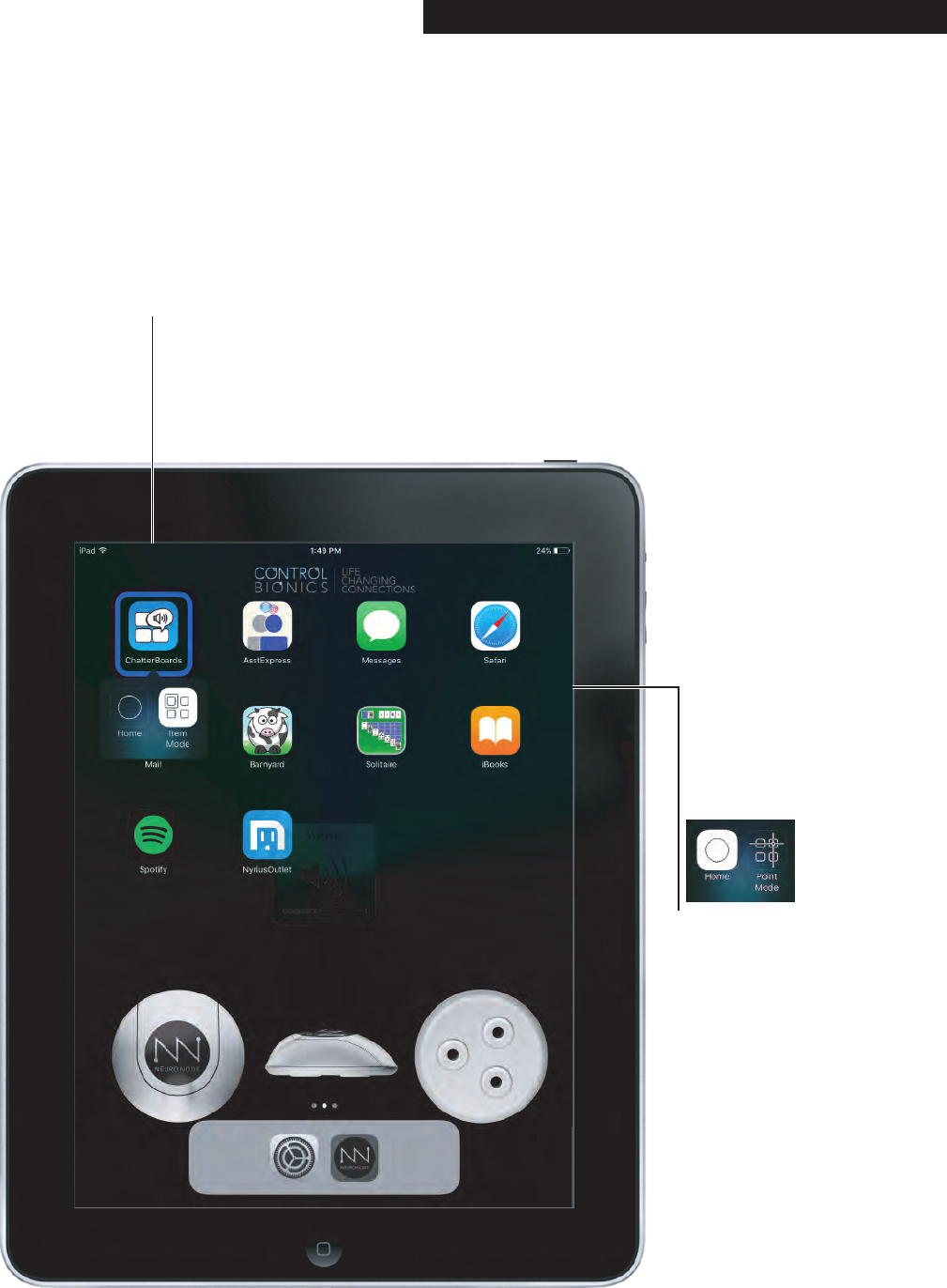
5.5 Changing from Point Mode to Item Mode
Step 2:
Scan to and select any item
on the iPad. Once an item is
selected, make another switch
within 2 seconds to display the
Scanner Menu.
Step 3:
Scan to and select
Item Mode.
If in Item Mode,
scan to and select
Point Mode.
PAGE 33┃ACCESSIBILITY SETTINGS
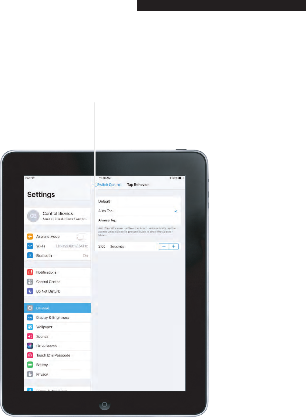
5.5 Changing from Point Mode to Item Mode
In order to increase overall speed, it may be helpful to
return the Switch Control Tap Behavior settings back to
their original settings.
To access Switch Control Tab Behavior settings, follow
steps 1-4 outlined in section 4.4, then select Tap
Behavior.
Step 4:
The default Control Bionics
setting is Auto Tap. Adjust this
timing back to 0.20 seconds.
PAGE 34┃ACCESSIBILITY SETTINGS
In some circumstances it may be necessary to restart
and re-pair the NeuroNode to the device. In order to do
so, follow these steps:
1. Turn off Switch Control.
2. Remove the NeuroNode battery.
3. Swipe close the NeuroNode Application.
4. Go to Settings – Bluetooth.
5. If applicable, click on the next to the NeuroNode
device and select “Forget This Device.”
6. Turn off Bluetooth.
7. Upon performing a power cycle on the NeuroNode,
the device will go through a launch sequence as a
series of colors: red, green, blue, and white. During
this 5 second launch sequence use the provided push
pin to hold down the Threshold Button until a blue
light begins to flash on the Signal Indicator.
See section 6.2 for detailed instructions on performing a
power cycle.
8. After the blue light stops flashing, the launch
sequence should begin again, after which a solid
light will indicate the current threshold setting.
9. Turn on the device Bluetooth.
10. Ensure the NeuroNode is listed in the Bluetooth
“OTHER DEVICES” list.
11. Launch the NeuroNode Controller Application and
select “Connect to the NeuroNode.”
12. Upon receiving a NeuroNode Pairing request, select
“Pair.”
TO SWIPE CLOSE AN APPLICATION,
DOUBLE CLICK THE HOME BUTTON AND
SWIPE UP ON THE APPLICATION.
!
DO NOT PAIR THE NEURONODE WHILE IN
BLUETOOTH PREFERENCES.
!
i
6.0 Trouble Shooting 6.1 NeuroNode Reset and Re-Pair Guide
PAGE 35┃TROUBLE SHOOTING

6.2 NeuroNode Power Cycle Guide
If the NeuroNode Controller Application has been
accidentally closed while using the NeuroNode, or if the
NeuroNode has traveled outside of the iPad’s Bluetooth
range while the NeuroNode Controller Application is
running it may be necessary to perform a power cycle or
temporarily shim the battery. In order to do this, follow
these steps:
1. In the NeuroNode Controller Application Settings,
select “Disconnect.”
2. Carefully remove the battery cover on the NeuroNode.
3. To initiate a power cycle, insert and then remove the
collar stay, or shimming tool, from in between the
battery top and the “+” terminal spring.
5. The initiating lighting sequence should begin,
indicating a repowered NeuroNode. Carefully replace
the battery cover on the NeuroNode.
6. Return to the NeuroNode Controller Application and
select “Connect to NeuroNode.”
PAGE 36┃TROUBLE SHOOTING
+
+
LIR2032
3.6v
L
I
-
I
O
N
R
E
C
H
A
R
G
E
A
B
L
E
B
A
T
T
E
R
Y

6.3 NeuroNode Battery Changing Guide
As time passes, it will be necessary to change the
NeuroNode battery.
A low battery will be indicated on the Signal Indicator by a
yellow flashing light, at which point the user has approxi-
mately 15 minutes to change the battery. During this 15
minutes the NeuroNode will still be usable.
If the battery voltage is too low for use in the NeuroNode,
it will be indicated on the Signal Indicator by a solid
yellow light. The NeuroNode will not be usable while this
light is displayed.
In order to ensure this does not disrupt the user’s connec-
tion, follow these steps:
1. In the NeuroNode Controller Application Settings
select “Disconnect.”
2. Carefully remove the battery cover on the NeuroNode.
3. Gently lift the discharged battery upward and slide it
out from beneath the “+” terminal spring.
4. Place a fully charged lithim-ion battery beneath the “+”
terminal spring, with the positive side facing up.
5. The initiating lighting sequence should begin,
indicating a powered NeuroNode. Carefully replace the
battery cover on the NeuroNode to start or continue
the session.
6. Return to the NeuroNode Controller Application and
select “Connect to NeuroNode.”
PAGE 37┃TROUBLE SHOOTING

WHILE IN PAUSE MODE, SWITCH CONTROL
WILL NOT RESPOND TO THE NEURONODE.
!
6.4 Ending a NeuroNode Session
At times it will be helpful to pause or end a current
NeuroNode session in order to resume at a later time. In
order to ensure this does not disrupt the user’s connec-
tion, follow these steps:
1. In the NeuroNode Controller Application Settings,
select “Disconnect.”
2. Carefully remove the battery cover on the NeuroNode.
3. Gently lift the discharged battery upward and slide it
out from beneath the “+” terminal spring.
4. Carefully replace the battery cover on the NeuroNode.
6.5 Resuming a NeuroNode Session
In order to resume a NeuroNode session, follow these
steps:
1. Carefully remove the battery cover on the NeuroNode.
2. Place a fully charged, lithim-ion battery beneath the
“+” terminal spring, with the positive side facing up.
3. The initiating lighting sequence should begin,
indicating a powered NeuroNode. Carefully replace
the battery cover on the NeuroNode to start or
continue the session.
4. Return to the NeuroNode Controller Application and
select “Connect to NeuroNode.”
6.6 Pause/Play a NeuroNode Session
At times it will be helpful to temporarily Pause a
NeuroNode session. This may be useful when the user is
being repositioned or transfered. This setting is also useful
when a caregiver or a Control Bionics Team member is
adjusting the user’s Switch Control settings.
If pausing a session for more than an hour, it is recom-
mended you follow the procedure for Ending a
NeuroNode Session, section 6.4.
To enable Play/Pause on the NeuroNode Controller
Application simply press the Play/Pause button.
PAGE 38┃TROUBLE SHOOTING
In order to disconnect the NeuroNode from the iPad
and pair the NeuroNode to a different device, follow
these steps:
1. Turn off Switch Control.
2. Remove the NeuroNode battery.
3. Close the NeuroNode Application.
4. Go to Settings – Bluetooth.
5. If applicable, click on the next to the NeuroNode
device and select “Forget This Device.”
6. Turn off Bluetooth.
7. Upon performing a power cycle on the NeuroNode,
the device will go through a launch sequence as a
series of colors: red, green, blue, and white. During
this 5 second launch sequence use the provided push
pin to hold down the Threshold Button until a blue
light begins to flash on the Signal Indicator.
See section 6.2 for detailed instructions on performing a
power cycle.
8. After the blue light stops flashing, the launch
sequence should begin again, after which a solid
light will indicate the current threshold setting.
9. Consult the new device’s instructions for pairing the
NeuroNode as a Bluetooth input device and utilizing
the NeuroNode as a switch within the device’s
application.
TO SWIPE CLOSE AN APPLICATION,
DOUBLE CLICK THE HOME BUTTON AND
SWIPE UP ON THE APPLICATION.
!
PLEASE CONTACT US AT 1-513-453-4848
FOR ANY ASSISTANCE.
!
i
PAGE 39┃TROUBLE SHOOTING
6.7 Pairing the NeuroNode to a New Device