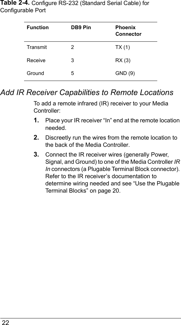
Control4 AVMMC11 Model AVM-MC1-B Media Controller User Manual MediaController
Control4 Model AVM-MC1-B Media Controller MediaController
UserManual.wiki
>
Control4
>
AVMMC11 User Manual
Exhibit 8
Navigation menu
Upload a User Manual
Namespaces
Wiki Guide
HTML
PDF
Info
Views
User Manual
Discussion / Help
Navigation

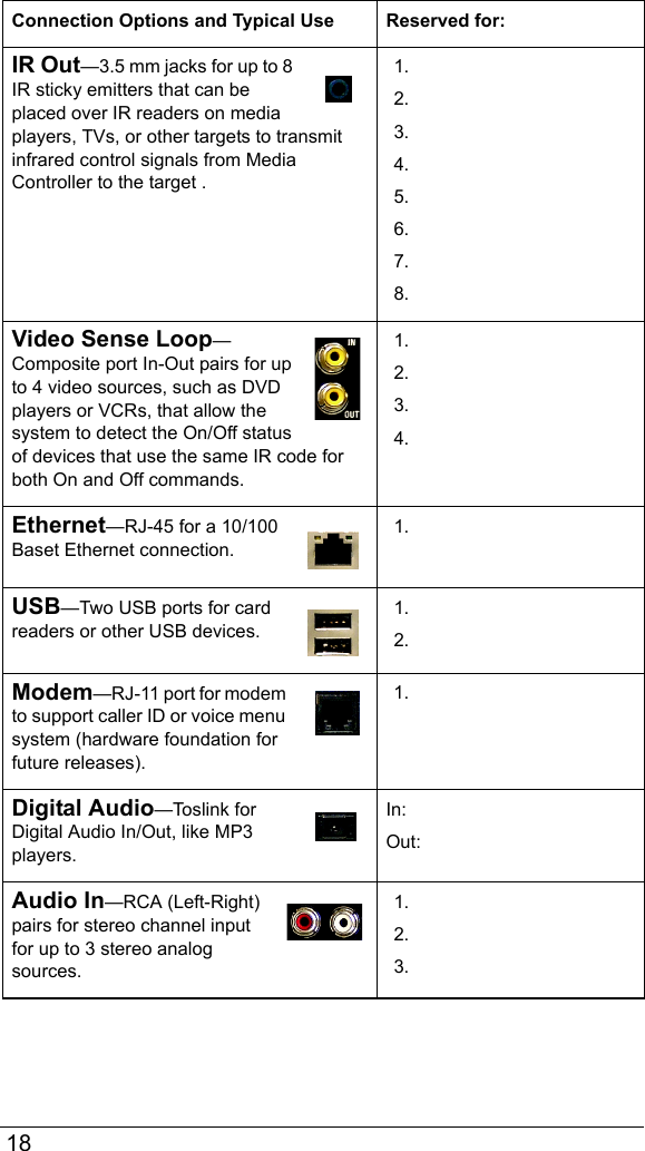

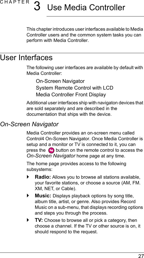
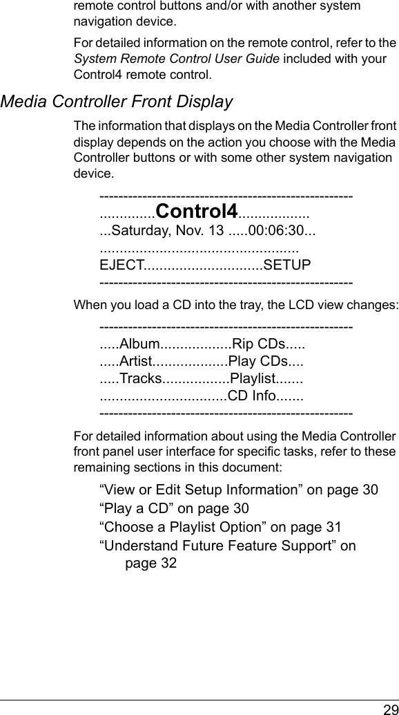
![28`Videos: Displays movie-playing options when a controlled DVD player or changer has been included in the system.`Comfort: Allow you to control all comfort related devices, such as a thermostat, radiant heating, fans, curtains and blinds, and a fireplace. It can also display the current indoor temperature.`Lights: Provides a list of rooms from which you choose to view controls for the lights and lighting scenes for that room.`House: Diplays control options for miscellaneous home control features, with an emphasis on security (such as door locks, motion sensors, contact sensors, and cameras). But may also control sprinklers, and communication information (like Caller ID).`Info: Displays your personal profile and options for this navigator (the selected controller, room, and appearance and other options available). You might also find organization (calendar) information and tools (maybe wizards) for managing devices and events.`Location: Set the room location and associated controller for this navigator option. [Does this differ from “View or Change Info”?].For detailed information about using On-Screen Navigator, refer to the On-Screen Navigator User Guide.System Remote Control with LCDThe Control4 System Remote Control that ships with Media Controller includes a liquid crystal display (LCD), in addition to a variety of buttons for accessing and controlling system components and media. The information that displays on the remote control LCD depends on the action you choose with the](https://usermanual.wiki/Control4/AVMMC11/User-Guide-513582-Page-32.png)