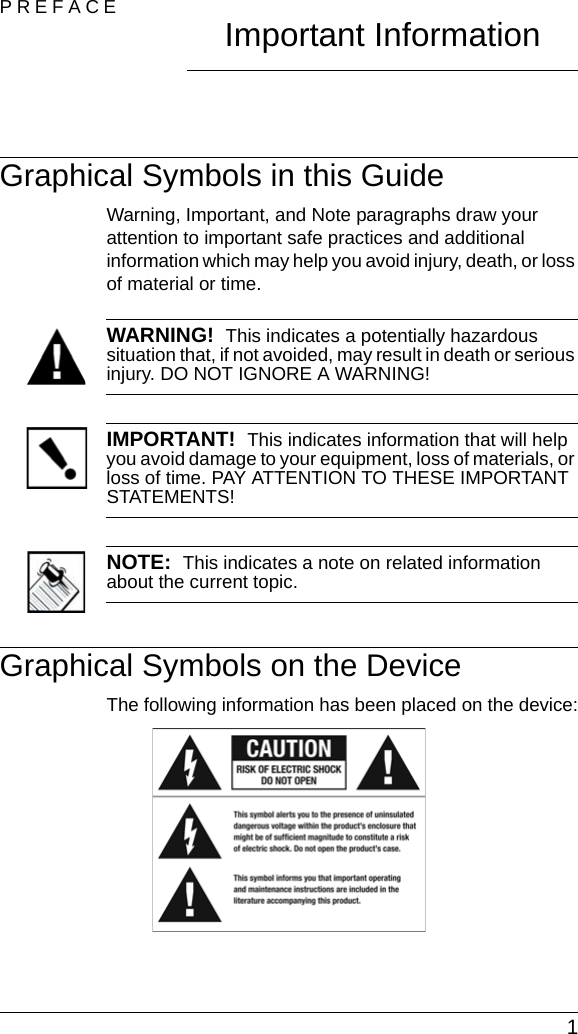
Control4 C416AMP3 Multi Channel Amplifier User Manual 200 00038 Rev A MultiChannelAmp
Control4 Multi Channel Amplifier 200 00038 Rev A MultiChannelAmp
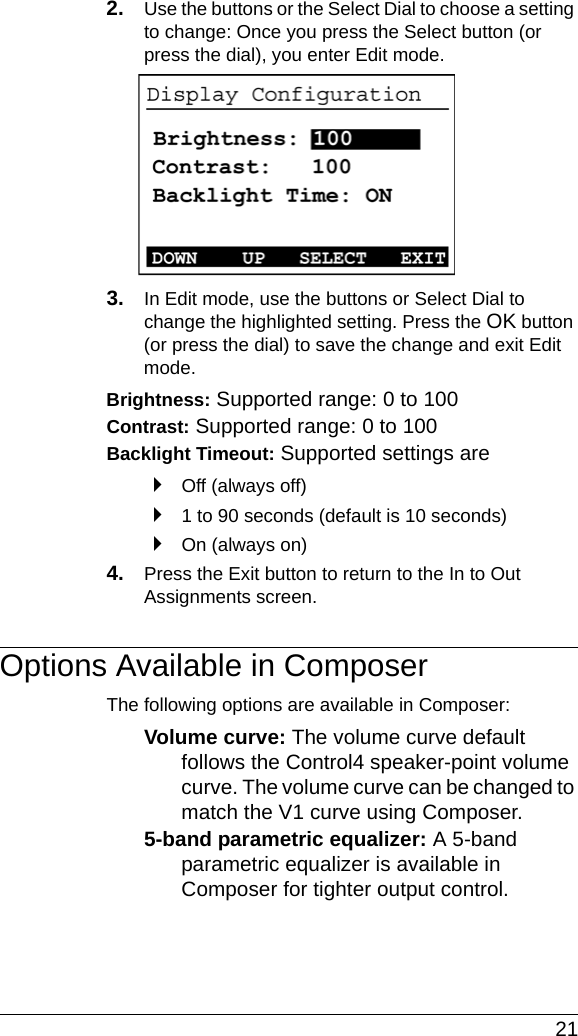
UserManual.wiki
>
Control4
>
C416AMP3 User Manual
Exhibit 8
Navigation menu
Upload a User Manual
Namespaces
Wiki Guide
HTML
PDF
Info
Views
User Manual
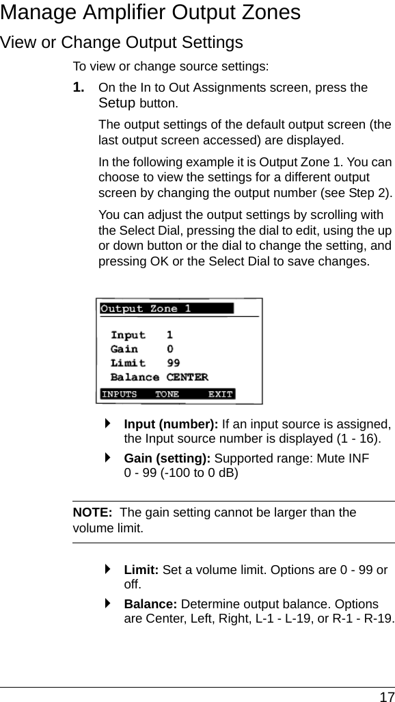
Discussion / Help
Navigation