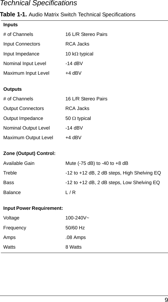
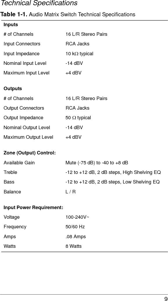
Control4 C416S2EB Audio Matrix Switch - 16 User Manual 200 00039 AudioMatrixSwitch

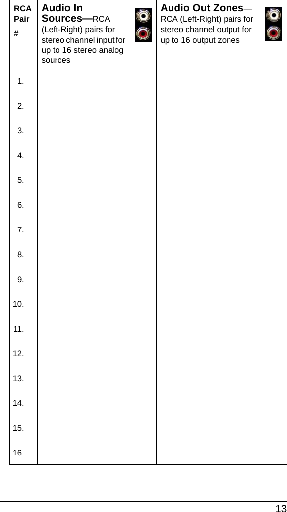
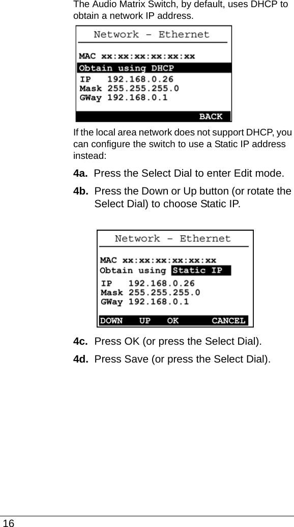
Control4 Audio Matrix Switch - 16 200 00039 AudioMatrixSwitch

Exhibit 8

DisclaimerControl4® makes no representations or warranties with respect to this publication, and specifically disclaims any express or implied warranties of merchantability or fitness for any particular purpose. Control4 reserves the right to make changes to any and all parts of this publication at any time, without any obligation to notify any person or entity of such changes.TrademarksControl4 and the Control4 logo are trademarks or registered trademarks of Control4 Corporation. Other product and company names mentioned in this document may be the trademarks or registered trademarks of their respective owners.Copyright Copyright © 2004-2008 Control4. All rights reserved. No part of this publication may be reproduced, photocopied, stored on a retrieval system, or transmitted without the express written consent of the publisher.Contact UsControl4 Corporation11734 S. Election RoadSalt Lake City, UT 84020 USAhttp://www.control4.comAudio Matrix Switch - 16 Installation and User GuidePart Number: 200-00039 Rev C (Draft 2)Hardware Model Number: C4-16S2-E-B
 iContentsPreface Important Information ....................................1Safety Instructions .................................1Graphical Symbols on the Device..........3Graphical Symbols in this Guide............3Additional Resources.............................4Chapter 1 Introduction to the Audio Matrix Switch .........5Features and Benefits............................5Network Requirements ..........................5What’s in the Box...................................6About the Audio Matrix Switch...............6Front View.........................................6Back View.........................................7Source Inputs.................................... 7Audio Outputs...................................7Front Display.....................................8Technical Specifications ...................9Chapter 2 Set Up the Audio Matrix Switch...................11Plan Your Physical Layout...................11Connect Input and Output Devices......14Connect to the Network and Power .....14Set Up Logical Connections ................14Network Configuration .........................15Chapter 3 Use Audio Matrix Switch..............................19View Output Assignments....................19Manage Outputs ..................................20View Output Assignments...............20Configure an Output .......................21Check Signal Status .......................22View Network Settings.........................23Set Front Display Preferences.............23
 iiChapter 4 Regulatory Compliance and Warranty.........25Regulatory Compliance .......................25FCC ................................................25Industry Canada .............................26Edison Test Lab (ETL)....................26CE Declaration of Conformity ......... 27Warranty ..............................................28Index .....................................................................................29
 1PREFACE Important InformationSafety Instructions1. Read these instructions.2. Keep these instructions.3. Heed all warnings.4. Follow all instructions.5. Do not use this apparatus near water.6. Clean only with dry cloth.7. Do not block any ventilation openings. Install in accordance with the manufacturer’s instructions.8. Do not install near any heat sources such as radiators, heat registers, stoves, or other apparatus (including amplifiers) that produce heat.9. Do not defeat the safety purpose of the polarized or grounding-type plug. A polarized plug has two blades with one wider than the other. A grounding-type plug has two blades and a third grounding prong. The wide blade or the third prong is provided for your safety. If the provided plug does not fit into your outlet, consult an electrician for replacement of the obsolete outlet.10. Protect the power cord from being walked on or pinched, particularly at plugs, convenience receptacles, and the point where they exit from the apparatus.11. Only use attachments/accessories specified by the manufacturer.12. Use only with the cart, stand, tripod, bracket, or table specified by the manufacturer, or sold with the apparatus. When a cart is used, use caution when
 2moving the cart/apparatus combination to avoid injury from tip-over.13. Unplug this apparatus during lighting storms or when unused for long periods of time.14. Refer all servicing to qualified service personnel. Servicing is required when the apparatus has been damaged in any way, such as when a power-supply cord or plug is damaged, liquid has been spilled or objects have fallen into the apparatus, the apparatus has been exposed to rain or moisture, does not operate normally, or has been dropped.WARNING!  Do not expose the apparatus to dripping or splashing. Do not place objects filled with liquids near the apparatus.WARNING!  To reduce the risk of fire or electrical shock, do not expose this apparatus to rain or moisture.WARNING!  Equipment must be connected to a Mains socket outlet with a protective earthing connection.
 3Graphical Symbols on the DeviceThe following information is placed on the device:Graphical Symbols in this GuideWarning, Caution, Note, and Tip paragraphs draw your attention to important safe practices and additional information which may help you avoid injury, death, or loss of material or time.WARNING!  This indicates a potentially hazardous situation that, if not avoided, may result in death or serious injury. DO NOT IGNORE A WARNING!CAUTION!  This indicates a potentially hazardous situation that, if not avoided, may result in minor or moderate injury. DO NOT IGNORE A CAUTION!
 4IMPORTANT!  This indicates information that will help you avoid damage to your equipment, loss of materials, or loss of time. PAY ATTENTION TO THESE IMPORTANT STATEMENTS!NOTE:  This indicates a note on related information about the current topic. TIP:  This indicates a tip that may save you time or effort.Additional ResourcesThe following resources are available:`Your Control4-authorized reseller`Control4 Web Site: http://www.control4.com/
 5CHAPTER 1Introduction to the Audio Matrix SwitchControl4 systems are uniquely configured for every customer and every site. A popular component among music lovers is the Control4 Audio Matrix Switch. This chapter introduces the Control4 Audio Matrix Switch and its features.Features and Benefits`Switches up to 16 input sources to up to 16 simultaneous output zones.`Adjustable gain, treble, bass, and balance for each zone`Audio sensing on inputs`Device chassis is three standard rack units (RU) tall and rack mountable conforming to EIA 19” rack standards (5.25” x 17.34” x 14”)`Communicates with control devices via Ethernet 10/100 port and ZigBee (a wireless standard for mesh-networking).`Backlighting feature turns on with any button push or Select Dial push and stays lit for a preset time (default is 30 seconds). Network RequirementsIn order for the Audio Matrix Switch to be managed and controlled from the Control4 user interfaces, it must communicate with the system through either a wired (Ethernet) or wireless (ZigBee 802.15.4 mesh) network. If you want to use an Ethernet connection for the Audio
 6Matrix Switch, ensure that your home network wiring is in place before starting system setup.What’s in the BoxThe following items are included in your Control4 Audio Matrix Switch box.`Control4 Audio Matrix Switch`IEC power cord`This manualAbout the Audio Matrix SwitchFront View1.  Front Display—For displaying or setting audio switch settings and navigating system menus2.  Buttons—For choosing options or menus displayed in the front panel user interface3.  Select Dial—For scrolling through and selecting screen elements or options displayed in the LCD123
 7Back View 1.  Power Plug Port—For standard IEC cord (included). Supports universal AC input (100-240 VAC 50/60 Hz).2.  Ethernet—RJ-45 for a 10/100 Mb Ethernet connection3.  Audio In (Left-Right pairs) 1-16—RCA jacks for stereo channel input for up to 16 stereo analog sources4.  Audio Out (Left-Right pairs) 1-16—RCA jacks for stereo channel line output for up to 16 amplifiersSource InputsEach of the 16 signal sensing analog audio inputs (the RCA style ports) is labeled 1-16 for each individual source. Audio OutputsThe system automatically creates generic source names displayed in the front of the device. To change these names, you must update your system using supported system designing software (such as Composer Pro on a PC). For more information, refer to the documentation that shipped with your Control4 controller or contact your professional installer or reseller.1234
 8Front DisplayThe best method of initially setting up system routing for the Audio Matrix Switch is using Composer Pro software on a PC (for trained installers only). You can also make adjustments from the front display.The front display allows you to set or change audio source routing and change zone settings for volume, bass, treble, and mute. The display also shows the current source and zone activity.
 9Technical SpecificationsTable 1-1. Audio Matrix Switch Technical SpecificationsInputs# of Channels 16 L/R Stereo PairsInput Connectors RCA JacksInput Impedance 10 kΩ typicalNominal Input Level -14 dBVMaximum Input Level +4 dBVOutputs# of Channels 16 L/R Stereo PairsOutput Connectors RCA JacksOutput Impedance 50 Ω typicalNominal Output Level -14 dBVMaximum Output Level +4 dBVZone (Output) Control:Available Gain Mute (-75 dB) to -40 to +8 dBTreble -12 to +12 dB, 2 dB steps, High Shelving EQBass -12 to +12 dB, 2 dB steps, Low Shelving EQBalance L / RInput Power Requirement:Voltage 100-240V~Frequency 50/60 HzAmps .08 AmpsWatts 8 Watts
 10
 11CHAPTER 2Set Up the Audio Matrix SwitchThis device operates as part of the Control4 home system, which requires physical and logical connections to function as designed.Essential setup tasks include: 1.Plan Your Physical Layout2.Connect Input and Output Devices3.Connect to the Network and Power4.Set Up Logical Connections5.Static IP ModificationsThis chapter describes, in general terms, how to set up physical connections required for the Audio Matrix Switch and all associated devices. Refer to any device-specific documentation for additional installation instructions.To set up the logical connections required, refer to Control4 Composer Pro User Guide software documentation.Plan Your Physical LayoutThis section explains physical and logical connections and can help you plan your physical connections.Use a worksheet to plan your audio zones. Using the worksheet provided in Table 1 on page 12, identify the ports you will use for each planned devices and zones.
 12Table 1: Audio Matrix Switch Routing Worksheet
 13RCA Pair #Audio In Sources—RCA (Left-Right) pairs for stereo channel input for up to 16 stereo analog sourcesAudio Out Zones—RCA (Left-Right) pairs for stereo channel output for up to 16 output zones1.2.3.4.5.6.7.8.9.10.11.12.13.14.15.16.
 14Connect Input and Output Devices1. Connect audio source devices (such as CD changers or players, tuners, iPods, or tape players) you want included in the system to the audio in jacks. 2. Connect amplifiers or amplified speakers as needed to the audio out jacks. NOTE:  If you are not sure which jacks to use, try using the worksheet provided in Table 1 to plan your routes. Connect to the Network and Power1. If you are using an Ethernet connection for the Audio Matrix Switch, plug the data cable from the home network connection into the Audio Matrix Switch RJ-45 port (labeled Ethernet) and the network port in your wall or at the network hub or switch.2. Connect the power cord provided to the back of the Audio Matrix Switch and to the power outlet. Once the power cord is connected, the Audio Matrix Switch should power up.Set Up Logical ConnectionsPhysical and logical connections are required in order to control, navigate, and use the Audio Matrix Switch as designed. Thus far you have set up the physical connections for the Control4 Audio Matrix Switch. To complete the logical setup, trained installers must use a PC connected (and with Control4 Composer software installed) to the home network. If you are a trained Control4 installer, refer to the Control4 Composer User Guide.
 15Network ConfigurationTo set the network configuration: 1. At the In to Out Assignments screen, press the Network button.2. On the Network Configuration screen, choose an Ethernet or ZigBee network by rotating and pressing the Select Dial.IMPORTANT! When making logical connections in Composer, identify the device as the network type (Ethernet or Zigbee) that you choose on the device network configuration. To avoid unexpected behavior, do not identify the device as both network types.3. If the switch is set to use a ZigBee network, the EUID, Gateway, and ZigBee channel number are displayed.This screen has two menu options:`Identify: When identifying the switch in Composer, press this button.`Back: Returns to the Network Configuration screen.4. If the switch is set to use an Ethernet network, the MAC address, method of obtaining a network IP address, the device’s IP address, Subnet Mask, and Gateway are displayed.
 16The Audio Matrix Switch, by default, uses DHCP to obtain a network IP address. If the local area network does not support DHCP, you can configure the switch to use a Static IP address instead:4a.  Press the Select Dial to enter Edit mode.4b.  Press the Down or Up button (or rotate the Select Dial) to choose Static IP.4c.  Press OK (or press the Select Dial).4d.  Press Save (or press the Select Dial).
 174e.  Edit the IP, Mask, and GWay fields for the Static IP network: Use the Select Dial to select a line, then press the dial.Use the Select Dial to scroll the number up or down and edit as needed, then press the Select Dial to move to the next field within the number.4f.   When finished editing, press Save.
 18
 19CHAPTER 3Use Audio Matrix SwitchThis chapter introduces the user interface available to Audio Matrix Switch users and common system tasks you can perform with the Audio Matrix Switch from the front display.NOTE:  Following initial setup, you may never need to manually change settings on the Audio Matrix Switch. This device is managed by the Control4 system. The use of this chapter is completely optional.This device assists in fulfilling a room-specific music request. To play music, use a system navigation device available to your current room to choose a specific music source or a device. That device may or may not need to make use of this switch.View Output AssignmentsOnce you complete the physical and logical setup tasks, you can view or change setup configuration in the Audio Matrix Switch front display. When you power up the Audio Matrix Switch, the following System Status screen appears momentarily.The System Status screen is then replaced by the In to Out Assignments screen.
 20Once you make an assignment, the screen displays the assignment. For example, Output 1 is mapped to Input 1.Manage OutputsView Output AssignmentsTo view output assignments:1. Ensure your Audio Matrix Switch is powered up and that the In to Out Assignments screen displays in the front display.2. On the In to Out Assignments screen, view the current input-to-output assignments.The screen consists of 16 output zones and any assigned input source. The shaded arrow indicates the Output currently selected.
 21To explore these menu options, press the buttons on the front panel:`Setup: Displays an output-specific screen. The most recent screen accessed is displayed by default, but you can choose to view a different output’s setting by changing the Output number. `Network: Displays the Network Configuration screen. From this screen, you can select Ethernet or Zigbee.`Display: Displays the Display Configuration Screen.Configure an OutputTo change output source or settings:1. On the Output to Input screen, press the Setup button to view the output settings of the default output screen (which is the last output screen accessed).From the output screen, you can: (1) change to another output screen; (2) change the output settings on the screen; or (3) toggle to the Input Signal Sensing screen.1a.  If the output-specific screen you want to view did not display, use the Select Dial to highlight and select the output number and then change it.1b.  (Optional) Change settings for the current output using the supported ranges:`Input: Displays the number of the currently assigned input source and any label given to the input source. You can change this setting to any available input sources.
 22`Gain: Supported range: Mute and -44 to +4 dB (default: 0 dB)`Treble: Supported range: -12 to +12 dB (default: 0 dB)`Bass: Supported range: -12 to +12 dB (default: 0 dB)`Balance: Supported range: -50 to +50dB (default: 0 dB)1c.  To toggle to view input signal sensing information, press the Inputs button. 1d.  To exit the screen, press the Exit button.2. Rotate the Select Dial to highlight a setting.3. Press the Select Dial to enter edit mode.4. Rotate the dial to change the setting; then press the dial to Save the new setting and exit edit mode or, to exit without saving, use the Cancel button.5. Press the Inputs button to go to the Input Signal Sensing screen, or press the Exit button to return to the Output to Input screen.Check Signal Status1. From the Output to Input screen, press the Setup button, then press the Inputs button to access the Input Signal Sensing screen.2. On the Input Signal Sensing screen, a shaded circle appears by the device connection number of any input device with a signal present.
 23View Network SettingsTo view network settings:1. Press Network. 2. From the Network Configuration screen, select Ethernet or Zigbee.3. To return to the Network Configuration screen, press Back. Set Front Display PreferencesTo set your viewing preferences for the front display:1. On the Output to Input screen, press the Display button. The Display Configuration screen displays.Use the buttons and/or the Select Dial to choose a setting to change: Once you press the Select button (or press the dial), you enter Edit mode.2. In Edit mode, use the buttons or Select Dial to change the highlighted setting then press the OK button (or press the dial) to save the change and exit.Brightness: Supported range: 0 to 100 Contrast: Supported range: 0 to 100 Backlight Timeout: Supported settings are: `OFF (always off)`1 to 90 seconds (default is 30 seconds)`ON (always on)Reset Defaults: Restores factory defaults.
 24
 25CHAPTER 4Regulatory Compliance and WarrantyRegulatory ComplianceThis product complies with standards established by the following regulatory bodies:Federal Communications Commission (FCC)Industry CanadaUnderwriters Laboratories Inc. (UL)CEFCC FCC ID: R33C416S2EBThis device complies with Part 15 of the FCC Rules. Operation is subject to the following two conditions: (1) This device may not cause harmful interference, and (2) this device must accept any interference received, including interference that may cause undesired operation.This equipment has been tested and found to comply with the limits for a Class B digital device, pursuant to Part 15 of the FCC Rules. These limits are designed to provide reasonable protection against harmful interference in a residential installation. This equipment generates uses and can radiate radio frequency energy and, if not installed and used in accordance with the instructions, may cause harmful interference to radio communications. However, there is no guarantee that interference will not occur in a particular installation. If this
 26equipment does cause harmful interference to radio or television reception, which can be determined by turning the equipment off and on, the user is encouraged to try to correct the interference by one of the following measures:`Reorient or relocate the receiving antenna.`Increase the separation between the equipment and receiver.`Connect the equipment into an outlet on a circuit different from that to which the receiver is connected.`Consult the dealer or an experienced radio/TV technician for help.IMPORTANT!  Changes or modifications not expressly approved by Control4 could void the user’s authority to operate the equipment.Industry CanadaThis Class B digital apparatus complies with Canada ICES-003.Cet appareil numérique de la classe B est conforme à la norme NMB-003 du Canada.Edison Test Lab (ETL)This product has been tested by ETL and has been found to be in compliance with:`UL 60065, Second Edition, “Standard for Audio/Video and Electronic Equipment” `CSA C22.2 No. 60065-03, First Edition: 2006, “Audio, Video and Similar Electronic Equipment”
 27CE Declaration of ConformityProduct: Audio Matrix Switch (Model # C4-16S2-E-B)The undersigned hereby declares, on behalf of Control4 Corporation, that the above-referenced product, to which this declaration relates, is in conformity with the provisions of:`Council Directive 89/336/EEC (May 3, 1989) on Electromagnetic Compatibility`Council Directive 1999/5/EC (Mar 9, 1999) on Radio & Telecommunication Terminal Equipment (R&TTE)`Council Directive 73/23/EEC (Feb. 19, 1973) on Low Voltage Equipment Safety`Council Directive 93/68/EEC (Jul. 22, 1993) Amending Directives 89/336/EEC and 73/23/EECand has been tested to the requirements of, and shown to be in compliance with, the following requisite standards:`EN 300-328 V1.7.1 (2006-10), Electromagnetic Compatibility and Radio Spectrum Matters (ERM); wide band transmission systems; data transmission equipment operating in the 2.4 GHz ISM band and using wide band modulation techniques.`EN 55024:1998 incorporates: EN61000 (4-2, 4-3, 4-4, 4-5, 4-6, 4-8, 4-11 and A1 & A2)`EN 61000-3-2:2005, Limits for harmonic current emissions`EN 61000-3-3:2002, Limitation of voltage fluctuations and flicker in low voltage supply systemsThe Technical Construction File required by these Directives is maintained at the corporate headquarters of Control4, Salt Lake City, Utah, U.S.A.Signed, Brett Molen—Vice President, Engineering, June 6, 2008European Contact InformationControl4 UK LimitedUnit 3, Green Park Business CentreSutton-on-the-Forest, YorkYO61 IET, United Kingdom+44 (0) 134781 2300, c4@control4-UK.comUnited States Contact InformationControl4 Corporation11734 S. Election Road, Suite 200Salt Lake City, UT 84020-6432, USATel (801) 523-3100
 28WarrantyThis device has a limited two (2) year warranty on parts from the date of purchase. Control4 will replace or repair any defective unit. Return unit to the place of purchase for replacement. For any damages incurred, the warranty will never exceed the purchase price of the device. This warranty does not cover installation, removal, or reinstallation cost. The warranty is not valid in cases where damage was incurred due to misuse, abuse, incorrect repair, or improper wiring or installation. It does not cover incidental or consequential damage. This warranty gives you specific legal rights, and you might also be entitled to other rights that vary from state to state. Some states do not allow limitations on how long an implied warranty lasts or the exclusion or limitation of incidental or consequential damages. In these cases, the above mentioned limitations might not apply to you. For complete warranty information, see www.control4.com/warranty.
 29IndexAAbout the Audio Matrix Switch 6Additional Resources 4AudioInputs 7Outputs 7Audio In 7Audio Matrix SwitchBack View 7Audio In 7Audio Out 7Ethernet 7Power Plug Port 7Front View 6Buttons 6Front Display 6Select Dial 6Audio Matrix Switch Routing Worksheet 12Audio Out 7BBack View 7Backlighting 5Buttons 6CCautions 3Check Signal Status 22Configure an Output 21Connect Input and Output Devices 14
 30Connect to the Network and Power 14DDisplay 21EEthernet 7, 15DHCP 15Static IP 16FFeatures and Benefits 5Front Display 6, 8Front View 6IInputConnect Input and Output Devices 14MManage Outputs 20View Output Assignments 20Display 21Network 21Setup 21NNetwork 21Ethernet 15, 16Requirements 5Settings 15Zigbee 15Network Configuration 15Notes 3
 31OOutputConfigure 21Connect Input and Output Devices 14Manage Outputs 20View Assignments 19PPlan Your Physical Layout 11Power Plug Port 7RRegulatory Compliance 25SSafety Instructions 1Select Dial 6Set Front Display Preferences 23Set Up Logical Connections 14Set Up the Audio Matrix Switch 11Setup 21Source 7Source Inputs 7Static IP 16TTechnical Specifications 9Tips 3UUse Audio Matrix Switch 19VView 19View Network Setting 23
 32View Output Assignments 19, 20WWarnings 3Warranty 25What’s in the Box 6ZZigbee 15

Navigation menu