Control4 C4APDKD ADAPTIVE PHASE DIMMER/KEYPAD DIMMER User Manual
Control4 ADAPTIVE PHASE DIMMER/KEYPAD DIMMER
UserManual.wiki
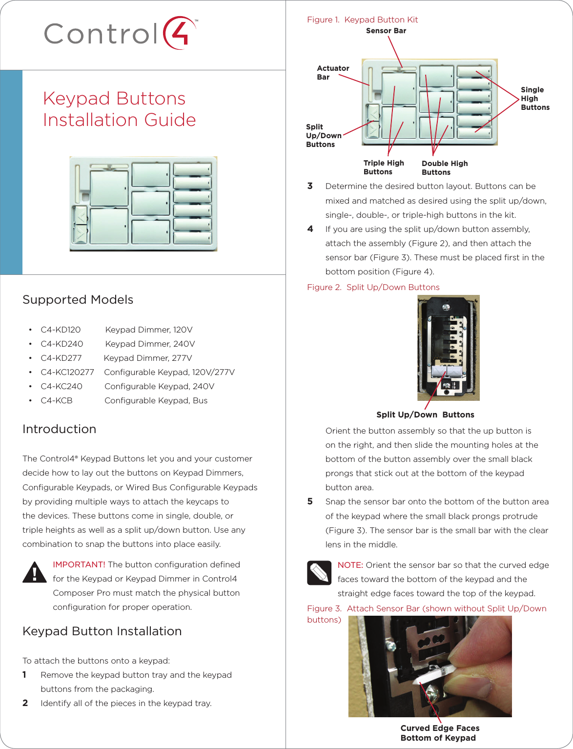
>
Control4
>
C4APDKD User Manual
USER MANUAL
Navigation menu
Upload a User Manual
Namespaces
Wiki Guide
HTML
PDF
Info
Views
User Manual
Discussion / Help
Navigation