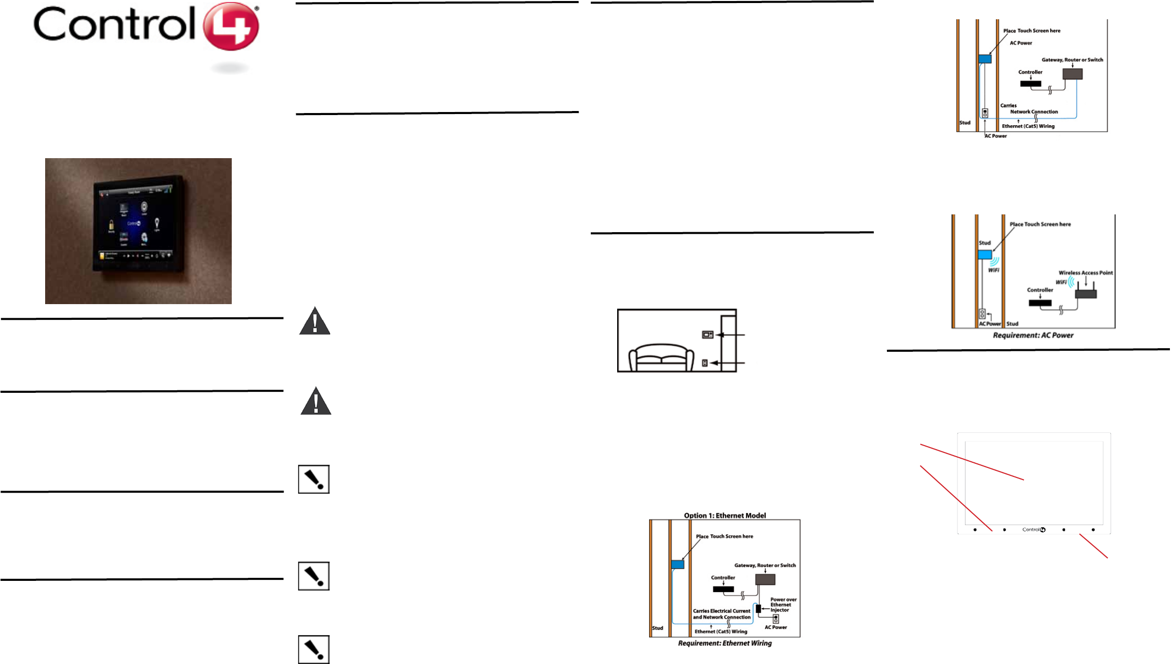
User manual

InnityEdge™ 5” and 7” In-Wall
Touch Screen
Installation Guide
Supported Models
• C4-TSWMC5–InnityEdge™5”In-WallTouchScreen
• C4-TSWMC7–InnityEdge™7”In-WallTouchScreen
•
AssociatedSKUs:
• C4-TSWMC5-EG-WH–InnityEdge™5”In-WallTouchScreen,White
• C4-TSWMC5-EG-BL–InnityEdge™5”In-WallTouchScreen,Black
• C4-TSWMC7-EG-WH–InnityEdge™7”In-WallTouchScreen,White
• C4-TSWMC7-EG-BL–InnityEdge™7”In-WallTouchScreen,Black
What’s in the Box
Carefullyunpackthecontentsofthebox,andmakesurethefollowingitemsareincluded
inthebox.Ifanyitemismissingordamaged,pleasecontactyourControl4Reseller.
• InnityEdge™5”or7”In-WallTouchScreen
• InnityEdge™powerbox(usedtopowertheTouchScreen)
• Two(2)Orangewirenuts
• InnityEdge™5”and7”In-WallTouchScreensInstallationGuide(thisdocument)
Important Safety Instructions
WARNING!TheTouchScreenmustbeprotectedbyanexternalcircuit
breakerorafuseratedat6AmaximumwhenusedinEurope.
Avertissement!Pourréduirelerisquedufeuoudechocélectrique,
n’exposezpascetappareilàlapluieouàl’humidité.
Warnung!DieBerührungseingabemußdurcheinenexternenCircuitbreaker
odereineSicherunggeschütztwerden,dieamMaximum6Averanschlagen
wird,wennsieinEuropaverwendetwird.
Important!Donotusepensorsharpobjectstonavigateormakeselec-
tionsontheTouchScreen.Toselectanitemorscrollthroughalist,useyour
ngertip.
Important!N’employezpaslesstylosoulesobjetspointuspourdirigerou
pourfairedeschoixsurl’écran.Pourchoisirunarticleouunrouleauparune
liste,employezvotreboutdudoigt.
Wichtig! BenutzenSienichtFedernoderscharfeGegenstände,umoder
VorwählerenaufdemSchirmzubildenzusteuern.UmeinEinzelteilodereine
RolledurcheineListevorzuwählen,benutzenSieIhreFingerspitze.
Important! ImproperuseorinstallationcancauseLOSS/DAMAGEOF
PROPERTY.
Important! L’utilisationoul’installationinexactepeutcauserLOSS/DAMAGE
DEPROPRIÉTÉ.
Wichtig!UnsachgemäßerGebrauchoderInstallationkönnenLOSS/DAM-
AGEDEREIGENSCHAFTverursachen.
Important! Usingthisproductinamannerotherthanoutlinedinthisdocu-
mentvoidsyourwarranty.Further,Control4isNOTliableforanydamage
incurredwiththemisuseofthisproduct.See“Warranty.”
Important!Utilisantceproduitenquelquesorteautrequedécritdansce
documentvidevotregarantie.Deplus,Control4n’estpasresponsable
d’aucundommageencouruavecl’abusdeceproduit.Voyezque«Warranty.»
Wichtig!DasVerwendendiesesProduktesingewissemSinneandersals
umrissenindiesemDokumenthebtIhreGarantieauf.WeiteristControl4
NICHTfürirgendeineBeschädigungverantwortlich,diemitderFehlanwend-
ungdiesesProduktesgenommenwird.SehenSie,daß“Warranty.”
Introduction
TheControl4® InnityEdge™5”or7”In-WallTouchScreensoffercompletesystemcontrol
inanelegantandcompactdesign.TheseTouchScreensareequippedwithacapacitive
TouchScreensurfaceandfour(4)programmableshortcutbuttons,andareavailablewith
ACpowerforwirelessconnectionsandPower-Over-Ethernet(PoE)forEthernetconnec-
tions.Availablefornewconstructionorretrots.
Accessories
• Control4PowerOverEthernetInjector,soldseparately(AC-POE1-B)
• InnityEdge™5”and7”In-WallTouchScreensWallBoxNewConstruction,Plastic
• (C4-NWB57C-P)
• InnityEdge™5”and7”In-WallTouchScreensWallBoxNewConstruction,Metal
• (C4-NWB57C-M)
• InnityEdge™5”and7”In-WallTouchScreensWallBoxRetrot,Plastic
(C4-RWB57C-P)
• InnityEdge™5”and7”In-WallTouchScreenWallBoxRetrot,Metal
(C4-RWB57C-M)
New Device
AC Power (unless using PoE)
Option 1: Ethernet Connection with a PoE Injector or a
Third-Party Injector or Switch
PoEinjectselectricalcurrentintotheEthernetcableusingaPoEInjector(model
#AC-POE1-B)orathird-partyPoEsolutiontoprovidetheTouchScreenwithpoweranda
networkconnection.TheInnityEdge™5”and7”TouchScreensworkwithaPoEInjector
orathird-partyPoEInjector.Ifyouplantouseathird-partyPoEsolution,see“Installa-
tion.”TosetupyourPoEandEthernetconnectionwithaPoEInjector,seeFigure2.
Figure 2. Ethernet Model - Requires Ethernet Connection to PoE Injector
PlacethePoEInjectornearyourgateway/router/switch.PulltheEthernetcablefromthat
locationtowhereyouwanttoinstalltheTouchScreen.
Option 2: Ethernet Connection with AC
NoPoEInjectorisneededforEthernetwithACpower;theEthernetisconnecteddirectly
totheswitch.Thispowerconnectionrequiresbothneutralandhotconnections(see
Figure3).
Option 3: WiFi Connection with AC
WiFiplacement:PlacetheTouchScreenaboveapowersource,suchasanoutlet.En-
surethatyouhaveWiFiinthehome(seeFigure4).
Figure 4. WiFi - Requires AC Power and WAP
Wall Box Kit Options
Therearefour(4)wallboxoptionsavailabletoinstallthisTouchScreen.Metalandplastic
wallboxesareavailablefornewconstructionorretrotinstallations.
• InnityEdge™5”or7”In-WallTouchScreenWallBoxKits-NewConstruction
PlasticModel(C4-NWB57C-P)
MetalModel(C4-NWB57C-M)
• InnityEdge™5”or7”In-WallTouchScreenWallBoxKit-Retrot
PlasticModel(C4-RWB57C-P)
MetalModel(C4-RWB57C-M)
RefertotheControl4InnityEdge5”or7”In-WallTouchScreenWallBoxInstallation
Guide-NewConstructionorInnityEdge5”or7”In-WallTouchScreenWallBoxInstalla-
tionGuide-Retrotforyourwallboxinstallationinstructions.
Placement, Network Connection, and Power
Options
PlacetheTouchScreeninaconvenientlocationateyelevel,typicallyneartheentranceof
theroom,approximately57to61inchesfromtheoor(seeFigure1).
WARNING!DonotplacetheTouchScreennearsourcesofheatorexposeto
directsunlightforanextendedperiodoftime.
Avertissement!Neplacezpasl’unitéprèsdessourcesdechaleurouexpo-
sitionpourdirigerlalumièredusoleilpendantunepériodeprolongée.
Warnung!SetzenSieMaßeinheitnichtnaheQuellenderHitzeoderdes
Exposés,umTageslichtwährendeinesausgedehntenZeitabschnittszu
verweisen.
ThisdeviceusesanEthernetnetworkconnectionwithPoEorWiFi,andcanbepowered
usingPoEorACpower.
Note:DonotattempttousePoEandACatthesametime.
Display:5”or7”viewingarea,TouchScreenwith800x480resolutionTFT.
Shortcut buttons (4):Forcustomprogramming;toinitiateanactionorsequenceof
actions.
Touch Screen Removal:SmallholelocatedundertheTouchScreentoremovethe
TouchScreenfromthewall.
Front dimensions:5”TouchScreen-(HxW):3.13”x4.75”(76.2mmx101.6mm);
7”TouchScreen-(HxW):6.00”x8.10”(152.4mmx205.7mm).
Wall box dimensions:5”and7”TouchScreens-(HxWxD):2.65”x4.06”x2.36”
(50.8mmx101.6mmx50.8mm).
1.
2.
3.
1
2
Front and Rear Panel Description
Front View
Figure 5. Front View of the InnityEdge 5” or 7” In-Wall Touch Screen
Figure 1. Touch Screen Placement
Requirements for In-Wall Installations
ToinstalltheInnityEdge™5”or7”TouchScreen,youneedthefollowing:
• HomeControllerHC-200,HC-300,HC-1000,CommercialControllerCC-300,or
CC-1000fullyinstalledandconguredwithaControl4®system.
• Control4InnityEdge™5”and7”TouchScreencustomwallboxinstalled.See“Wall
BoxKitOptions”inthisdocument.
• IfusingEthernetwithPoEpower:
• Ethernetnetwork.
• Control4PoEInjector(model#AC-POE1-B)oranotherthird-partyPoEInjectoror
switch.
• Two(2)EthernetCAT5cablestosupportyourPoEInjector:(1)onethatrunsfrom
theEthernetgateway/router/switchtothePoEInjector/switchand(2)onethatruns
fromthePoEInjector/switchtotheEthernetTouchScreenwallbox.
• IfusingEthernetwithACpower:
• AnEthernetnetworkinstalledandavailablethatincludesagateway/router/switch.
• Accesstoapoweroutlet.
• One(1)EthernetCAT5cablethatrunsfromtheEthernetgateway/router/switchto
theTouchScreen.
• IfusingwirelesswithACpower:
• Wirelessnetwork(WiFi802.11b/g)installedandavailablewithawirelessaccess
point(WAP).
• Accesstoin-wallACpower(aneutralconnectionisrequired).
• A14-gaugeelectricalwirelongenoughtopullbetweentheTouchScreenandthe
powersource.
ThisproductisalsodesignedforITpowersystemswithphase-to-phasevoltage
120Vor240V.
Donotinstallnearanyheatsourcessuchasradiators,heatregisters,stoves,or
otherapparatus(includingampliers)thatproduceheat.
Onlyuseattachments/accessoriesspeciedbyControl4.
Ifapplicable,unplugthisapparatusduringlightningstormsorwhenunusedforlong
periodsoftime.
Referallservicingtoqualiedservicepersonnel.Servicingisrequiredwhenthe
apparatushasbeendamagedinanyway,suchaspower-supplycordorplugisdam-
aged,liquidhasbeenspilledorobjectshavefallenintotheapparatus,theappara-
tushasbeenexposedtorainormoisture,doesnotoperatenormally,orhasbeen
dropped.
1.
2.
3.
4.
5.
6.
Readandkeeptheseinstructions.
Heedallwarningsandfollowallinstructions.
Donotusethisapparatusnearwater.
Cleanonlywithadrycloth.
Installinaccordancewiththemanufacturer’sinstructions.
Installinaccordancewithallnationalandlocalelectricalcodes.
7.
8.
9.
10.
11.
3
Figure 3. Ethernet - Requires Connection to Ethernet and AC Power

ProtectedunderU.S.Patents7,335,845,7,106,261andlicensedunderU.S.Patents
5,905,442and5,982,103
About this Document
©2010Control4.Allrightsreserved.Control4andtheControl4logoareregisteredtrade-
marksandInnityEdgeisatrademarkofControl4CorporationintheUnitedStatesand/or
othercountries.Allothernamesorbrandsmaybeclaimedaspropertybytheirrespective
owners.Pricingandspecicationssubjecttochangewithoutnotice.
PartNumber:200-00164RevE8/27/2010
Recycling
ForinformationaboutControl4’srecyclingprogram,goto:
www.control4.com/recycling.
Warranty
Limited2-yearWarranty.Refertohttp://www.control4.com/warranty.
Third-Party Trademarks
Libertas
LibertasFirmwarecopyrightstatementforTouchScreens6/26/09
Copyright(c)2006,OneLaptopperChildandMarvellCorporation.
Allrightsreserved.
Redistribution.Redistributionanduseinbinaryform,withoutmodication,arepermitted
providedthatthefollowingconditionsaremet:
*Redistributionsmustreproducetheabovecopyrightnoticeandthefollowingdisclaimer
inthedocumentationand/orothermaterialsprovidedwiththedistribution.
*NeitherthenameofMarvellCorporationnorthenamesofitssuppliersmaybeused
toendorseorpromoteproductsderivedfromthissoftwarewithoutspecicpriorwritten
permission.
*Noreverseengineering,decompilation,ordisassemblyofthissoftwareispermitted.
*Youmaynotuseorattempttousethissoftwareinconjunctionwithanyproductthatis
offeredbyathirdpartyasareplacement,substituteoralternativetoaMarvellProduct
whereaMarvellProductisdenedasaproprietarywirelessLANembeddedclientsolu-
tionofMarvelloraMarvellAfliate.
DISCLAIMER.THISSOFTWAREISPROVIDEDBYTHECOPYRIGHTHOLDERSAND
CONTRIBUTORS“ASIS”ANDANYEXPRESSORIMPLIEDWARRANTIES,INCLUD-
ING,BUTNOTLIMITEDTO,THEIMPLIEDWARRANTIESOFMERCHANTABILITYAND
FITNESSFORAPARTICULARPURPOSEAREDISCLAIMED.INNOEVENTSHALL
THECOPYRIGHTOWNERORCONTRIBUTORSBELIABLEFORANYDIRECT,
INDIRECT,INCIDENTAL,SPECIAL,EXEMPLARY,ORCONSEQUENTIALDAMAGES
(INCLUDING,BUTNOTLIMITEDTO,PROCUREMENTOFSUBSTITUTEGOODSOR
SERVICES;LOSSOFUSE,DATA,ORPROFITS;ORBUSINESSINTERRUPTION)
HOWEVERCAUSEDANDONANYTHEORYOFLIABILITY,WHETHERINCONTRACT,
STRICTLIABILITY,ORTORT(INCLUDINGNEGLIGENCEOROTHERWISE)ARISING
INANYWAYOUTOFTHEUSEOFTHISSOFTWARE,EVENIFADVISEDOFTHE
POSSIBILITYOFSUCHDAMAGE.
GNU
GNUGENERALPUBLICLICENSETERMSANDCONDITIONSFORCOPYING,DISTRI-
BUTIONANDMODIFICATION(Section3.b.)
YoumaycopyanddistributetheProgram(oraworkbasedonit,underSection2)in
objectcodeorexecutableformunderthetermsofSections1and2aboveprovidedthat
youalsodooneofthefollowing:
Accompanyitwithawrittenoffer,validforatleastthreeyears,togiveanythirdparty,for
achargenomorethanyourcostofphysicallyperformingsourcedistribution,acomplete
machine-readablecopyofthecorrespondingsourcecode,tobedistributedunderthe
termsofSections1and2onamediumcustomarilyusedforsoftwareinterchange.
ThecompletetextforthislicenseisavailableontheControl4websiteat:http://www.
control4.com.
AtSecurity,selectNone,WEP 64,WEB 128,orWPA.AtPassword,typethe
passwordgiventoyoubythepersonwhosetupyourhome’swirelessnetwork
(Control4DealerorInstaller)onthekeyboardthatappears.PressDone.
SelectConnect.NoticethattheIPsettingschange.TheIPaddressissetto
DHCPbydefault.IfyouneedtosetastaticIPaddressinstead,completethe
followingsteps:
OntheNetworkpage,pressStatic.
Selecteachboxoneatatimeandtypetheaddress:IP Address,Subnet Mask,
Default Gateway,Preferred DNS,andAlternate DNS.Whenthekeyboardap-
pears,typetheaddress,andthenpressDone.
PressOKtoreturntotheNetworkpage.YoucannowconnecttoaControl4
DirectorrunningonaControl4deviceonthenetwork.
ChoosetheWEPkeylengthfromthedrop-downlist.
PressOK.
d.
e.
f.
g.
h.
i.
j.
3
4
AlignandslidethebackoftheTouchScreenintothepowerbox.TheTouchScreenis
magneticandshouldsnaprightintoplace.
(Optional)NotethepinholeonthebottomundersideoftheTouchScreen’sfaceplate.
ShouldyoueverneedtoremovetheTouchScreen’sfaceplate,dothefollowing:
PoE Power Connection:
a.
b.
PulltheEthernetcablethroughthetopbackholeofthewallboxtotheEthernet
connectoronthetopbackofthepowerbox,andthenconnectit(seeFigure8).
Alignandcarefullyslidethepowerboxintothewallbox.
Figure 8. Ethernet Connection
Black and White Wires
a.
b.
Locatethesmallpinholeonatab(rightside)underneaththeTouchScreen.
Insertapaperclipintothehole(about1/4”).WithbothhandslifttheTouch
Screenfromthebottomofthescreentowardyoutoremoveit(seeFigure9).
Figure 9. Touch Screen Pinhole
Speaker Insert paper clip here
AC Power:ThestepsbelowrepresentatypicalU.S.installation.Connectwirestothe
ACPowersourcefortheTouchScreenaccordingtoyournationalandlocalelectrical
codes.Yourinstallationmayrequirealternativewiresandtheuseofaterminalblock.
Connecttheblack(hot)andwhite(neutral)wiresfromthebackoftheTouch
Screentothehotandneutralwiresfromthewall.
Capthegroundwirefromthewallifyouareusingaplasticwallbox.
a.
b.
AC Power Connection:
a.
b.
Threadthepowercablethroughthebottombackholeofthewallboxtothetermi-
nal(Figure7).Removethetabcoveringtheholerst.
UsingtheOrangewirenuts(shippedinthebox)connectthewhite-to-whitewire
andtheblack-to-blackwire,andthencapeachonewithawirenut.Stripthewire
to1/4”ifnecessary.
Preparetheplasticpowerboxforinstallationintothewallboxbyinsertingeitherthe
EthernetcableortheACpowercableintothepowerbox(seeFigures7and8).
2
c.
d.
Alignandbendthewirescarefullytottheminsidethewallbox.
Alignandcarefullyslidethepowerboxintothewallbox.
Figure 7. AC Power Connection
Regulatory Compliance
FCC/Industry Canada
FCCID:R33D2(InnityEdge5”In-WallTouchScreen);R33D3(InnityEdge7”In-Wall
TouchScreen)/CanadianID:7848A-D2(InnityEdge5”In-WallTouchScreen);7848A-D3
(InnityEdge7”In-WallTouchScreen)
ThisdevicecomplieswithPart15oftheFCCRulesSub-PartAandBandwith
CanadaICES-003andRSS-Gen.Operationissubjecttothefollowingtwo
conditions:(1)thisdevicemaynotcauseharmfulinterference,and(2)thisdevice
mustacceptanyinterferencereceived,includinginterferencethatmaycause
undesiredoperation.
ThisequipmenthasbeentestedandfoundtocomplywiththelimitsforaClassBdigital
device,pursuanttoPart15oftheFCCRules.Theselimitsaredesignedtoprovide
reasonableprotectionagainstharmfulinterferenceinaresidentialinstallation.This
equipmentgenerates,uses,andcanradiateradiofrequencyenergyand,ifnotinstalled
andusedinaccordancewiththeinstructions,maycauseharmfulinterferencetoradio
communications.However,thereisnoguaranteethatinterferencewillnotoccurina
particularinstallation.Ifthisequipmentdoescauseharmfulinterferencetoradioortelevi-
sionreception,whichcanbedeterminedbyturningtheequipmentoffandon,theuseris
encouragedtotrytocorrecttheinterferencebyoneormoreofthefollowingmeasures:
• Reorientorrelocatethereceivingantenna.
• Increasetheseparationbetweentheequipmentandreceiver.
• Connecttheequipmentintoanoutletonacircuitdifferentfromthattowhichthe
receiverisconnected.
• Consultthedealeroranexperiencedradio/TVtechnicianforhelp.
IMPORTANT! Anychangesormodicationsnotexpresslyapprovedbythe
partyresponsibleforcompliancecouldvoidtheuser’sauthoritytooperatethis
equipment.
7WhenyourTouchScreenisphysicallyinstalledandappearsonthehomenetwork,
youcanaddandcongureittotheControl4SystemusingtheComposerPro
software.SeetheComposerProUserGuideforinformationabouthowtoaddand
identifytheTouchScreentotheControl4System.
Australia/New Zealand Compliance
• AS/NZSCISPR22:2006
1. ConnecttheControl4PoEInjectortoapowersource,suchasanACoutlet,
usingthepowercord(providedwiththeunit).Thelightcomesonwhenpower
isapplied.
ConnectoneoftheRJ-45LANportsonthegateway/router/switchtothePoE
Injector’sLANportusingtheRJ-45Ethernetcable.TheSTANDBYlighton
thePoEInjectorlightsup.
ConnectthePoEInjector’sPWRLAN-OUTporttotheTouchScreenusing
theRJ-45Ethernetcableinthewall.ThePowermodeLEDwillchangefrom
OrangetoGreen.
a.
b.
c.
Power Over Ethernet (PoE):InstallaPoEInjector(soldseparately)orswitch:
Preparethewallforinstallationbyestablishingthepowerandnetworkconnections.
1
Installation
WARNING!ForthelocationwhereyouareinstallingtheTouchScreen,
switchoffthecircuitbreakerorremovethefusefromthefusebox.
Avertissement! Pourl’endroitoùvousinstallezl’écrantactile,coupezle
disjoncteurouenlevezlefusibledelaboîtedefusible.
Warnung!FürdiePosition,inderSiedieBerührungseingabeanbringen,
denCircuitbreakerausschaltenoderdieSicherungvomSicherungKasten
entfernen.
IMPORTANT!Whencuttingtheopeningforthewallbox,DONOTcutthe
openingtoolarge.Beconservativeandcautiouslyenlargeitasneeded.
Important! Encoupantl’ouverturepourlaboîtedemur,necoupezpas
l’ouverturetropgrande.Soyezconservateuretagrandissez-avecprécaution
lacommenécessaire.
Wichtig!WennSiedieöffnungfürdenWandkastenschneiden,schneiden
SieNICHTdiegroßeöffnungzu.SeienSiekonservativundvergrößernSiees
vorsichtig,wiegebraucht.
IMPORTANT!Beforeyoucancompletetheseinstructionsbelow,youmust
haveaControl45”or7”TouchScreenwallboxinstalledaccordingtothe
documentationprovidedinthewallboxkit.See“Accessories”fordetails.
Important! Encoupantl’ouverturepourlaboîtedemur,necoupezpas
l’ouverturetropgrande.Soyezconservateuretagrandissez-avecprécaution
lacommenécessaire.Voyezque<<Accessories>>.
Wichtig!BevorSiedieseAnweisungendurchführenkönnen,müssenSieein
Control47haben“derBerührungseingaben-Wandkasten,derentsprechend
denUnterlagenangebrachtwird,dieindenWandkasteninstallationssatz
bereitgestelltwerden.SehenSiedaß“Accessories.”
Network Options
• POE:TheEthernetnetworkconnectionisprovidedbythePoEInjector.Noad-
ditionalwiringisneeded.
• Standard Ethernet Connection:ConnecttheTouchScreentooneoftheRJ-45
LANportsonthegateway/routerusingtheRJ-45Ethernetcable.
• WiFi Connection:TheinternalWiFiantennawillcommunicatewiththeLAN’sWAP.
IftheLANhasaWAPsetup,noadditionalwiringisneeded.
Power Congurations
• PoE with Ethernet.PoEisusedtopowertheTouchScreenwhenusingan
Ethernetnetworkconnection.
• AC with WiFi.ACpowerisusedtopowertheTouchScreenwhenusingaWiFi
networkconnection.
Power Cable
Wall Box
Power Box
Ethernet Connection
(WiFionly)ConnecttoaWAPontheTouchScreen:
6
SelectMore>Settings>
Network.TheWirelesscon-
gurationscreenappears.
UnderWireless,select
Enable.Ifyoudon’tseethe
networkyouwant,select
Other.
AtNetworkName,selectto
addtheSSIDorwireless
networkwhenthekeyboard
appears.SelectDone.
Toprotectthedisplayscreen:Useoneofthescreen-saveroptionsavailablefromthe
More>Settings>Screen Saverpage(OS2.0andlater).
5
a.
b.
c.
Figure 10. Wireless Conguration
Back View
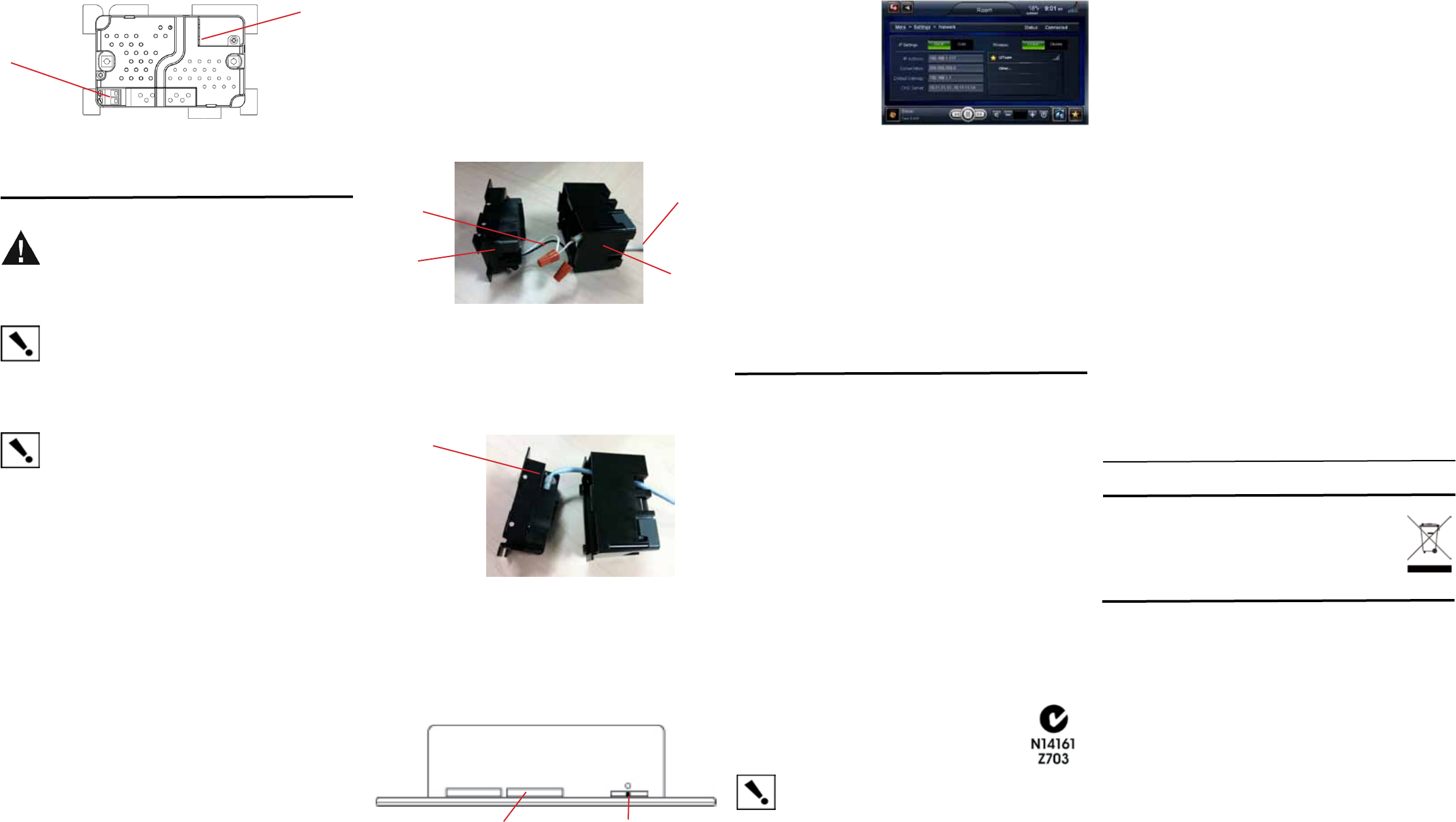
Figure 6. Back View of the InnityEdge 5” or 7” In-Wall Touch Screen
and Power Box
1
2
1.
2.
Wireless Connection:High-voltagepower(H)usesBlackwire;Return(R)uses
Whitewire.
RJ-45 port for Ethernet Connection:Ethernetportavailableforeitherastandard
EthernetsourcethatprovidesnetworkcommunicationonlyORaPoEsourcethat
providespowertothedeviceandnetworkcommunication.