Control4 LCAVMHTC101 System Controller (HTC) User Manual
Control4 System Controller (HTC)
UserManual.wiki
>
Control4
>
LCAVMHTC101 User Manual
Exhibit 8
Navigation menu
Upload a User Manual
Namespaces
Wiki Guide
HTML
PDF
Info
Views
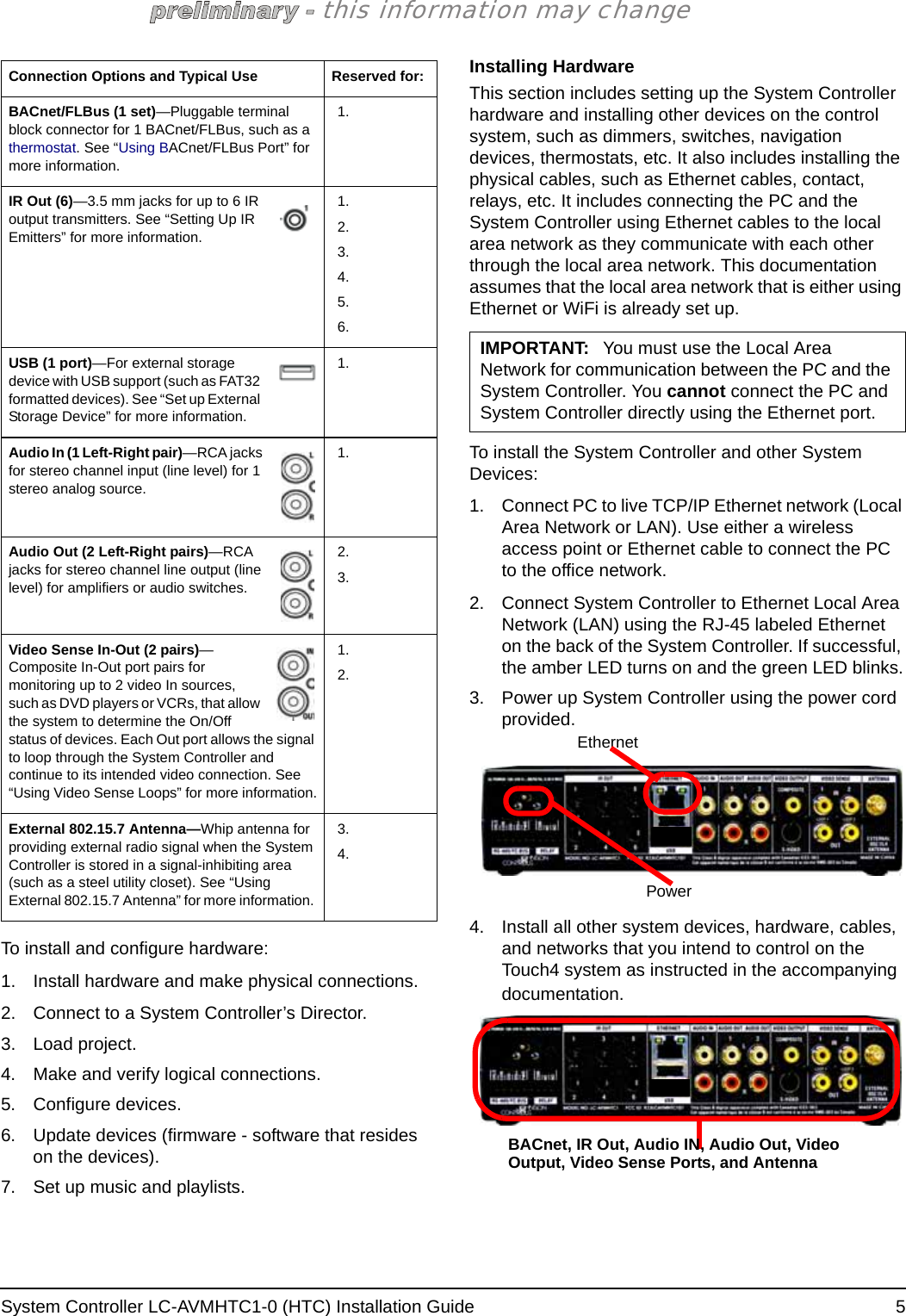
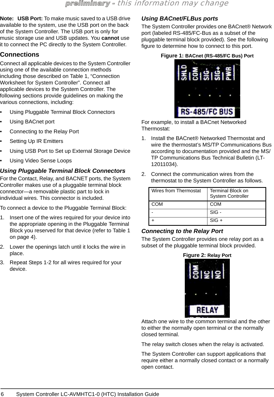
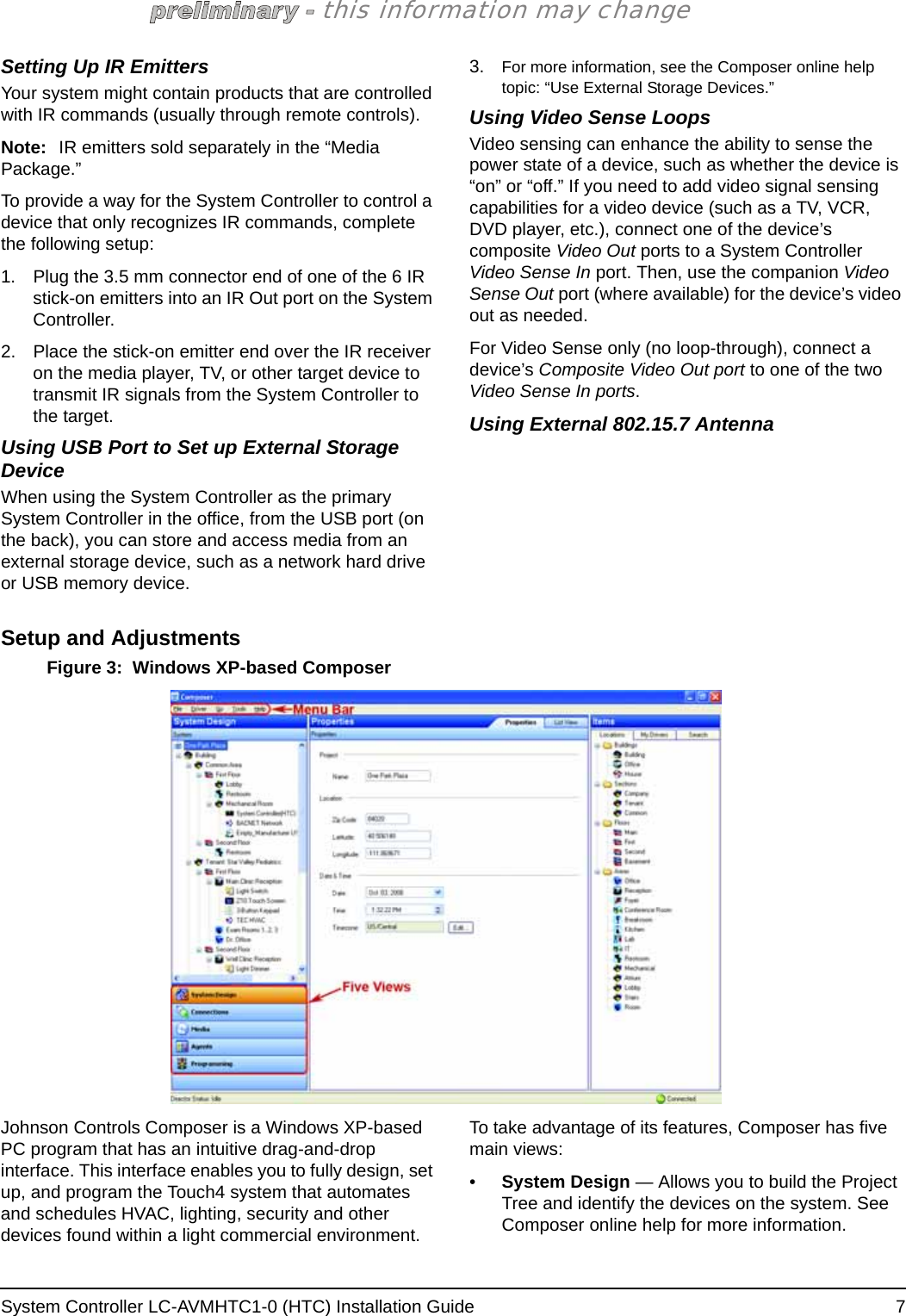
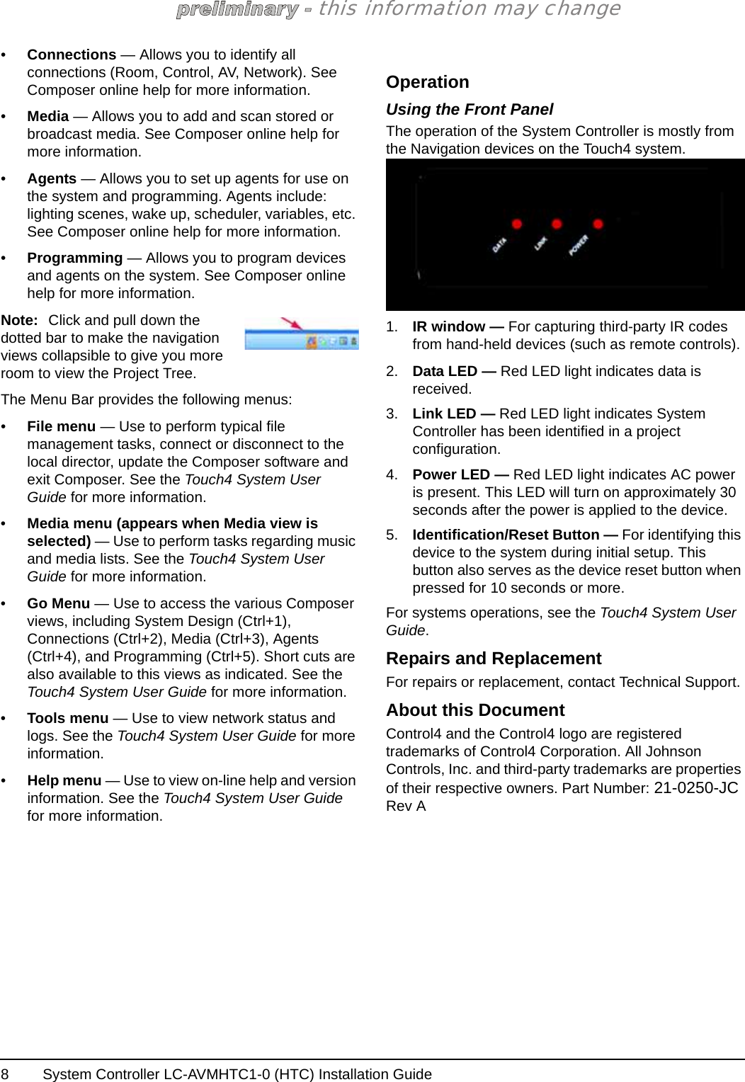
User Manual
Discussion / Help
Navigation