Control4 WAPC11G Carrier Grade Embeddable Access Point User Manual
Pakedge Device and Software Inc. Carrier Grade Embeddable Access Point Users Manual
Control4 >
Contents
- 1. DoC
- 2. Users Manual
Users Manual
Wireless 802.11g AP
User’s Manual
Version 1.0

User’s Guide 1
Federal Communication Commission Interference Statement
This equipment has been tested and found to comply with the limits for a Class B digital device,
pursuant to Part 15 of the FCC Rules. These limits are designed to provide reasonable
protection against harmful interference in a residential installation. This equipment generates,
uses and can radiate radio frequency energy and, if not installed and used in accordance with
the instructions, may cause harmful interference to radio communications. However, there is no
guarantee that interference will not occur in a particular installation. If this equipment does cause
harmful interference to radio or television reception, which can be determined by turning the
equipment off and on, the user is encouraged to try to correct the interference by one of the
following measures:
- Reorient or relocate the receiving antenna.
- Increase the separation between the equipment and receiver.
- Connect the equipment into an outlet on a circuit different from that to which the receiver is
connected.
- Consult the dealer or an experienced radio/TV technician for help.
FCC Caution: To assure continued compliance, any changes or modifications not expressly
approved by the party responsible for compliance could void the user's authority to operate this
equipment.
This device complies with Part 15 of the FCC Rules. Operation is subject to the following two
conditions: (1) This device may not cause harmful interference, and (2) this device must accept
any interference received, including interference that may cause undesired operation.
IMPORTANT NOTE:
FCC Radiation Exposure Statement:
This equipment complies with FCC radiation exposure limits set forth for an uncontrolled
environment. This equipment should be installed and operated with minimum distance 20cm
between the radiator & your body.
This transmitter must not be co-located or operating in conjunction with any other antenna or
transmitter.
Pakedge declares that WAPC11g ( FCC ID: SLY-WAPC11G ) is limited in CH1~CH11 for
2.4GHz by specified firmware controlled in U.S.A.

User’s Guide 2
Copyright Statement
No part of this publication may be reproduced, stored in a retrieval system, or transmitted in any form
or by any means, whether electronic, mechanical, photocopying, recording, or otherwise without the
prior writing of the publisher.
April. 2004

User’s Guide 3
Contents
1. Introduction............................................................................................................... 4
2. Safety Notification .................................................................................................... 5
3. Hardware Installation................................................................................................ 6
4. Web Management Settings ...................................................................................... 7
4.1 Configuration……………………………………………………………………………………………...8
4.2 Local Area Network……………………………………………………………………………………..9
4.3 Wireless…………………………………………………………………………………………………..11
4.4 Security……………………………………………………………………………………………………14
4.5 Location Base Service………………………………………………………………………………..16
4.6 Status Overview………………………………………………………………………………………..17
4.7 Diagnostic………………………………………………………………………………………………..18
4.8 Upgrade Firmware…………………………………………………………………………………….19
4.9 Reboot Access Point…………………………………………………………………………………20
4.10 Restore Factory Defaults………………………………………………………………………….21
4.11 Configuration Profile Download………………………………………………………..22
4.12 Configuration Profile Upload……………………………………………………………23
5. Appendix.................................................................................................................. 24
6. Troubleshooting...................................................................................................... 25

User’s Guide 4
1. Introduction
Thank you for purchasing your AP Wireless 802.11g AP.
This user guide will assist you with the installation procedure.
The package you have received should contain the following items:
AP Wireless 802.11g AP
Quick Installation Guide
Power Supply / Cord
Ethernet Cable
CD
Note: if anything is missing, please contact your vendor

User’s Guide 5
2. Safety Notification
Your Wireless AP should be placed in a safe and secure location. To ensure proper operation, please
keep the unit away from water and other damaging elements. Please read the user manual thoroughly
before you install the device. The device should only be repaired by authorized and qualified
personnel.
Please do not try to open or repair the device by yourself.
Do not place the device in a damp or humid location, i.e. a bathroom.
The device should be placed in a sheltered and non-slip location within a temperature range of
+5 to +40 Celsius degree.
Please do not expose the device to direct sunlight or other heat sources. The housing and
electronic components may be damaged by direct sunlight or heat sources.

User’s Guide 6
3. Hardware Installation
Front Panel
The front panel provides LED’s for device status. Refer to the following table for the meaning of each
feature.
LED STATUS Description
Off No power
Green On 1. Power on 2. Reset to default 3. Firmware upgrade (first 1
minute)
POWER
Green
Blink 1. System up 2. Power on 3. Firmware upgrade
Off No Ethernet link detected
Green On 10/100Mbps Fast Ethernet link detected.
LINK
Green
Blink Indicates data traffic on the 10/100 Mbps LAN
ACT Green
Blink Indicates the device is linking or active data through wireless
links
Side Panel
The side panel features 1 LAN ports and Reset button. Refer to the following table for the meaning of
each feature.
Power (DC 5v)
Used to connect to the power outlet. Only use the power
adapter provided with the device. Use of an unauthorized
power adapter may cause damage to your device and
violate your warranty.
Reset Press the Reset Button for approximate ten seconds, all
configurations will set to factory default settings.
LAN The RJ-45 Ethernet port used to connect your PC, hub,
switch or Ethernet network.
AP Default Settings
The default settings are shown following.
User
Password
AP IP Address 192.168.1.250
AP Subnet Mask 255.255.255.0
RF ESSID ap11g
11g RF Channel 6
Mode 11b+g
Encryption Disabled
User’s Guide 7
4. Web Management Settings
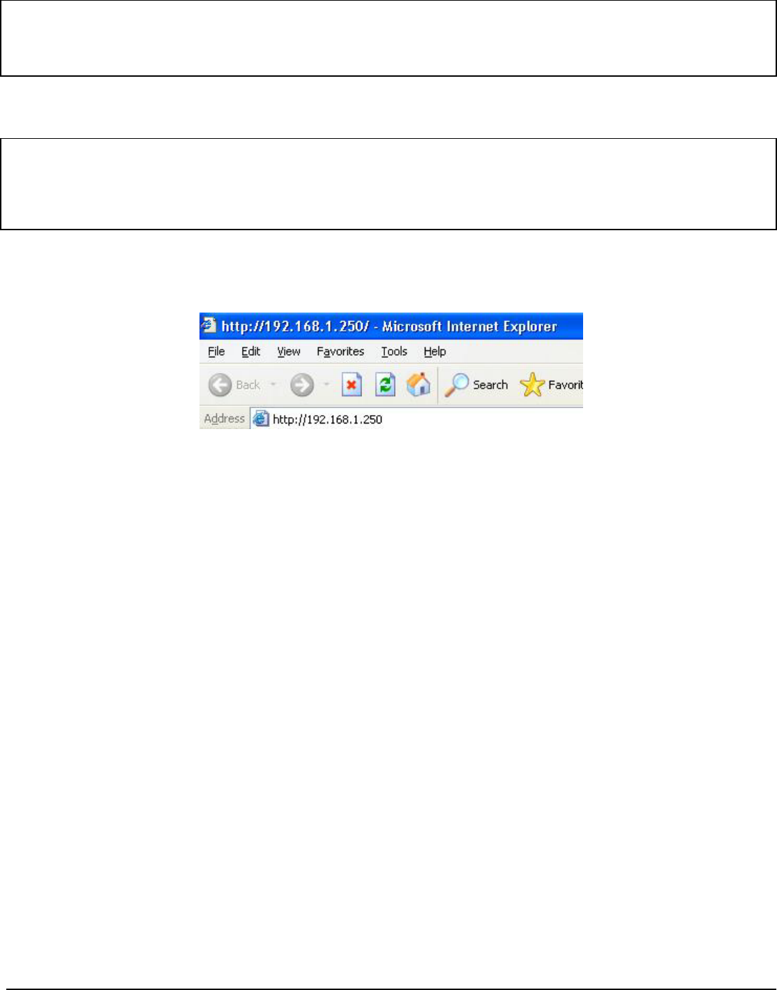
START UP & LOGIN
In order to configure the Wireless 11g AP, you must use your web browser and manually input
http://192.168.1.250 into the Address box and press Enter on explorer. The Main Page will appear.
Once you have logged-in this unit, it is a good idea to enable the password protection to ensure a
secure protection to the Wireless 11g AP. The Security Settings section described later in this manual
describes how to change the password.
Once you have input the correct password and logged-in, the screen will change to the Setup page
screen.
TURN ON POWER SUPPLY
Quick power cycle can caused system corruption. When power on, be careful not to shut down in
about 5 seconds, because data is writing to the flash.
Before Starting
The default IP address setting for the unit is a class C IP address (192.168.1.250/ 255.255.255.0).
Please make sure that the current workstation is following the class C IP address range, from
192.168.1.1 to 192.168.1.254 if
y
ou would like to do an
y
confi
g
uration b
y
this workstation.
User’s Guide 8
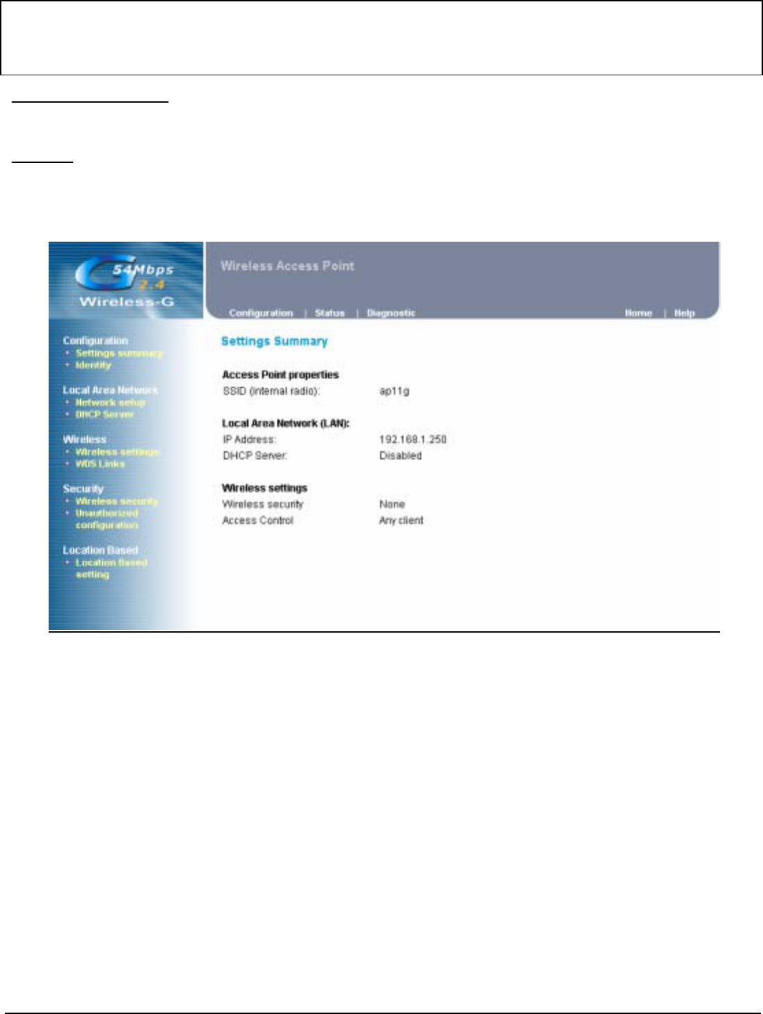
4.1 Configuration
Settings Summary
This section contains the AP's basic settings information.
Identity
This section contains the AP's current firmware version. Also It can allow user to define the identity
information for this unit if there are many same type units locate at one network.
MAKE CORRECT NETWORK SETTINGS OF YOUR COMPUTER
To change the configuration, use Internet Explorer (IE) or Netscape Communicator to connect the
WEB management 192.168.1.250.
User’s Guide 9
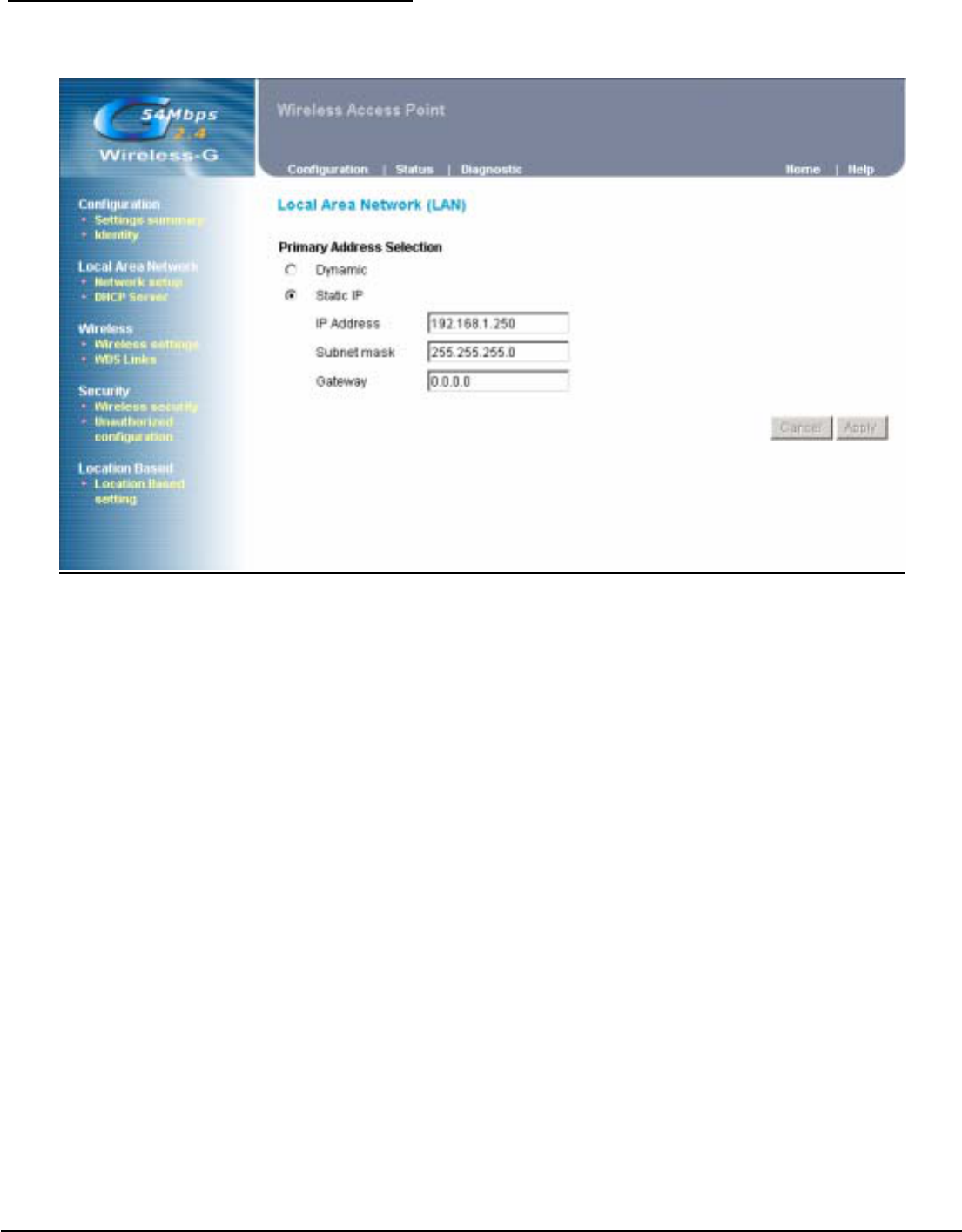
4.2 Local Area Network
Network setup ( Local Area Network )
This is the AP's IP Address and Subnet Mask as seen on the internal LAN. The default value is
192.168.1.250 for IP Address and 255.255.255.0 for Subnet Mask.
User’s Guide 10
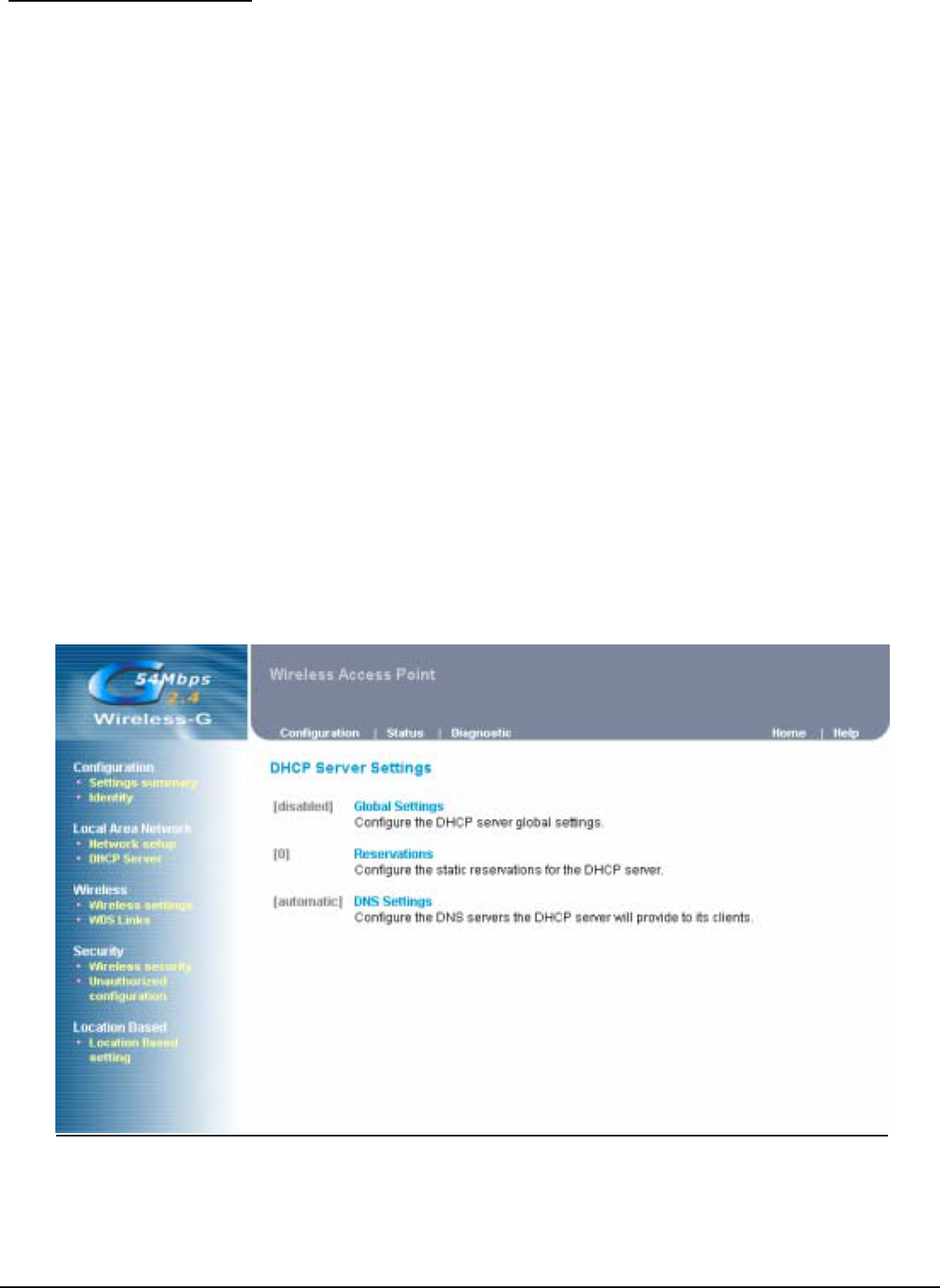
DHCP Server Settings
The DHCP Server section allows you to configure the settings for the AP's Dynamic Host
Configuration Protocol (DHCP) server function. The AP can be used as a DHCP server for your
network. A DHCP server automatically assigns an IP address to each computer on your network. If
you choose to enable the AP's DHCP server option, you must configure your entire network PCs to
connect to a DHCP server, the AP.
If you disable the AP's DHCP server function, you must configure the IP Address, Subnet Mask, and
DNS for each network computer (note that each IP Address must be unique).
Global Settings: Select the Enable option to enable the AP's DHCP server option.
If you already have a DHCP server on your network or you do not want a DHCP
server, then select Disable from the options.
If you enable the DHCP server function, you have to enter a numerical value for the
DHCP server starting and ending addresses. Then the DHCP server will follow this
range to assign IP address for each DHCP clients.
If your DHCP clients must route to other network or with internet service, then the
Gateway IP address will be necessary.
Reservations : If some of network hosts would like to be assigned one fixed IP address by this
DHCP server, please enable the Reservations and add reservation record with MAC
address and preferred IP address.
DNS settings : The Domain Name System (DNS) is how the Internet translates domain or website
names into Internet addresses or URLs. Your ISP will provide you with at least one
DNS Server IP Address. If you wish to utilize another DNS, please add static DNS
IP Address to DHCP server.

User’s Guide 11
4.3 Wireless
Wireless settings
This page contains settings for the identification and radio channel use of the Access Point:
Regulatory Domain: this is the organization that certifies the Access Point for use in your country. It
determines which radio channels can be used to transmit and receive signals.
IAPP : IAPP can be defined to allow the new AP to obtain the authentication information
from the old AP and send a new EAPOL-Key message to the STA with a new
set of WEP keys. An IAPP should also transfer to the new AP enough of the
RADIUS server account information for the new AP to continue the same
account records rather than start a new account record.
SSID : only Access Points and clients that share this SSID are able to communicate with
each other. Your networking client allows you to choose to which network you
connect. The network names you see there are SSIDs.
Band : select the policy for internal radio. There are 3 types of band setting, the default
mode is Mixed.
Radio Channel : select the appropriate channel from the list provided to correspond with your
network settings. You shall assign a different channel for each AP to avoid
signal interference.
PRISM Nitro : this mode can improve performance slightly but will break downward
compatibility with some older products.
Current Tx Power Level: this setting allows to adjust output power of this unit. Set value to “1” will
tune the power to Maximum level.
Broadcast SSID : this setting is related with SSID for whether it can be broadcasted by wireless
or not.
Enable L2 Isolation: enable this setting will reject clients to communicate between themselves by this
AP.
Transmission Rates: The rate of data transmission should be set depending on the speed of your
wireless network. You can select from a range of transmission speeds, or you
can select AUTO to have the AP automatically use the fastest possible data
rate.
Preamble Type : select the head length of the packet. There are 2 types can be supported, long
and short.

User’s Guide 12
User’s Guide 13
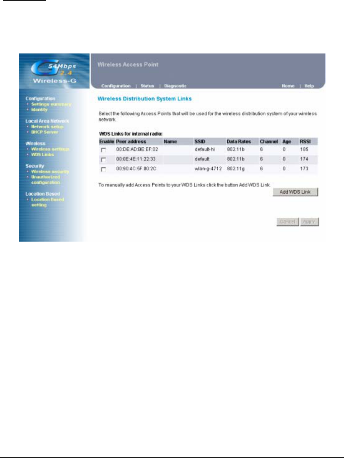
WDS Links
This mode allows the AP to keep the AP function role and at the same time performing a
communication with other 802.11g AP to establish and extend your Wireless Network coverage.
Please select the checkbox to enable AP on the WDS list to perform WDS application or enter the
Remote Access Point’s MAC address to enable this feature.
User’s Guide 14
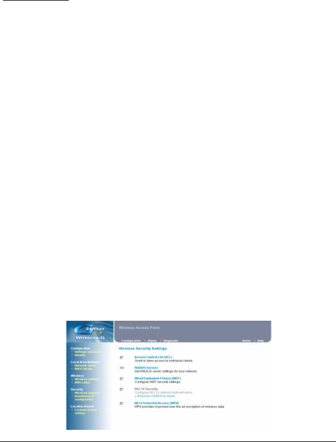
4.4 Security
Wireless Security
The Wireless Security Setting separates 5 items setting. They are included ACL, RADIUS Server,
WEP, 802.1X and WPA.
Access Control List : This function will allow administrator to have access control by enter MAC
address of client stations.
RADIUS Servers : With this option you use a RADIUS server to handle access control.
RADIUS (“Remote Authentication Dial In User Service” is a standard for user authentication. The
RADIUS server contains a database with users and their access rights. When a user wants to use the
Access Point, the Access Point contacts the RADIUS server to see if this is permitted.
To add a RADIUS server:
1. Click Add to add a RADIUS server.
2. In the window that appears, enter the following data:
- IP Address: the IP address of the RADIUS server.
- UDP Port: the UDP port number of the RADIUS server.
- Secret: the password for access to the RADIUS server.
3. Click OK. The server is now added to the list.
You can add more than one RADIUS server. The first server in the list will be used by default, the
second will be used if the first is not available, etc.
To delete a RADIUS server from the list:
1. Click Delete.
2. Select the RADIUS server that you want to remove from the list.
3. Click OK. The list is updated.
Wired Equivalent Privacy (WEP) : select the check box will enable WEP function. WEP security
supports 2 types encrypted format, one is Hexadecimal and the other is ASCII format.
802.1X Security : select the check box will enable 802.1X security. Please select one suitable key
size and rekeying setting.
Wi-Fi Protected Access (WPA) : The WPA security pre-shared key supports TKIP algorithm. TKIP
stands for Temporal Key Integrity Protocol. TKIP utilizes a stronger encryption method and
incorporates Message Integrity Code (MIC) to provide protection against hackers. To use WPA Pre-
Shared Key, enter a password in the WPA Shared Key field between 8 and 63 characters long. You
may also enter a Group Key renewal interval time.
User’s Guide 15
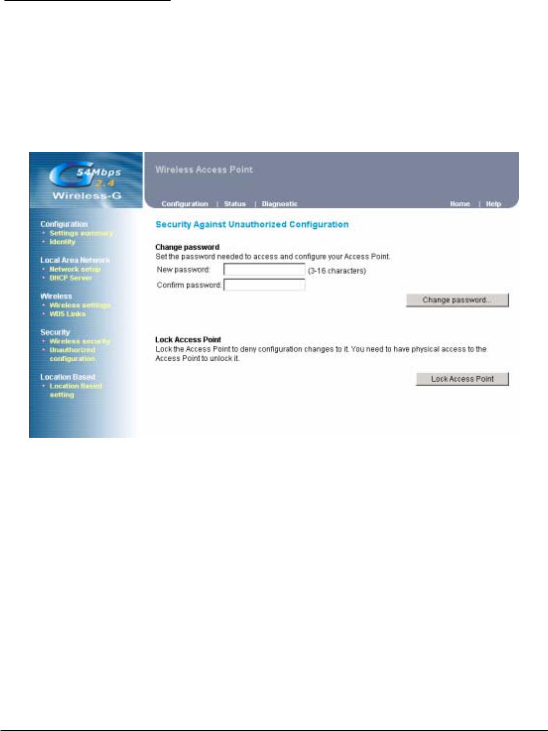
Unauthorized configuration
Changing the password for the AP is as easy as typing the password into the New Password field.
Then, type it again into the Confirm password to confirm.
There is no default password when you first open the configuration pages, after you have configured
these settings, you should set a new password for the AP (using the Password screen). This will
increase security, protecting the AP from unauthorized changes.
Also you can lock this AP to deny any configuration changes. Once you lock this AP, only by hardware
reset can unlock this device.
User’s Guide 16
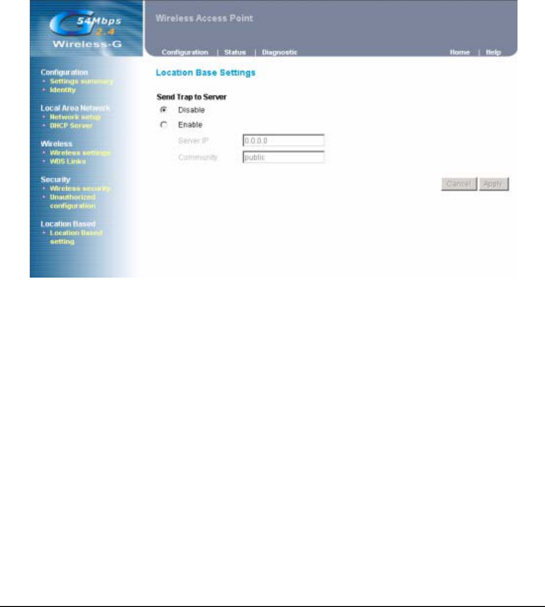
4.5 Location Base Service
Every time a client associated or disassociated to the Access Point, the AP can send a trap to the
Location base Server.
If you enable Location base service, please enter the IP address of the Location base server who will
process these traps.
Also the Community String is necessary for Location base server authentication before accept these
traps.
.
User’s Guide 17
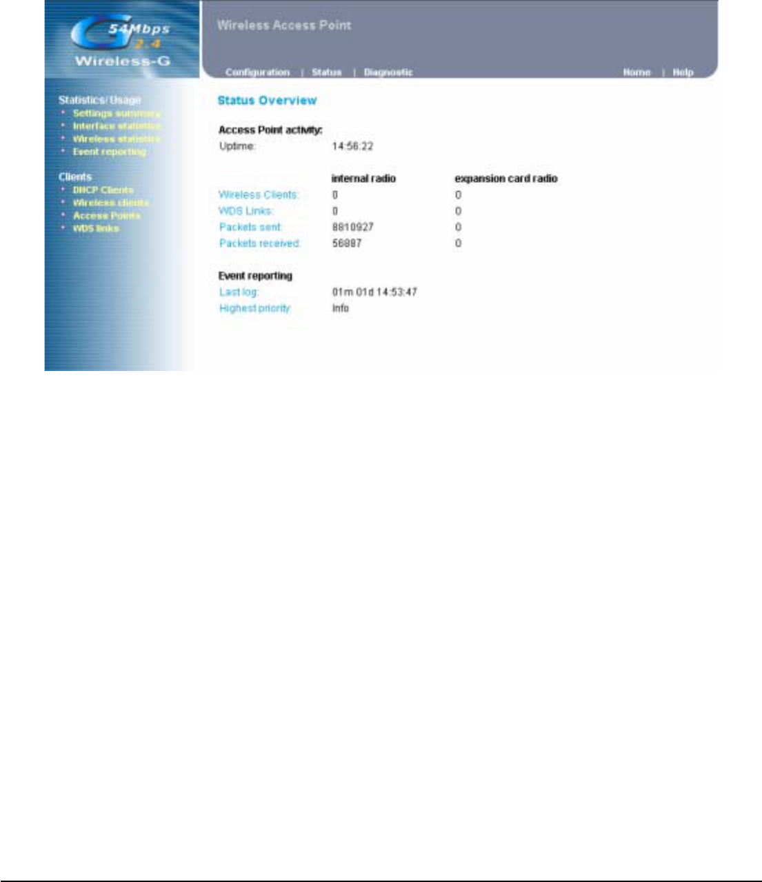
4.6 Status Overview
In this section, we provide a series of statistics about this AP. User can check each status via this
page. For example, if you would like to check how many clients already associated on this AP, you
may click the link on left site “ Wireless clients “ for detail. For other detail information, please tip other
links for reference.
User’s Guide 18
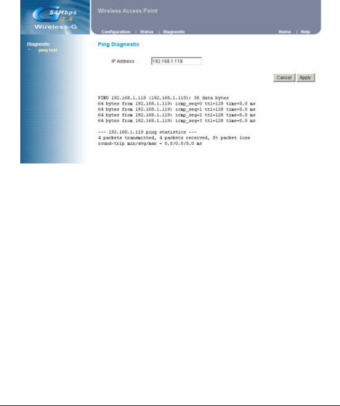
4.7 Diagnostic
This function provides one simple diagnostic method for check if the LAN connection that want to
connect is exist or not.
Please fill in one IP address with same subnet to AP then click apply. Normally it will take several
seconds for reply like below screen.

User’s Guide 19
4.8 Upgrade Firmware
Click the Upgrade button to load new firmware onto the AP. If the AP is not experiencing difficulties,
then there is no need to download a more recent firmware version, unless that version has a new
feature that you want to use.
User’s Guide 20
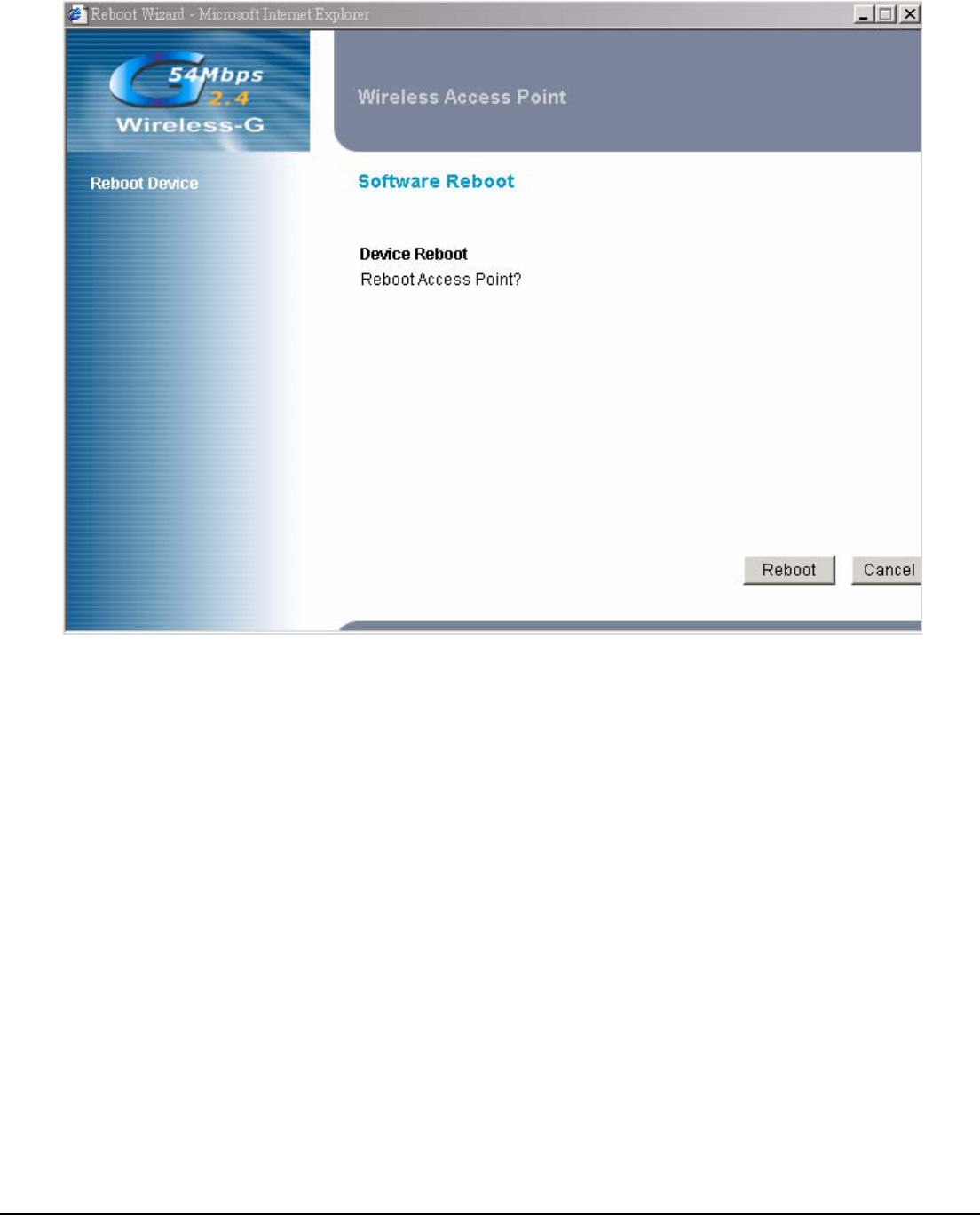
4.9 Reboot Access Point
This function provides AP performing an initial action by web management. Same result could be done
by power off/on this unit.

User’s Guide 21
4.10 Restore Factory Defaults
Click the Reset button to reset all configuration settings to factory default values.
Note: Any settings you have saved will be lost when the default settings are restored.
User’s Guide 22
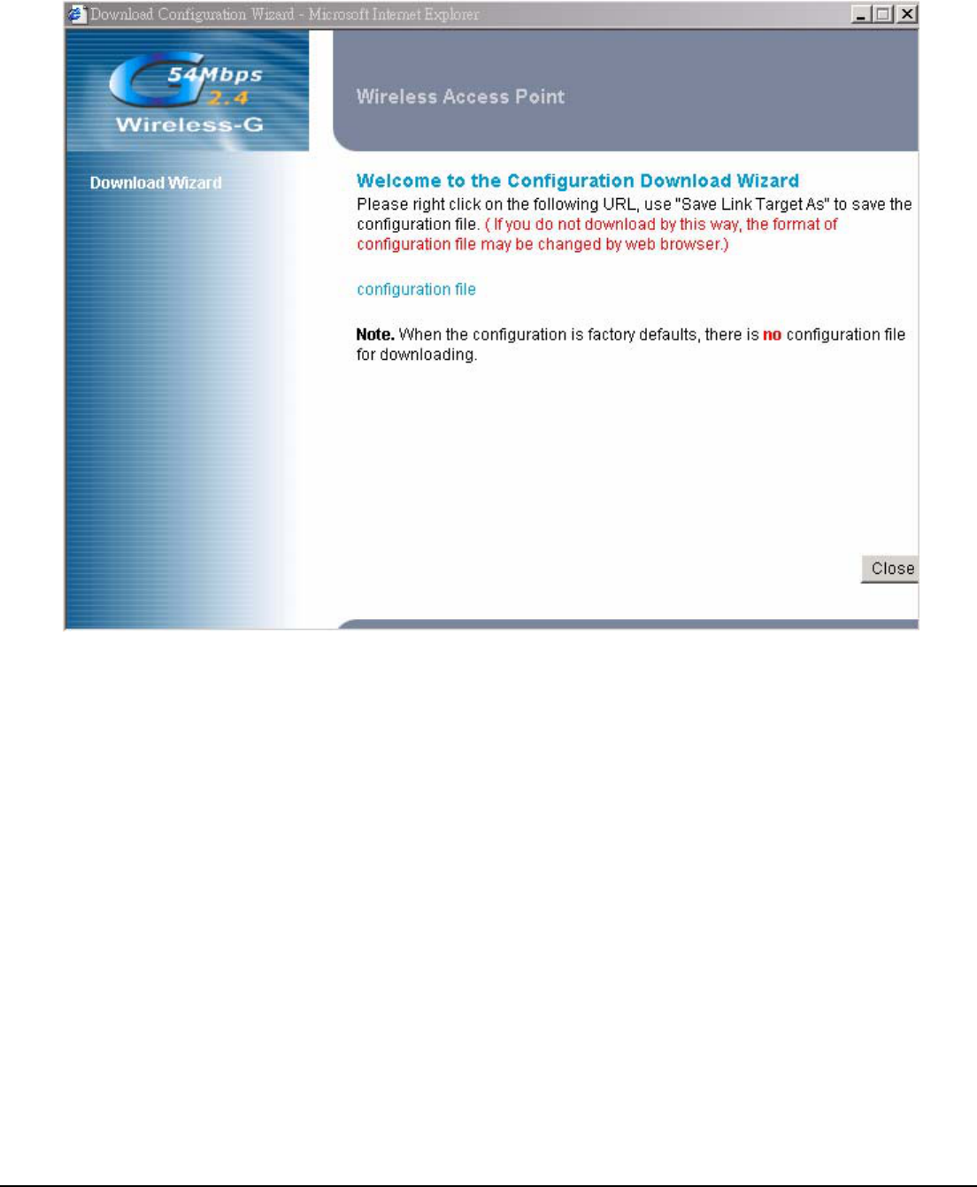
4.11 Configuration Profile Download
This function provides AP configuration download, user can save current AP settings in one profile for
later restored usage. Using this way can save more time for reconfig this device again if it has been
reset factory default.
User’s Guide 23
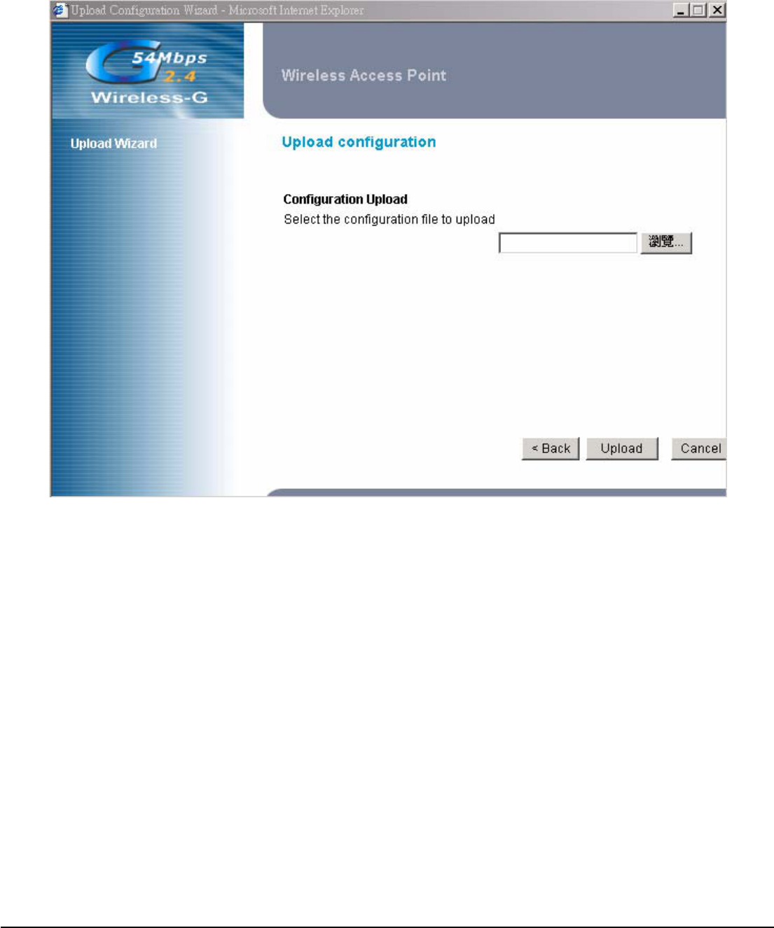
4.12 Configuration Profile Upload
This function provides AP configuration upload, user can use profile that saved before for restore this
unit.
User’s Guide 24
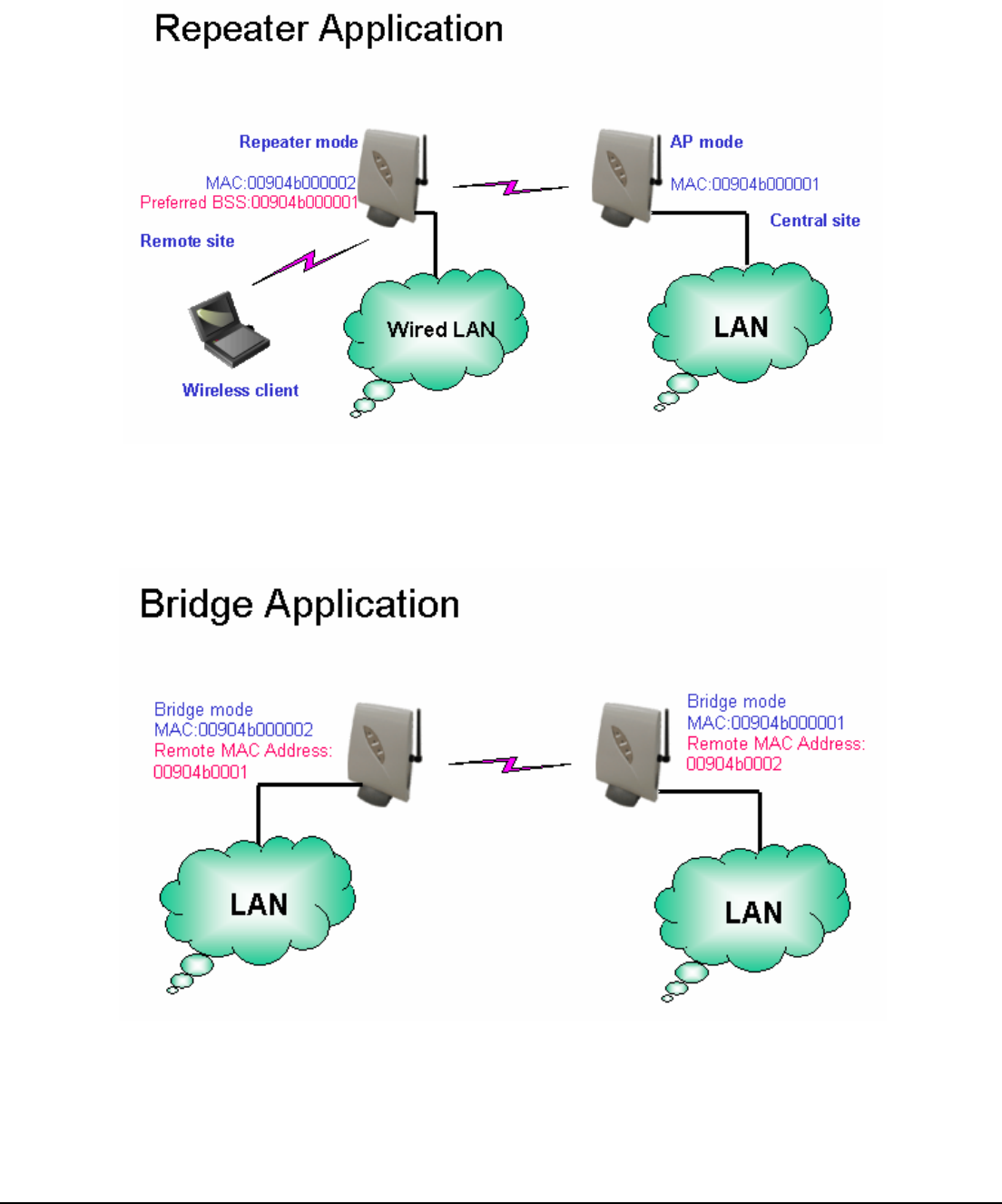
5. Appendix
WDS Links Application: Enable WDS function can perform following 2 applications
WDS (AP Repeater): This mode allows the AP to keep the AP function role and at the same time
performing a communication with other 802.11g AP to establish and extend your Wireless Network
cover. Please enter the Remote Access Point’s MAC address to enable this feature.
Wireless Bridge: This mode allows the connection of one or more remote LANs with a central LAN.

User’s Guide 25
6. Troubleshooting
Basic Functions
My Wireless AP will not turn on. No LED’s light up.
Cause:
The power is not connected.
Resolution:
Connect the power adapter to your AP and plug it into the power outlet.
Note: Only use the power adapter provided with your AP. Using any other adapter may damage your
AP.
LAN Connection Problems I can’t access my AP.
Cause:
The unit is not powered on.
There is not a network connection.
The computer you are using does not have a compatible IP Address.
Resolution:
Make sure your AP is powered on.
Make sure that your computer has a compatible IP Address. Be sure that the IP Address used on
your computer is set to the same subnet as the AP. For example, if the AP is set to 192.168.1.250,
change the IP address of your computer to 192.168.1.15 or another unique IP Address that
corresponds to the 192.168.1.X subnet.
Use the Reset button located on the rear of the AP to revert to the default
settings.
I can’t connect to other computers on my LAN.
Cause:
The IP Addresses of the computers are not set correctly.
Network cables are not connected properly.
Windows network settings are not set correctly.
Resolution:
Make sure that each computer has a unique IP Address. And the IP must be in the same subnet as
the AP.
Make sure that the Link LED is on. If it is not, try a different network cable.
Check each computer for correct network settings.

User’s Guide 26
Wireless Troubleshooting
I can’t access the Wireless AP from a wireless network card
Cause:
Out of range.
IP Address is not set correctly.
Resolution:
Make sure that the Mode, SSID, Channel and encryption settings are set the same on each
wireless adapter.
Make sure that your computer is within range and free from any strong electrical devices that may
cause interference.
Check your IP Address to make sure that it is compatible with the Wireless AP.