NCD Essential Quick Start Guide For Fusion Series Controllers Digital IO
2014-10-27
: Controlanything Fusion Digital Io Quick Start Guide Fusion_Digital_IO_Quick_Start_Guide QSG
Open the PDF directly: View PDF ![]() .
.
Page Count: 10

NATIONAL CONTROL DEVICES
Fusion Digital Input/Output Quick Start Guide

N A T I O N A L C O N T R O L D E V I C E S
Fusion Digital I/O Quick Start Guide
National Control Devices, LLC
PO Box 455
Osceola, MO 64776
Phone 417.646.5644 • Fax (866) 562-0406
IORelay.com
© Copyright 2013
All Rights Reserved.
Notice: Portions of this manual require internet access.

Table of Contents
Fusion Digital I/O Quick Start Guide ......................................... 1
Port Direction .................................................................................. 1
Port 1 Commands (Decimal Format)............................................... 4
Port 2 Commands (Decimal Format)............................................... 4
Port 1 Commands (Hexadecimal Format) ....................................... 4
Port 2 Commands (Hexadecimal Format) ....................................... 4
EEPROM Memory........................................................................... 5
EEPROM Memory Locations .......................................................... 5
Technical Support .................................................................... 6
Contact Information ......................................................................... 7
Notice: ....................................................................................................... 7

F U S I O N S E R I E S
1
Fusion Digital I/O Quick Start Guide
The Fusion® Series is our fourth generation relay controller offering
the ultimate relay control solution . . . without exception.
Fusion Series controllers support up to two ports of 8-bit digital input/output,
allowing users to read and control 5V digital signals using only a few simple
commands. When used for digital input applications, Fusion controllers are
capable of reading inputs such as switches, magnet sensors, and other contact
closure devices. Digital output makes it easy to control LEDs and some logic
circuits at very high speed.
Port Direction
The first step in using the Digital I/O features of Fusion series controllers is a
complete understanding of port direction. Each 8-bit port may be configured to
read inputs, write outputs, or both in combination. When the port is set to all
inputs, eight switches can be read as long as the input does not exceed 0 to 5 Volts
DC. When the port is set to all outputs, eight LEDs can be controlled by software,
allowing you to turn each LED on or off in any combination. It is easy to mix
inputs and outputs, allowing users to read four switches and control four LEDs.
Each I/O line on the Fusion controller may be configured to input or output, but
you must set the status of all eight I/O lines at one time using a single command.
Here’s an example:
236 2 255 Set I/O Lines 1 to 8 to Input Rx: 255
236 2 0 Set I/O Lines 1 to 8 to Output Rx: 0
236 2 15 Set I/O Lines 1-4 to Input, 5-8 to Output Rx: 15
The third byte in the Port Direction command is used to set the digital input or
output state of all eight data lines on the I/O port. Here’s how you decide what
this value should be:
Each I/O bit has a value associated, as shown below:
IO 8 IO 7 IO 6 IO 5 IO 4 IO 3 IO 2 IO 1
Bit 7 Bit 6 Bit 5 Bit 4 Bit 3 Bit 2 Bit 1 Bit 0
Chapter
1

F U S I O N S E R I E S
2
128 64 32 16 8 4 2 1
Each of these 8 bits may be On or Off:
1 = On = Input
0 = Off = Output
If we turn on every other bit, we get this:
IO 8 IO 7 IO 6 IO 5 IO 4 IO 3 IO 2 IO 1
Bit 7 Bit 6 Bit 5 Bit 4 Bit 3 Bit 2 Bit 1 Bit 0
In Out In Out In Out In Out
1 0 1 0 1 0 1 0
128 0 32 0 8 0 2 0
Bits 8, 6, 4, and 2 will be turned on, setting them to input; the other bits will
remain off, setting them to output.
Now we add the bits together:
128 + 32 + 8 + 2 = 170
Now we send the command:
236 2 170 Sets I/O Line 0 to Output
Sets I/O Line 1 to Input
Sets I/O Line 2 to Output
Sets I/O Line 3 to Input
Sets I/O Line 4 to Output
Sets I/O Line 5 to Input
Sets I/O Line 6 to Output
Sets I/O Line 7 to Input
Controller responds with: Rx: 170
F U S I O N S E R I E S
3
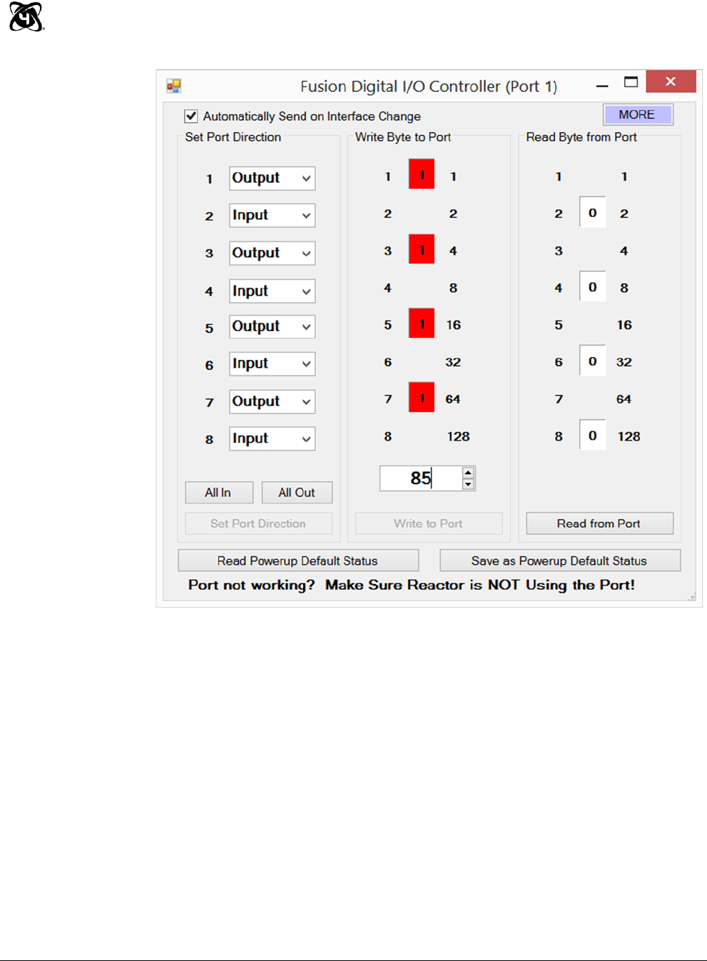
In the screen shot above, the 8-bit I/O Port was configured for input and
output. I/O lines 1, 3, 5, 7 are outputs while I/O lines 2, 4, 6, 8 are set to
inputs. The value 85 was written to the port, turning on I/O lines 1, 3, 5,
and 7 (these lines can be used to drive LEDs). Inputs 2, 4, 6, and 8 can
be used to read switches, and will light RED if the input is high and you
click the “Read from Port” button.

F U S I O N S E R I E S
4
Port 1 Commands (Decimal Format)
Value can be any number from 0 to 255, and follows the 8-bit binary standard.
236 0 <Value> Write Output values to output bits of I/O port Rx: <OutputValue>
236 1 <Value> Read Input value from input bits of I/O Port Rx: <Input Value>
236 2 <Value> Set Port Direction Command Rx: <Direction Value>
Port 2 Commands (Decimal Format)
Value can be any number from 0 to 255, and follows the 8-bit binary standard.
236 0 <Value> 2 Write Output values to output bits of I/O port Rx: <Output Value>
236 1 2 Read Input value from input bits of I/O Port Rx: <Input Value>
236 2 <Value> 2 Set Port Direction Command Rx: <Direction Value>
Port 1 Commands (Hexadecimal Format)
Value can be any number from 0 to 255, and follows the 8-bit binary standard.
0xEC 0x00 <Value> Write Output values to output bits of I/O port Rx: <Output Value>
0xEC 0x01 Read Input value from input bits of I/O Port Rx: <Input Value>
0xEC 0x02 <Value> Set Port Direction Command Rx: <Direction Value>
Port 2 Commands (Hexadecimal Format)
Value can be any number from 0 to 255, and follows the 8-bit binary standard.
0xEC 0x00 <Value> 0x02 Write Output values to output bits of I/O port Rx: <Output Value>
0xEC 0x01 0x02 Read Input value from input bits of I/O Port Rx: <Input Value>
0xEC 0x02 <Value> 0x02 Set Port Direction Command Rx: <Direction Value>

F U S I O N S E R I E S
5
EEPROM Memory
EEPROM Memory stores the state of each port when power
is first applied to the controller. Please review the Fusion
EEPROM Quick Start Guide for complete details.
EEPROM Memory Locations
280 Stores the Direction of Port 1
281 Stores the On/Off status of each bit of Port 1
282 Stores the Direction of Port 2
283 Stores the On/Off status of each bit of Port 2
F U S I O N S E R I E S
6
Technical Support
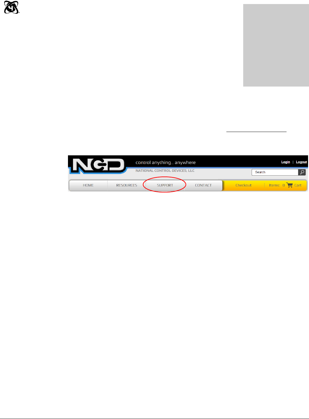
echnical support is available through our website, controlanything.com.
Support is the way we connect NCD engineers to our customers.
Click on the Support tab at the top of any page on our website to be
taken to the Forum page. Here you can publicly post or review problems
that customers have had, and learn about our recommended solutions.
Our engineers monitor questions and respond continually throughout the day.
Before requesting telephone technical support, we ask that customers please try to
resolve their problems through Support first. However, for persistent problems,
NCD technical support engineers will schedule a phone consultation.
Chapter
2
T

F U S I O N S E R I E S
7
Contact Information
National Control Devices, LLC
PO Box 455
Osceola, MO 64776
417-646-5644 phone
866-562-0406 fax
Open 9 a.m. - 4 p.m. CST
Like “National Control Devices” on Facebook, and follow us on Twitter
@ControlAnything.
All orders must be placed online at our website, www.controlanything.com
Notice:
The only authorized resellers of NCD products are
www.controlanything.com
www.relaycontrollers.com
www.relaypros.com
All other websites are not authorized dealers; we have noticed some retailers
offering our products fraudulently.
Copyright © 2013
National Control Devices
All Rights Reserved.
