Controlanything Proxr PROXR_V2 User Manual Pro XR
2012-01-17
User Manual: Controlanything Proxr ProXR manuals
Open the PDF directly: View PDF ![]() .
.
Page Count: 44
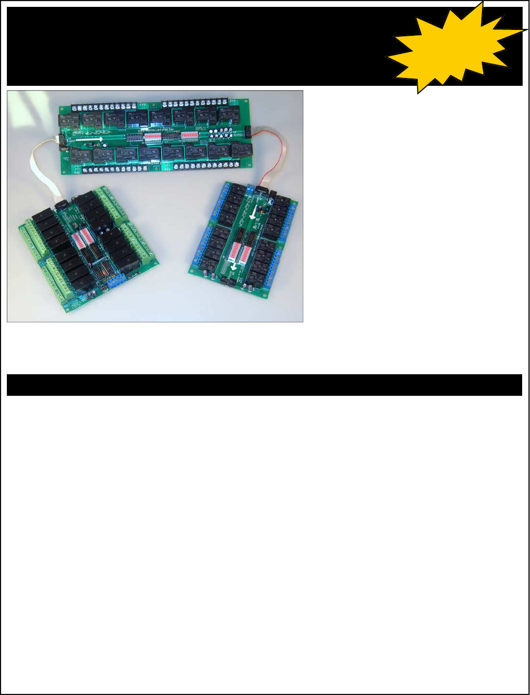
ProXR Series
RS-232 E3C Networkable Relay Controllers
Control 256 Devices from a Single Serial Port
Watchdog / Server Reboot / Keep Alive Timing Functions
Supports Duration Timing Commands (turn a light on for 8 hours)
Control 256 Relays (32 Relay Banks) From One Controller
User-Selectable Communication Rates up to 115.2K Baud
Change Parameters in Configuration Mode ONLY to Prevent Accidental Changes
E3C Compliant Command Set
Diode Clamped Relay Driver Stage
Relay Status LEDs
Device Enabled/Power LED
Data Receive LED
12 Volt DC Operation
User-Programmable Startup Status
Simultaneously Set the Status All Relays
Ask the Status of Individual or All Relays
Protected E3C Device Numbering
O.C. RS-232 Communication for Networking Multiple Devices
Powerful ASCII Character Code Based Command Set
Compatible with ANY Computer or Microcontroller
NCD Relay Controllers: Feature Comparison Original R4x/R8x
Relay Controllers
R4x/R8x Pro Relay
Controllers
ProXR Series
Controllers
Optoisolation on RS-232 Data Inputs Yes Yes No, Full Speed RS232 Only
R4x Pro Form Factor Compatible with Original R4x Design - R45 Pro is Smaller New Form Factor, Many
New Varieties
R8x Pro Form Factor Compatible with Original R8x Design - Yes New Form Factor, Many
New Varieties
XR Expansion Ports (Allow you to add additional relay banks at a later time) No No Yes
Protected Memory Storage (Must set controller to Configuration Mode to Define Device Number) No No Yes
Set Status of Individual Relays Yes Yes Yes
Set Status of Multiple Relays Simultaneously No Yes Yes
Set Status of Multiple Banks of Relays Simultaneously No No Yes
Read Status of Individual Relays No Yes Yes
Read Status of Multiple Relays Simultaneously Yes Yes Yes
16 Device Network Compliance Yes Yes, Emulation Mode No, E3C Compliance Only
E3C 256 Device Network Compliance No Yes Yes
Programmable Relay Timer No Yes Yes, 16 Background
Programmable Device Number Jumper Configured Software Configured Software Configured
(protected memory)
Programmable Power-up Relay Status No Yes Yes
Programmable Relay Status Memory Banks No Yes No
Multi-Parameter Command Structure No Yes Yes
Relay Select/Deselect Command Set No Yes No
Extended Relay Control Command Set No Yes No
Integrated User-Programmable Memory No Yes Yes
20 MHz CPU Operation No Yes Yes
Maximum Communication Baud Rate 19,200 38,400 115,200
5-Year Repair
or Replace
Warranty!!!
With 16 Background timers and XR Expansion Ports, the
ProXR Series Relay Controllers offer more features than any
other relay controller we have ever produced.
NCD ProXR Series Controllers are our latest generation of relay
controllers. Developed in 2005 and released into mass production for
2006, these controllers place a heavy emphasis on communication
speed, relay bank expansion, and relay timing control.
The ProXR Series Controllers include an XR Expansion port, allowing
you to add additional banks of relays (any kind of relays you need),
directly to the main controller. With a few minor programming modifi-
cations, you will be controlling the new relay banks in seconds. Up to
256 relays (32 Banks of 8 Relays) are Supported with version 17
firmware. You can now control individual relays, relay banks, or all
relays at one time.
The ProXR Series Controllers also offer full-speed RS-232 communi-
cations, up to 115.2K Baud, and are E3C Network Compliant up to
38.4K Baud.
Also new for the 2006 release year is the addition of 16 background
timers, ideal for watchdog, keep alive, server reboot, and duration
timing applications.

This manual covers all NCD products with ProXR in the Part Number as well as other part numbers that may reference this document.
Device Variations
5-Year Repair or
Replace Warranty
Warranty
NCD Warrants its products against defects in materials and
workmanship for a period of 5 years. If you discover a defect,
NCD will, at its option, repair, replace, or refund the purchase
price. Simply return the product with a description of the prob-
lem and a copy of your invoice (if you do not have your invoice,
please include your name and telephone number). We will
return your product, or its replacement, using UPS ground ship-
ping service.
This warranty does not apply if the product has been modified
or damaged by accident, abuse, or misuse.
30-Day Money-Back Guarantee
If, within 30 days of having received your product, you find that
it does not suit your needs, you may return it for a refund. NCD
will refund the purchase price of the product, excluding ship-
ping/handling costs. This guarantee does not apply if the prod-
uct has been altered or damaged.
Copyrights and Trademarks
Copyright 2007, NCD, inc. All rights reserved. Other brand
and product names are trademarks of registered trademarks of
their respective holders.
Disclaimer of Liability
NCD is not responsible for special, incidental, or consequential
damages resulting from any breach of warranty, or under any
legal theory, including lost profits, downtime, goodwill, damage
to or replacement of equipment or property, and any costs or
recovering, reprogramming, or reproducing any data stored in
or used with NCD products.
Technical Assistance
Technical questions can be e-mailed to Ryan Sheldon. For our
latest email address, please visit the Contact section of our
web site. Technical questions submitted via e-mail are an-
swered up to 20 times daily. Technical support is also avail-
able by calling (417) 646-5644.
NCD Contact Information
Mailing Address:
National Control Devices
P.O. Box 455
Osceola, MO 64776
Telephone:
(417) 646-5644
FAX:
(866) 562-0406
Internet:
www.controlanything.com
www.controleverything.com
The ProXR Family:
R165PROXR 16-Channel 5A SPDT RS-232 Relay Controller with XR Expansion Port
R1610PROXR 16-Channel 10A SPDT RS-232 Relay Controller with XR Expansion Port
R81DPDTOC8LP 8-Channel 1A DPDT Relay + 8-Channel 150ma O.C. Output RS-232 Relay Controller
R83DPDTOC8LP 8-Channel 3A DPDT Relay + 8-Channel 150ma O.C. Output RS-232 Relay Controller
R85DPDTOC8LP 8-Channel 5A DPDT Relay + 8-Channel 150ma O.C. Output RS-232 Relay Controller
R81DPDTR85PROXR 8-Channel 1A DPDT Relay + 8-Channel 5A SPDT RS-232 Relay Controller
R81DPDTR810PROXR 8-Channel 1A DPDT Relay + 8-Channel 10A SPDT RS-232 Relay Controller
R83DPDTR85PROXR 8-Channel 3A DPDT Relay + 8-Channel 5A SPDT RS-232 Relay Controller
R83DPDTR810PROXR 8-Channel 3A DPDT Relay + 8-Channel 10A SPDT RS-232 Relay Controller
R85DPDTR85PROXR 8-Channel 5A DPDT Relay + 8-Channel 5A SPDT RS-232 Relay Controller
R85DPDTR810PROXR 8-Channel 5A DPDT Relay + 8-Channel 10A SPDT RS-232 Relay Controller
R161DPDTPROXR 16-Channel 1A DPDT RS-232 Relay Controller with XR Expansion Port
R163DPDTPROXR 16-Channel 3A DPDT RS-232 Relay Controller with XR Expansion Port
R165DPDTPROXR 16-Channel 5A DPDT RS-232 Relay Controller with XR Expansion Port
R241DPDTPROXR 24-Channel 1A DPDT RS-232 Relay Controller with XR Expansion Port
R243DPDTPROXR 24-Channel 3A DPDT RS-232 Relay Controller with XR Expansion Port
R245DPDTPROXR 24-Channel 5A DPDT RS-232 Relay Controller with XR Expansion Port
R245PROXR 24-Channel 5A SPDT RS-232 Relay Controller with XR Expansion Port
R2410PROXR 24-Channel 10A SPDT RS-232 Relay Controller with XR Expansion Port
R325PROXR 32-Channel 5A SPDT RS-232 Relay Controller with XR Expansion Port
R3210PROXR 32-Channel 10A SPDT RS-232 Relay Controller with XR Expansion Port
R165R16OCLP 16-Channel 5A SPDT Relay + 16-Channel 150ma O.C. Output RS-232 Relay Controller
R1610R16OCLP 16-Channel 10A SPDT Relay + 16-Channel 150ma O.C. Output RS-232 Relay Controller
R161DPDTR16OCLP 16-Channel 1A DPDT Relay + 16-Channel 150ma O.C. Output RS-232 Relay Controller
R163DPDTR16OCLP 16-Channel 3A DPDT Relay + 16-Channel 150ma O.C. Output RS-232 Relay Controller
R165DPDTR16OCLP 16-Channel 5A DPDT Relay + 16-Channel 150ma O.C. Output RS-232 Relay Controller
R161DPDTR165PROXR 16-Channel 1A DPDT Relay + 16-Channel 5A SPDT RS-232 Relay Controller
R161DPDTR1610PROXR 16-Channel 1A DPDT Relay + 16-Channel 10A SPDT RS-232 Relay Controller
R163DPDTR165PROXR 16-Channel 3A DPDT Relay + 16-Channel 5A SPDT RS-232 Relay Controller
R163DPDTR1610PROXR 16-Channel 3A DPDT Relay + 16-Channel 10A SPDT RS-232 Relay Controller
R165DPDTR165PROXR 16-Channel 5A DPDT Relay + 16-Channel 5A SPDT RS-232 Relay Controller
R165DPDTR1610PROXR 16-Channel 5A DPDT Relay + 16-Channel 10A SPDT RS-232 Relay Controller
R321DPDTPROXR 32-Channel 1A DPDT RS-232 Relay Controller with XR Expansion Port
R323DPDTPROXR 32-Channel 3A DPDT RS-232 Relay Controller with XR Expansion Port
R325DPDTPROXR 32-Channel 5A DPDT RS-232 Relay Controller with XR Expansion Port
R121DPDTR125PROXR 12-Channel 1A DPDT Relay + 12-Channel 5A SPDT RS-232 Relay Controller
R121DPDTR1210PROXR 12-Channel 1A DPDT Relay + 12-Channel 10A SPDT RS-232 Relay Controller
R123DPDTR125PROXR 12-Channel 3A DPDT Relay + 12-Channel 5A SPDT RS-232 Relay Controller
R123DPDTR1210PROXR 12-Channel 3A DPDT Relay + 12-Channel 10A SPDT RS-232 Relay Controller
R125DPDTR125PROXR 12-Channel 5A DPDT Relay + 12-Channel 5A SPDT RS-232 Relay Controller
R125DPDTR1210PROXR 12-Channel 5A DPDT Relay + 12-Channel 10A SPDT RS-232 Relay Controller
XR Expansion Boards:
These Controllers can be Connected to the XR
Expansion Port on any of the ProXR Controllers.
XR16OCLP XR Expansion Module 16-Channel Low Power Open Collector
XR121DPDTR125 12-Channel 1A DPDT Relay + 12-Channel 5A SPDT Expansion Relay Controller
XR123DPDTR125 12-Channel 3A DPDT Relay + 12-Channel 5A SPDT Expansion Relay Controller
XR125DPDTR125 12-Channel 5A DPDT Relay + 12-Channel 5A SPDT Expansion Relay Controller
XR121DPDTR1210 12-Channel 1A DPDT Relay + 12-Channel 10A SPDTExpansion Relay Controller
XR123DPDTR1210 12-Channel 3A DPDT Relay + 12-Channel 10A SPDT Expansion Relay Controller
XR125DPDTR1210 12-Channel 5A DPDT Relay + 12-Channel 10A SPDT Expansion Relay Controller
XR241DPDT 24-Channel 1A DPDT Expansion Relay Controller
XR243DPDT 24-Channel 3A DPDT Expansion Relay Controller
XR245DPDT 24-Channel 5A DPDT Expansion Relay Controller
XR245 24-Channel 5A SPDT Expansion Relay Controller
XR2410 24-Channel 10A SPDT Expansion Relay Controller
XR161DPDTR16OCLP 16-Channel 1A DPDT Relay + 16-Channel 150ma O.C. Output Expansion Relay Controller
XR163DPDTR16OCLP 16-Channel 3A DPDT Relay + 16-Channel 150ma O.C. Output Expansion Relay Controller
XR165DPDTR16OCLP 16-Channel 5A DPDT Relay + 16-Channel 150ma O.C. Output Expansion Relay Controller
XR161DPDTR165 16-Channel 1A DPDT Relay + 16-Channel 5A SPDT Expansion Relay Controller
XR163DPDTR165 16-Channel 3A DPDT Relay + 16-Channel 5A SPDT Expansion Relay Controller
XR165DPDTR165 16-Channel 5A DPDT Relay + 16-Channel 5A SPDT Expansion Relay Controller
XR161DPDTR1610 16-Channel 1A DPDT Relay + 16-Channel 10A SPDT Expansion Relay Controller
XR163DPDTR1610 16-Channel 3A DPDT Relay + 16-Channel 10A SPDT Expansion Relay Controller
XR165DPDTR1610 16-Channel 5A DPDT Relay + 16-Channel 10A SPDT Expansion Relay Controller
XR321DPDT 32-Channel 1A DPDT Expansion Relay Controller
XR323DPDT 32-Channel 3A DPDT Expansion Relay Controller
XR325DPDT 32-Channel 5A DPDT Expansion Relay Controller
XR165OC16LP 16-Channel 5A SPDT Relay + 16-Channel 150ma O.C. Output Expansion Relay Controller
XR1610OC16LP 16-Channel 10A SPDT Relay + 16-Channel 150ma O.C. Output Expansion Relay Controller
XR325 32-Channel 5A SPDT Expansion Relay Controller
XR3210 32-Channel 10A SPDT Expansion Relay Controller
XR81DPDTOC8LP 8-Channel 1A DPDT Relay + 8-Channel 150ma O.C. Output Expansion Relay Controller
XR83DPDTOC8LP 8-Channel 3A DPDT Relay + 8-Channel 150ma O.C. Output Expansion Relay Controller
XR85DPDTOC8LP 8-Channel 5A DPDT Relay + 8-Channel 150ma O.C. Output Expansion Relay Controller
XR81DPDTR85 8-Channel 1A DPDT Relay + 8-Channel 5A SPDT Expansion Relay Controller
XR83DPDTR85 8-Channel 3A DPDT Relay + 8-Channel 5A SPDT Expansion Relay Controller
XR85DPDTR85 8-Channel 5A DPDT Relay + 8-Channel 5A SPDT Expansion Relay Controller
XR81DPDTR810 8-Channel 1A DPDT Relay + 8-Channel 10A SPDT Expansion Relay Controller
XR83DPDTR810 8-Channel 3A DPDT Relay + 8-Channel 10A SPDT Expansion Relay Controller
XR85DPDTR810 8-Channel 5A DPDT Relay + 8-Channel 10A SPDT Expansion Relay Controller
XR161DPDT 16-Channel 1A DPDT Expansion Relay Controller
XR163DPDT 16-Channel 3A DPDT Expansion Relay Controller
XR165DPDT 16-Channel 5A DPDT Expansion Relay Controller
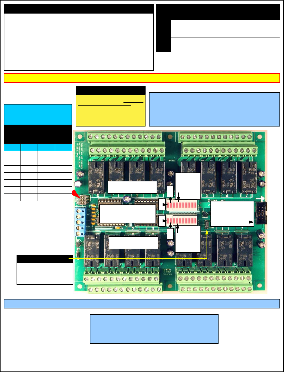
IMPORTANT POWER SUPPLY REQUIREMENTS Status LEDs:
DIP SWITCH SETTINGS HAVE NO EFFECT UNTIL THE CONTROLLER HAS BEEN POWER CYCLED.
Standard Hole Size is .156”.
Standard Inset of Mounting Holes from any edge of the board is .175” from edge to Center of Mounting Hole.
We recommend the use of a #8 Screw with a Minimum .250” Standoff.
The component side of the R45, R410, R85, R810 Pro requires 3/4” minimum clearance.
The component side of any Controller with DPDT in the part number requires 1 1/4” minimum clearance.
The component side of any Relay Controller with 20 or 30 Amp Relay requires 1 1/2” minimum clearance.
NOTE: Some 20 or 30 Amp Relay Controller Varieties require direct connection to the top side of each relay.
Additional clearance for the connectors is highly recommended.
Complete mechanical drawings for each device in the ProXR Series Line can be found on the product
description page of each controller at www.controlanything.com.
Did You Know?
The mechanical relays we have chosen for our control-
lers are rated to easily withstand several million
continuous high-current switching cycles and have
an operational life of more than 10 years. In many
ways, today’s mechanical relays can outlast solid state
relays because of their mechanical ability to handle high
current surges. In addition, the mechanical relays we
have chosen are hermetically sealed, greatly reducing
wear on the contacts by eliminating internal sparking.
RS-232 Data Output
RS-232 Data Input
RS-232 Ground
Power Ground
+12 Volt Input
DIP Switch Settings
38.4K Baud Configuration Mode Allows
you to Store Device Parameters.
On Powerup, All Relays are Tested in
Configuration Mode.
DATA OUT: TTL/OC Jumper
OC232: Open Collector RS-232 Output Used
for Networking Multiple Devices. Requires
RSB Booster in this mode.
RS232: Standard RS-232 Data Output
Mode. This is the default setting.
LEDs Description
1 Heartbeat LED Flashes Quickly most of the time, flashes slowly when a
timing operation is in progress.
2 Data Receive LED Flashes when Valid Data is Received
3 E3C Device Enabled LED is Lit when Device is Enabled (on by default)
4 Data Transmit LED Flashed when Data is Sent Back to User
Switch: 1 2 3
*38.4K Off Off Off
2400 On Off Off
4800 Off On Off
9600 On On Off
19.2K Off Off On
38.4K On Off On
57.6K Off On On
115.2K On On On
1
2
3
4
Relay
Status
LEDs
Relay
Status
LEDs
XR Expansion Port
Allows you to Add
More Relays to your
Controller
Bank 1
Bank 2
Bank 0 Speaks to
all Relay Banks
1) DO NOT USE A WALL WART TYPE UNREGULATED POWER SUPPLY.
2) USE ONLY A COMPUTER GRADE REGULATED SWITCHER SUPPLY RATED AT 12
VOLTS DC, 1.25 AMPS OR GREATER.
3) USE A SUPPLY RATED FOR MORE AMPERAGE WHEN POWERING MULTIPLE
BOARDS.
4) DC POWER SHOULD NEVER TRAVEL GREATER THAN 20 FEET. A SEPARATE
POWER SUPPLY SHOULD BE USED FOR EACH CONTROLLER IF CONTROLLERS
ARE NOT LOCATED WITHIN 20 FEET OF EACH OTHER.
5) RELAY COILS ARE RATED AT 12 VOLTS DC. HIGHER VOLTAGES WILL
SHORTEN THE COIL LIFE. LOWER VOLTAGES MAY CAUSE UNRELIABLE OP-
ERATION, BUT WILL NOT DAMAGE THE CONTROLLER.
6) PROXR SERIES CONTROLLERS CAN BE USED IN 12 VOLT AUTOMOTIVE ELEC-
TICAL SYSTEMS.
Never Install NCD Relay Controllers Near High
Power RF Transmitters, Such as CB Radio and
Emergency Vehicle Voice/Data Transmitters.
These Devices May Cause All Relays to Turn Off.
Please visit our web site for mechanical drawings of the ProXR Series Controller
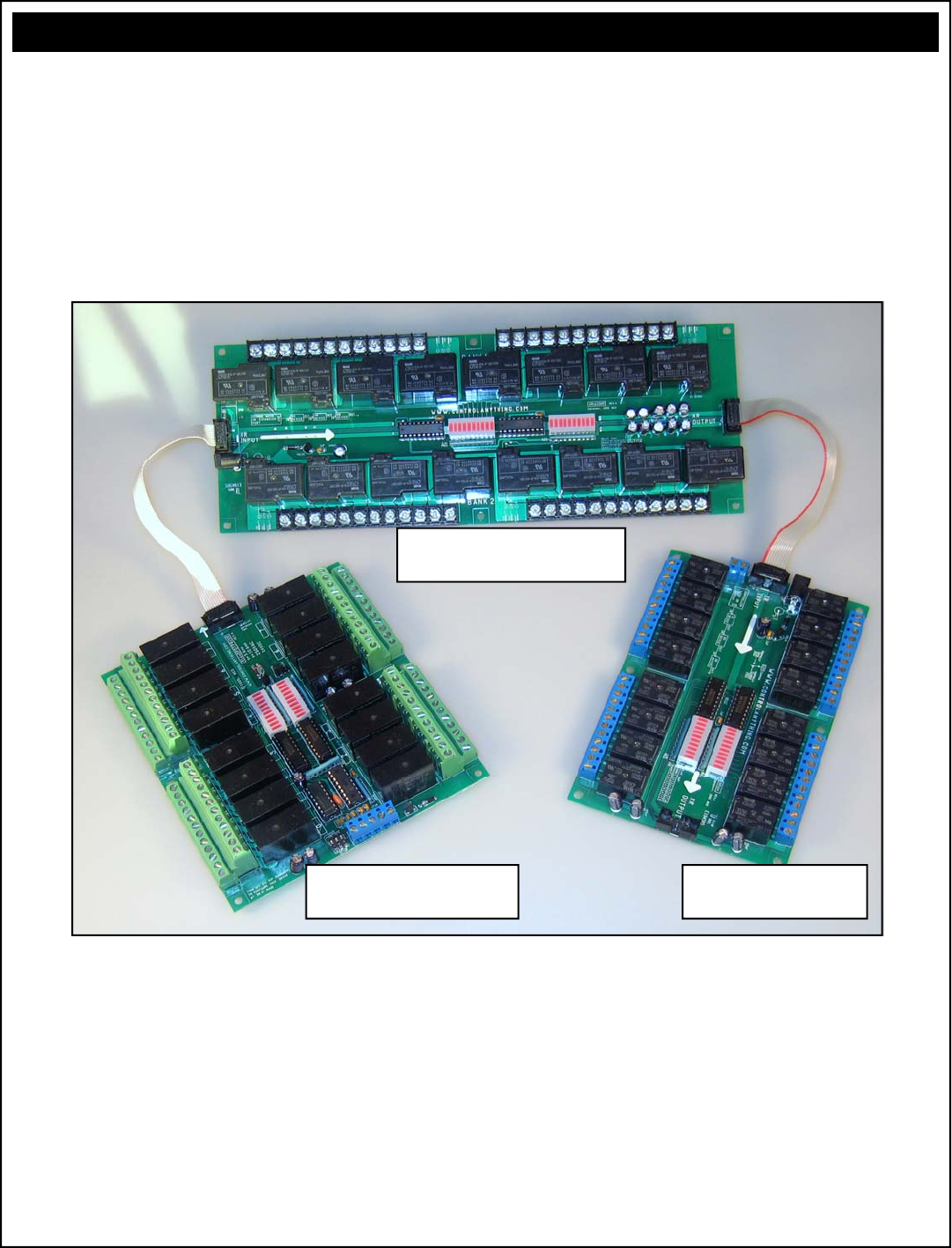
The XR Expansion Port
Adding Relay Banks with the XR Expansion Port
The ProXR Series controllers are equipped with an XR Expansion port.
This port is used to chain relay controllers together, making it easy to
add relay banks as your needs grow. We offer a large line of relay
expansion boards, ready to attach to the XR port of your controller.
The photo below shows how to connect multiple relay banks to a single
ProXR relay controller. You can add all types of relay expansion banks
in any combination to the ProXR series controllers.
R165DPDTPROXR RS-232
Relay Controller
R1620HP 16-Relay 20A High
Power Expansion Controller
XR165 16-Relay 5A
Expansion Controller
Above
The R165DPDTPROXR relay controller is attached to an R1620HP relay controller, which is chained to an XR165 relay control-
ler. The ProXR series controllers can be expanded with any NCD device with part numbers beginning XR. The expansion
cables shown above are included with the XR series relay controllers. In the configuration shown above, there are 6 relay
banks. The ProXR firmware supports a chain of up to 32 relay banks. Each relay controller can be powered by itself (we carry
the appropriate power supply as a product option), or one large supply can be used to power all relay banks (not supplied).
+12
RS-232
Data Out
RS-232
Data In RS-232
Ground
R16 Data Out
R16 Data In
R16 Data Ground
Solder Side of DB9 Female Shown
WARNI NG:
Do NOT Exceed +12.50 Volts on the power inputs
Do NOT use an unregulated wall adapter (wall wart)
Use ONLY a computer grade supply rated at +12 Volts 2.5 Amps or greater
+12
RS-232
Data Out RS-232
Ground
R16 Data In
R16 Data Ground
Solder Side of DB9 Female Shown
WARNING:
Do NOT Exceed +12.50 Volts on the power inputs
Do NOT use an unregulated wall adapter (wall wart)
Use ONLY a computer grade supply rated at +12 Volts 2.5 Amps or greater
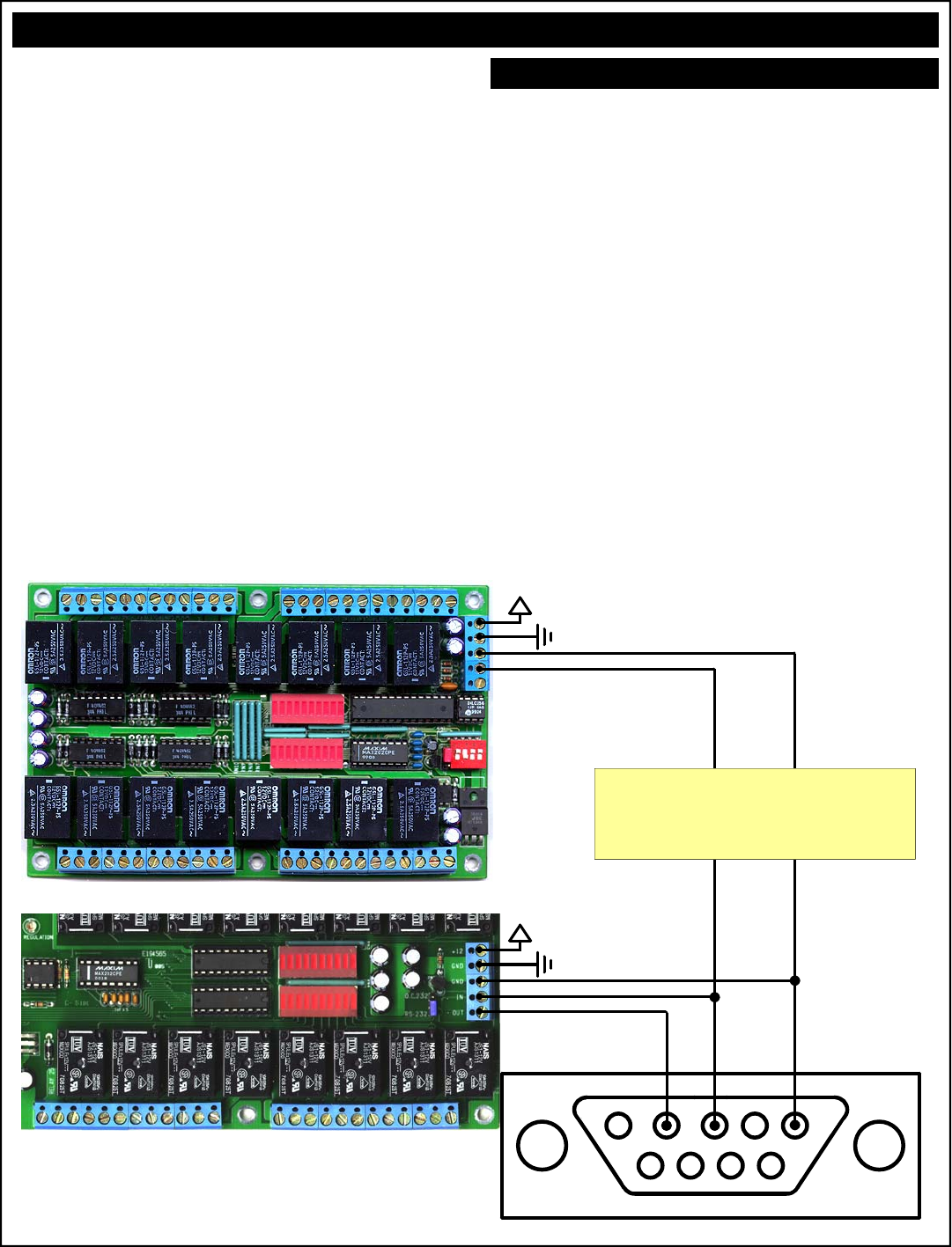
Two-Way Communication:
The ProXR Series Controllers support two-way com-
munication for confirming the receipt of commands and
for reporting the status of the relays back to the host
computer.
The ProXR Series Controllers should be connected as
shown below when using this device for the first time.
Even if you plan to connect several controllers to a sin-
gle serial port, this wiring diagram must first be used to
program the device number into the controller.
Test Software Provided on our Web Site expxects this
wiring configuration.
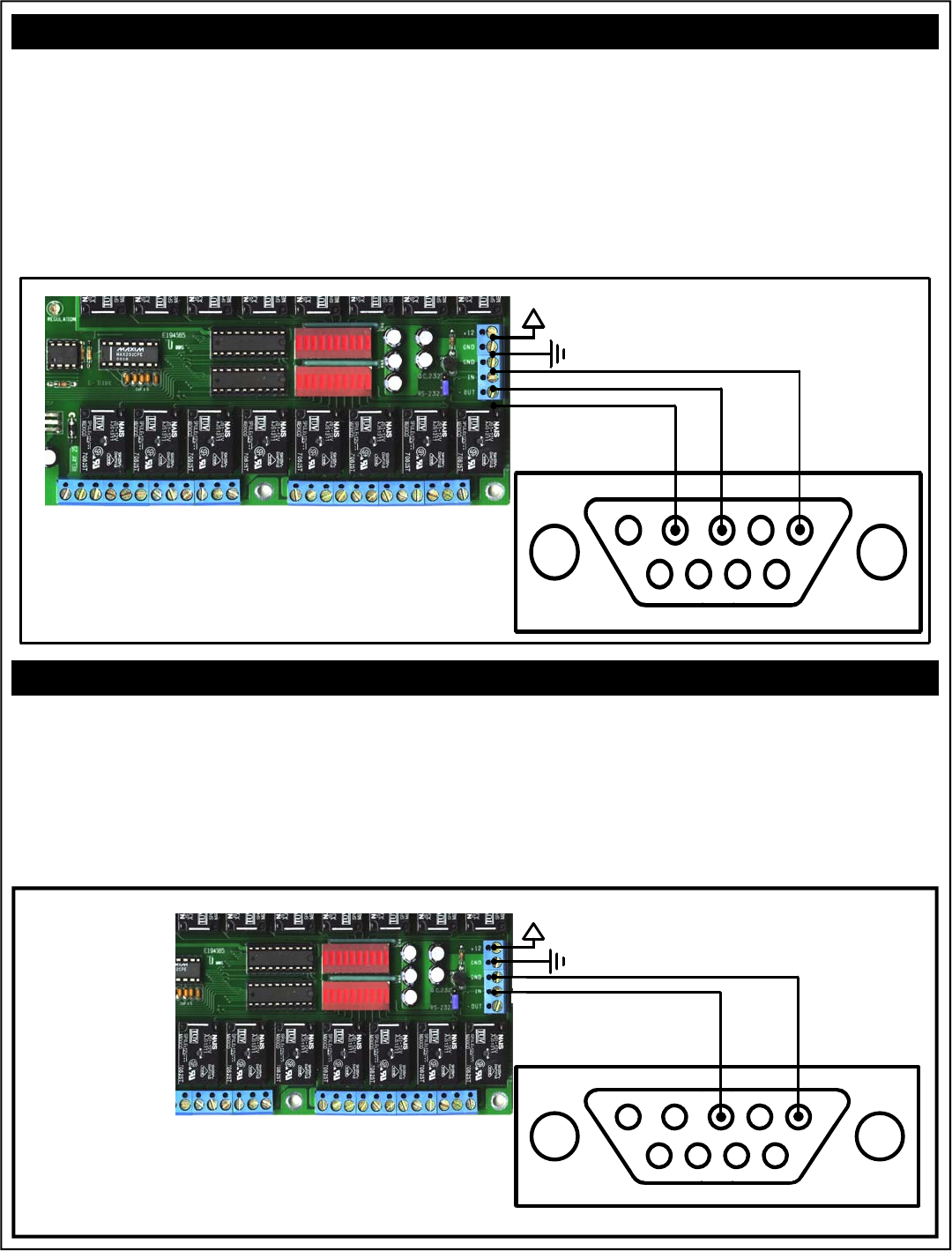
The ProXR Series Controllers can be connected to a
computer or microcontroller using as little as two wires.
When used in 1-way mode, reporting should be turned off
for highest communication speed. Turning off reporting
will allow you to send commands to the ProXR Series
Controllers much faster, but it is impossible to ask the
controller for the status of relays when wired as shown
below.
Reporting Mode is activated by sending ASCII charac-
ter codes 254, 27.
Reporting Mode is deactivated by sending ASCII char-
acter codes 254, 28.
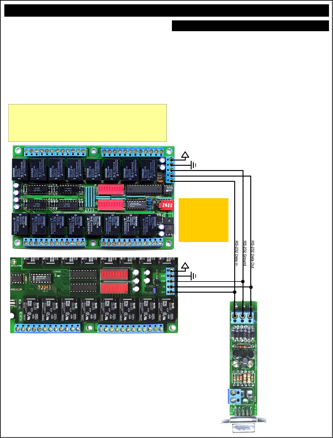
ProXR One-Way Communication:
This illustration shows the R32 relay board, this wiring con-
figuration is generically compatible with all NCD relay con-
trollers, including “Pro” and “ProXR” series with a 5-
position terminal block.
This illustration shows the R32 relay board, this wiring
configuration is generically compatible with all NCD relay
controllers, including “Pro” and “ProXR” series with a 5-
position terminal block.
+12
R16 Data In
R16 Data Ground
WARNING:
Do NOT Exceed +12.50 Volts on the power inputs
Do NOT use an unregulated wall adapter (wall wart)
Use ONLY a computer grade supply rated at +12 Volts 2.5 Amps or greater
+12
RS-232
Data Out
RS-232
Data In RS-232
Ground
R16 Data Out
R16 Data In
R16 Data Ground
Solder Side of DB9 Female Shown
Multiple NCD Devices can be connected to a single se-
rial port and controlled individually. This example shows
an R16 and an R32 connected to a single serial port.
Before using this wiring configuration, each device must
be programmed with a unique device number (See E3C
Commands in Both Manuals for Details). Once a device
number has been stored into each controller this wiring
configuration may be used to control up to 256 different
relay boards or other NCD devices in any combination.
This wiring configuration only allows 2-way communica-
tion with the R32. Relay status information cannot be
read from the R16.
When all boards are first powered up, all devices will
respond to incoming commands. Use E3C Command
252 to speak to one device at a time. Send 252, 0, any
subsequent commands should be for the R32, Device 0.
Send 252, 1, any subsequent commands should be for
the R16, Device 1.
This E3C Command 252 is useful when mixing different
types of controllers on a single serial port.
Multiple Relay Controllers: Two-Way & One-Way Hybrid Communication
Device 0
Programmed Into controller
using the Program Device
Number Command. Page 9.
Device 1
Programmed Into controller .
See R16 Manual
Step 1: Store a Device Number from 0 to 255 into
Each Controller. Example Shows Device 0 and 1.
Step 2: Route Commands to Device 0 Only by Send-
ing the Following Commands:
ASCII 254 ‘Enter Command Mode
ASCII 252 ‘Select a Device to Control Command
ASCII 0 ‘Set Device to Control to 0
Step 3: Activate Relay 1 on Device 0 (R32)
ASCII 254 ‘Enter Command Mode
ASCII 1 ‘Relay On Command
ASCII 0 ‘Turn On Relay 1
Step 4: Route Commands to Device 1 Only by Send-
ing the Following Commands:
ASCII 254 ‘Enter Command Mode
ASCII 252 ‘Select a Device to Control Command
ASCII 1 ‘Set Device to Control to 1
Step 3: Activate Relay 1 on Device 1 (R16)
ASCII 254 ‘Enter Command Mode
ASCII 16 ‘Turn Relay 0 On
Multiple Device Control: Quick Example
R16 Relay Controller:
R32 Relay Controller:
Illustration shows R32 relay board, this wiring configura-
tion is the same for all NCD relay controllers, including
“Pro” series with a 5-position terminal block.
NOTICE:
Commands Shown On This Page Do NOT Represent
Valid Commands for ProXR Series Controllers
Wiring Diagram Shown is Generically Compatible
with the ProXR Series Controllers.
+12
R16 Data Out
R16 Data In
R16 Data Ground
WARNING:
Do NOT Exceed +12.50 Volts on the power inputs
Do NOT use an unregulated wall adapter (wall wart)
Use ONLY a computer grade supply rated at +12 Volts 2.5 Amps or greater
+12
R16 Data Out
R16 Data In
R16 Data Ground
Multiple Relay Controllers: Two-Way Communication
Our relay controllers support two-way communication to mul-
tiple devices using the RSB serial booster. Jumpers must be
set for Open Collector data transmission. See the appropri-
ate manual for your relay controller. This is ONLY required
when using the RSB serial booster. The RSB serial booster
should be used when controlling several devices over long
distances (has been tested in excess of 500 feet). Actual
reliability over long distances depends greatly on baud rate
and type of wire used. Experimentation will be required.
Always start at the lowest baud rate and work your way up.
A unique device number should be programmed into each
device prior to using this example.
Limitations:
1) The RSB Serial Booster is NOT Compatible with Baud
Rates above 38.4K Baud.
2) It is estimated that a single serial booster can control
256 Relay controllers. This has not been tested, and
may be subject to other baud rate or distance limita-
tions. Please contact us if you have application prob-
lems with this configuration.
Connect up to 256 de-
vices on a Single Serial
Port. Each R16 MUST
be Programmed with a
Unique Device Number.
Jumpers MUST be
Set between the
Lower Two Termi-
nals. Set jumpers
opposite of what is
shown in these
photos.
Device 1
The Device Number is Programmed Into
Controller using the E3C Command Set.
Device 0
The Device Number is Programmed Into
Controller using the E3C Command Set.
1) DO NOT USE A WALL WART TYPE UNREGULATED POWER
SUPPLY.
2) USE ONLY A COMPUTER GRADE REGULATED SWITCHER
SUPPLY RATED AT 12 VOLTS DC, 1.25 AMPS OR GREATER.
3) USE A SUPPLY RATED FOR MORE AMPERAGE WHEN POW-
ERING MULTIPLE BOARDS.
4) DC POWER SHOULD NEVER TRAVEL GREATER THAN 20
FEET. A SEPARATE POWER SUPPLY SHOULD BE USED FOR
EACH CONTROLLER IF CONTROLLERS ARE NOT LOCATED
WITHIN 20 FEET OF EACH OTHER.
5) RELAY COILS ARE RATED AT 12 VOLTS DC. HIGHER VOLT-
AGES MAY SHORTEN THE COIL LIFE. LOWER VOLTAGES
MAY CAUSE UNRELIABLE OPERATION, BUT WILL NOT DAM-
AGE THE CONTROLLER.
6) IT IS SAFE TO CONTROL ANY +12 VOLT RELAY CONTROLLER
FROM AN AUTOMOTIVE POWER SYSTEM. YOU MAY DISRE-
GARD THE +12.5 VOLT WARNING ON THIS PAGE AND THE
PREVIOUS PAGE IN THIS APPLICATION.
Selecting a Power Supply
PLEASE SEE THE
MANUAL FOR THE
RSB SERIAL
BOOSTER FOR
COMPLETE WIRING
INFORMATION.
Illustration shows R32 relay board, this wiring configuration is
the same for all NCD relay controllers, including “Pro” series
with a 5-position terminal block.
ProXR Version NOTICE:
ProXR Series Controllers are wired in the same way shown below, and are
generically compatible with the diagrams shown on this page. ProXR
Series Controllers also use the RS232/OC232 Jumper Referenced on this
page. Dip Switch Settings Shown Below do Not Apply to the ProXR Series
Controllers. Do Not Exceed 38.4K Baud when using the RSB Booster.

Sending Commands to the ProXR Series Relay Controllers
The ProXR Series Controllers are capable of sending and re-
ceiving data via RS-232 serial communications. ProXR Con-
trollers are compatible with just about any computer or micro-
controller ever produced, including the Macintosh, Amiga, Basic
Stamp, and of course, Windows & DOS based machines.
Regardless of the system you are using, you will need access
to a programming language that supports program control of
the serial port on your computer.
A terminal program is not suitable for controlling NCD Devices
unless it supports transmission of Binary ASCII Character
Codes. Commands should be sent using ASCII character
codes 0-255 rather than ASCII characters (A, B, C etc.). See
“ASCII Codes vs. Characters” on this page.
Most systems require you to open the appropriate serial port
(COM port) prior to sending or receiving data.
Because there are so many different ways to send and receive
data from various languages on various platforms, we will pro-
vide generic instructions that can be easily converted to your
favorite language.
For example, if this manual says “Send ASCII 254”, the user
will need to translate this instruction into a command that is
capable of sending ASCII character code 254.
To Send ASCII 254 from Visual Basic, you will use the following
line:
MSComm1.Output = Chr$(254)
In Qbasic, you can send ASCII 254 using the following line of
code:
Print #1, Chr$(254);
Note that sending ASCII character code 254 is NOT the same
as sending ASCII characters 2, 5, and 4 from a terminal pro-
gram. Typing 2, 5, and 4 on the keyboard will transmit three
ASCII character codes.
In your program, you may want to ask ProXR Controllers for the
current status of relays, just to confirm their activation. If so,
your programming language will support commands for reading
data from the serial port.
For your convenience, we have provided several programming
examples in Visual Basic 6 for controlling the ProXR Series
Controller. These examples should greatly speed development
time. You may want to visit www.controleverything.com for
the latest software and programming examples.
Programming examples for the ProXR Series are much more
extensive for Visual Basic 6 users than for any other program-
ming language. If you are not a VB programmer, you may con-
sider looking at the VB6 source code, as it is easily translated
into other popular languages.
Regardless of your programming background, the pro-
vided Visual Basic 6 source code is very easy to under-
stand and will likely resolve any communication questions
you may have. VB6 programming examples may be
viewed in any text editor.
The differences between ASCII codes and ASCII characters
tend to generate a lot of confusion among first-time RS-232
programmers. It is important to understand that a computer
only works with numbers. With regard to RS-232 data, the
computer is only capable of sending and receiving numbers
from 0 to 255.
What confuses people is the simple idea that the numbers 0 to
255 are assigned letters. For instance, the number 65 repre-
sents the letter A. The number 66 represents the letter B.
Every character (including numbers and punctuation) is as-
signed a numeric value. This standard of assignments is called
ASCII, and is a universal standard adopted by all computers
with an RS-232 serial port.
ASCII characters codes can be clearly defined as numbers
from 0 to 255.
ASCII characters however are best defined as letters, A, B, C,
D, as well as punctuation, !@#$%, and even the numbers 0-9.
Virtually all programming languages permit you to send ASCII
in the form of letters or numbers. If you wanted to send the
word “Hello” out the serial port, it is much easier to send the
letters H, e, l, l, and o than it is to send the ASCII character
codes that represent each letter.
For the purposes of controlling NCD devices however, it is
much easier to build a numeric command set. Especially when
communicating to devices where you want to speak to lots of
outputs (which are numbered), inputs (which are also num-
bered), or control specific devices using their device number
(from 0 to 255).
Put simply, it is easier to control NCD devices using ASCII
character codes 0 to 255 than it is to use ASCII characters A,
B, C, D, etc.
Because terminal programs are ASCII character based, it may
be difficult to generate the proper series of keystrokes that
would be necessary to activate a particular function. Therefore,
they are not suitable for controlling NCD devices. In a real
world control application, a terminal program would not likely be
used to control NCD devices anyway. Therefore, a program-
ming language that supports the transmission and reception of
ASCII character codes 0 to 255 is highly recommended.
ASCII Codes vs. Characters
Visual Basic 4, 5, 6
We have posted a Visual Basic 6 tutorial in the “Developers Toolbox”
section of our web site. This tutorial is available by clicking here. This
same tutorial can be also be downloaded along with a .NET tutorial in
the Universal Device Manual available from our web site by clicking
here.
.NET Express
You can also use Visual Basic Express to speak to NCD devices. VB
Express is free from Microsoft. At the time of writing, Microsoft offers a
free download by clicking here. Click the large camouflaged
“Download Now” button on the right side of the screen.
We have also posted a tutorial for using .NET Express in the Universal
Device Manual, available from our web site by clicking here.

The E3C Command Set: Software Control of Multiple NCD Devices
The E3C command set allows you to control up to 256 NCD
devices from a single serial port. It is OK to mix different types
of devices, as long as the devices are E3C compliant. The
R4x/R8x Pro relay controllers support the full set of E3C com-
mands, plus a set of extended commands for storing and recall-
ing the device number.
How does E3C Work?
First of all, each device must be assigned a device number
from 0 to 255. The ProXR Contrroller must be programmed
with a device number, which is accomplished using the “Store
Device Number” command shown below.
E3C stands for Enabled 3-Wire Communication. Put simply, all
devices will respond to your commands when powered up.
Using the E3C command set, you can specify which devices
will listen and which devices will ignore your commands. Note
that E3C commands are never ignored by any device, regard-
less of the commands you send to the controller.
The number to the left of each command indicates the ASCII
character code that must be sent to issue the command. All
commands must be preceded with ASCII character code 254 to
place the device in command mode. See examples at right.
254, 248 Enable All Devices:
Tells all devices to respond to your commands.
254, 249 Disable All Devices:
Tells all devices to ignore your commands.
254, 250 Enable a Selected Device:
Tells a specific device to listen to your commands.
254, 251 Disable Selected Device:
Tells a specific device to ignore your commands.
254, 252 Enable Selected Device Only:
Tells a specific device to listen to your commands, all other
devices will ignore your commands.
254, 253 Disable a Selected Device Only:
Tells a specific device to ignore your commands, all others will
listen.
The ProXR Series Controllers support three additional E3C
commands which should only be used when a single device is
attached to your serial port. Extended commands will report
back to the computer.
254, 255 Store Device Number:
Stores the device number into the controller. The device num-
ber takes effect immediately. The enabled/disabled status of
the device is unchanged.
254, 246 Recall Device Identification:
This command reports back 4 bytes of data:
ProXR Device ID Part 1: 1
ProXR Device ID Part 2: 0
ProXR Firmware Version: 17 (or newer)
ProXR Year of Firmware Production: 205 (or newer)
ProXR E3C Device Number
254, 247 Recall Device Number:
Reads the stored device number from the controller.
The E3C command set is easily used from any program-
ming language that supports serial communication. The
following Visual Basic 6 Example source code demon-
strates subroutines that can be used to control which de-
vices will listen and which devices will ignore your com-
mands.
Most commands issued to the ProXR Series Controllers
are acknowledged by sending ASCII character code 85
back to the host computer (when reporting is turned on).
E3C commands are not acknowledged regardless of the
reporting mode.
'Enable All E3C Devices
MSComm1.Output = Chr$(254) 'Enter Command Mode
MSComm1.Output = Chr$(248) 'E3C Enable All Device Command
'Disable All E3C Devices
MSComm1.Output = Chr$(254) 'Enter Command Mode
MSComm1.Output = Chr$(249) 'E3C Disable All Device Command
'Enable A Specific E3C Devices, Other Devices will be unchanged
MSComm1.Output = Chr$(254) 'Enter Command Mode
MSComm1.Output = Chr$(250) 'E3C Disable Specific Device Command
MSComm1.Output = Chr$(Device) 'Device Number that will be Disabled
'Disable A Specific E3C Devices, Other Devices will be unchanged
MSComm1.Output = Chr$(254) 'Enter Command Mode
MSComm1.Output = Chr$(251) 'E3C Disable Specific Device Command
MSComm1.Output = Chr$(Device) 'Device Number that will be Disabled
'Disable All E3C Devices Except (Device)
MSComm1.Output = Chr$(254) 'Enter Command Mode
MSComm1.Output = Chr$(252) 'E3C Disable All Device Except Command
MSComm1.Output = Chr$(Device) 'Device Number that will be Active
'Enable All E3C Devices Except (Device)
MSComm1.Output = Chr$(254) 'Enter Command Mode
MSComm1.Output = Chr$(253) 'E3C Enable All Device Except Command
MSComm1.Output = Chr$(Device) 'Device Number that will be Inactive
'Store an E3C Device Number into the Controller
MSComm1.Output = Chr$(254) 'Enter Command Mode
MSComm1.Output = Chr$(255) 'E3C Store Device Number Command
MSComm1.Output = Chr$(Device) 'Device Number that will be Stored
WaitForReply 'Wait for Acknowledgement
'Store an E3C Device Number into the Controller
MSComm1.Output = Chr$(254) 'Enter Command Mode
MSComm1.Output = Chr$(246) 'Get Device Information
Debug.Print GetData 'Device ID Number Part 1
Debug.Print GetData 'Device ID Number Part 2
Debug.Print GetData 'Device Firmware Version
Debug.Print GetData 'Device Year of Manufacture 205 = 2005, 206 = 2006
'Read the E3C Device Number from the Controller
MSComm1.Output = Chr$(254) 'Enter Command Mode
MSComm1.Output = Chr$(247) 'E3C Get Device Number Command
Debug.Print GetData ‘Display E3C Device Number
'Read a Byte of Data from the Serial Port
Public Function GetData()
Do 'Wait for Device to Reply
DoEvents 'Allow Windows to MultiTask
Until MSComm1.InBufferCount > 0 'If the Device Replies
GetData = Asc(MSComm1.Input) 'Get Data from Device
End Fucntion
The E3C Command Set
Extended E3C Commands
E3C Visual Basic Programming Examples
Sample Code: The E3C Command Set
ProXR Version NOTICE:
ProXR Series Controllers Only Allow you to use the “Store E3C Device
Number” Function while in “Configuration Mode”. This prevents acciden-
tal modification of the E3C device number under normal operation if an
incorrect series of commands are sent to the controller. So make sure the
ProXR Controller is in configuration mode when storing the E3C device
number. Simply turn off all DIP Switches and Power Cycle the controller to
enter configuration mode.

STOP HERE:
VERY IMPORTANT READING ON THIS PAGE
Understanding Relay Banks and Basic Control Concepts:
A Relay Bank is Simply a Group of 8 Relays. The ProXR Series Controllers allow you to control up to 256 relays (32 relay banks).
You control which bank of relays you are speaking to at all times. It is VERY IMPORTANT that you understand that there are two
ways to specify which relay bank you are talking to. These topics will be discussed in greater length later in this manual, providing
you with specific instructions and program examples. This page will help prepare you for seeing two different command that do
the same thing. In this manual, you will see the work “Bank”. This word should be equated to a number from 0 to 32. A value of 1
speaks to relay bank 1 (the first 8 relays on the board). A value of 2 speaks to relay bank 2 (the second group of 8 relays on the
board). A value of 32 speaks to the last group of 8 relays (which is connected to the main controller using the XR expansion
ports). A value of 0 speaks to all banks of relays at one time. When bank 0 is selected, you can then specify a command to turn
on relay 1, and relay 1 on all relay banks will be activated. There will be more examples of this and detailed information on each
command. But understanding the concept of controlling multiple relays across multiple banks is very important to your under-
standing how our controller command set is organized.
Bank Directed Commands:
a) You Specify a Relay Bank (there is a command you will send just for this purpose).
b) All Subsequent Commands will be directed to the previously specified relay bank.
c) You Specify a different Relay.
d) All Subsequent Commands will be directed to the new relay bank you have specified.
Bank Specified Commands:
a) You Specify a Relay Bank with every command.
While this method is slightly slower, it ensures commands are always directed to the correct relay bank.
Understanding Relay Bank Refreshing:
Controlling Multiple Banks
Under normal operation, you will send a command to the relay controller, and the relay controller will respond to your command by
activating or deactivating a relay. This system works well if you only need to control 1-8 relays, but it does not necessarily work
very well if you are taking advantage of the XR Expansion ports, allowing you to control up to 256 relays (32 relay banks). In these
cases, you may want to set the status of all relays at the exact same time. The easiest way to do this is to turn off automatic relay
refreshing. Once turned off, you can use the relay control command set to activate relays, but the commands will not appear to
have any effect. The effects will not be seen until you manually refresh the relay bank. Rest assured, when auto refreshing is off,
your relay control commands are working, the processor memory is copied to the physical relay bank memory when you manually
refresh the relays. Follow this methodology to set the status of lots of relays at one time across multiple banks:
a) Turn Off Relay Bank Auto Refreshing.
b) Use Relay Control Command to Activate Different Relays on Different Banks.
These commands will not appear to work, they will only modify internal memory.
c) Send the Manual Refresh Command to Update All Relays at One Time.
STOP HERE:
VERY IMPORTANT READING ON THIS PAGE
Command codes will be shown in blue. Send these values to the controller to activate the command.
Any returned data will be shown in green.
Warnings and special notes will be shown in red.

Relay Banking Commands
The ProXR Series Controllers allow you to control up to 256 relays. Relays are
divided into groups of 8 called Banks, and are addressed by their bank number.
For instance, a ProXR series controller with 32 on-board relays has four on-board
banks, the on-board relays respond to Bank values of 1-4. If you use the XR
Expansion port to add another bank of 24 relays, then you will need to specify
bank values of 5-7 to control the extra relays. The firmware doesn’t actually know
how many relays are attached to the relay controller, but it assumes there are 256
relays (banks values 1-32, which is the maximum supported number of relays for
Version 1.0 firmware).
In this manual, you will see two commands that appear to do the same thing, for
example:
254,0-7 Turn Off Individual Relays
254,100-107, Bank Turn Off Individual Relays in Bank
254,8-15 Turn On Individual Relays
254,108-115 Turn On Individual Relays in Bank
254,16-23 Get the Status of an Individual Relay
254,116-123, Bank Get the Status of an Individual Relay in Bank
While the outcome is the same, these commands function in slightly different
ways.
For instance:
254,8 Turn On Relay 1
To make this command work, you will send a 254, then a 8 to activate a relay. By
default, relay bank 1 will be affected by this command. However, you can redirect
this command to a different relay bank using the following command:
254,49,2 Direct Commands to Relay Bank 2
Then you can send:
254,8 Turn On Relay 1 in Bank 2
Here are more examples:
254,49,1 Direct Commands to Relay Bank 1
254,8 Turn On Relay 1 in Bank 1
254,49,2 Direct Commands to Relay Bank 2
254,8 Turn On Relay 1 in Bank 2
254,9 Turn On Relay 2 in Bank 2
254,10 Turn On Relay 3 in Bank 2
254,49,3 Direct Commands to Relay Bank 3
254,8 Turn On Relay 1 in Bank 3
254,11 Turn On Relay 4 in Bank 3
254,12 Turn On Relay 5 in Bank 3
254,13 Turn On Relay 6 in Bank 3
254,14 Turn On Relay 7 in Bank 3
254,49,0 Direct Commands to All Relay Banks
254,8 Turn On Relay 1 in All Relay Banks
This command structure has the advantage of being very fast and efficient. How-
ever, if power to the controller is ever lost, commands will automatically be di-
rected to bank 1 when power to the controller has been restored.
We have also included a set of commands that require you to specify the bank as
part of the command structure. This ensures commands are always directed to
the correct relay bank. Here are a few examples:
254,108, 1 Turn On Relay 1 in Bank 1
254,108, 2 Turn On Relay 1 in Bank 2
254,109, 2 Turn On Relay 2 in Bank 2
254,110, 2 Turn On Relay 3 in Bank 2
254,108, 3 Turn On Relay 1 in Bank 3
254,111, 3 Turn On Relay 4 in Bank 3
254,112, 3 Turn On Relay 5 in Bank 3
254,112, 0 Turn On Relay 5 in All Relay Banks (Bank 0)
Relay Refreshing:
Controlling Large Groups of Relays
The ProXR Series Controllers allow you to manually or automatically refresh relay
banks. When you first receive your ProXR Series Controller, Relay Refreshing is
turned on. Meaning every time you send a relay control command, the relays will
respond to your commands.
Turning off relay refreshing allows you to control when the relays actually switch.
When refreshing is turned off, you can send relay control commands to the ProXR
controller, and the controller will work just like normal, but the relays will never
change state.
You can then use the Manual Refresh command to set the status of all relays at
one time. Weather you are controlling 1 or 235 relays, you will be able to refresh
all relays at one time to any given state by taking manual control of the relay
refreshing capabilities. Here are some simple programming examples in VB:
254,25 Turn On Automatic Relay Refreshing
Setting Automatically Stored when in Configuration Mode
MSComm1.Output = Chr$(254) 'Enter Command Mode
MSComm1.Output = Chr$(25) 'Turn ON Refresh Command
(When Reporting Mode is ON, controller will send ASCII Code 85 to Acknowledge this command)
254,26 Turn Off Automatic Relay Refreshing
Setting Automatically Stored when in Configuration Mode
MSComm1.Output = Chr$(254) 'Enter Command Mode
MSComm1.Output = Chr$(26) 'Turn Off Refresh Command
(When Reporting Mode is ON, controller will send ASCII Code 85 to Acknowledge this command)
254,36 Report Back Stored Refresh Settings
This command reports back a 0 or 1, indicating weather automatic refreshing is
Off or On when power is first applied to the controller.
MSComm1.Output = Chr$(254) 'Enter Command Mode
MSComm1.Output = Chr$(36) 'Read Default Powerup Refreshing Status
(Controller will report back ASCII Character Code 0 or 1)
254,37 Manually Refresh Relay Bank
This command stores the current status of relay refreshing in non-volatile mem-
ory. The next time the relay controller is powered up, refreshing will be set to the
stored state.
MSComm1.Output = Chr$(254) 'Enter Command Mode
MSComm1.Output = Chr$(37) 'Manually Refresh Relays Command
(When Reporting Mode is ON, controller will send ASCII Code 85 to Acknowledge this command)
Application: Manual Refreshing Relay Banks
This simple application example demonstrates the process required to activate
more than 8 relays simultaneously. In the example below, we will demonstrate
how to apply the Manual Refreshing command to large groups of relays.
Step 1: Turn Off Automatic Refreshing
MSComm1.Output = Chr$(254) 'Enter Command Mode
MSComm1.Output = Chr$(26) 'Turn Off Refresh Command
(When Reporting Mode is ON, controller will send ASCII Code 85 to Acknowledge this command)
Step 2: Activate Several Relays on Several Relay Banks
(note: relays will not be updated, they will not appear to change).
MSComm1.Output = Chr$(254) 'Enter Command Mode
MSComm1.Output = Chr$(108) 'Turn On Relay 1
MSComm1.Output = Chr$(1) 'On Bank 1
(When Reporting Mode is ON, controller will send ASCII Code 85 to Acknowledge this command)
MSComm1.Output = Chr$(254) 'Enter Command Mode
MSComm1.Output = Chr$(111) 'Turn On Relay 4
MSComm1.Output = Chr$(2) 'On Bank 2
(When Reporting Mode is ON, controller will send ASCII Code 85 to Acknowledge this command)
MSComm1.Output = Chr$(254) 'Enter Command Mode
MSComm1.Output = Chr$(113) 'Turn On Relay 6
MSComm1.Output = Chr$(3) 'On Bank 3
(When Reporting Mode is ON, controller will send ASCII Code 85 to Acknowledge this command)
...You can keep adding relay control commands to activate different relays on different banks, but
keep in mind, these commands will not appear to function. These commands are changing the
memory pattern for the relays inside the controller. You will not see the effects of your changes until
you send a Manual Refresh command. You can return to automatic refreshing at any time. Turning
on automatic refreshing does NOT refresh the relays until the NEXT relay control command is
issued.
Step 3: Update All Relays at the Same Time (Manually Refresh)
MSComm1.Output = Chr$(254) 'Enter Command Mode
MSComm1.Output = Chr$(37) 'Manually Refresh Relays Command
(When Reporting Mode is ON, controller will send ASCII Code 85 to Acknowledge this command)

The ProXR Command Set
The ProXR Series Controllers support an extensive command set, used
to control relays, set operation modes, and store and recall relay status.
Most users will only use a few of the functions built into this controller.
The best way to learn the capabilities of the ProXR series is to carefully
read through the command set. The “plain English” examples provide a
quick, easy to understand definition of each command.
The number in blue to the left of each command indicates the ASCII
character code that must be sent to issue the command. All commands
must be preceded with ASCII character code 254 to place the device in
command mode. See examples at right.
Some commands require that you specify a Bank value from 0-32,
selecting the relay bank you would like to control. A value of 0 selects
all banks. Bank values of 1-4 control up to 32 On-Board relays. When
powered up, the default Bank value in the controller is always 1.
254,0-7 Turn Off Individual Relays
254,100-107, Bank Turn Off Individual Relays in Bank
254,8-15 Turn On Individual Relays
254,108-115 Turn On Individual Relays in Bank
254,16-23 Get the Status of an Individual Relay
254,116-123, Bank Get the Status of an Individual Relay in Bank
This command allows you to read the on/off status of an individual re-
lay. 16 (or 116) corresponds to relay 1, 23 (or 123) corresponds to
relay 8. This command will return a 1 indicating the relay is ON or a 0
indicating the relay is OFF.
NOTICE: A BANK VALUE OF 0 IS INVALID FOR THIS COMMAND.
RETURNED RESULTS MAY BE UNPREDICTABLE.
254, 24 Get the Status of All Relays
254, 124, Bank Get the Status of All Relays in Bank
This command allows you to read the status of a single bank of relays.
A value of 0-255 is returned indicating the status of all 8 relays. The
binary pattern of the value returned directly corresponds to the on/off
status of each of the 8 relays in the selected relay bank. If the cur-
rently selected relay bank is 0, or if you specify relay bank 0, then the
status of all 32 relay banks will be sent. In this condition, your program
should be written to read 32 bytes of data from the serial port.
254, 27 Turn Reporting Mode ON
254, 28 Turn Reporting Mode OFF
This command sets and stores (in non-volatile EEPROM while in con-
figuration mode only) the reporting mode status. Reporting mode, by
default, is ON, meaning every time a command is sent to the controller,
the controller will send an 85 back to the computer, indicating that the
command has finished executing your instructions. We recommend
leaving it on, but doing so requires 2-Way communication with the con-
troller. You should turn it off if you intend to use 1-Way communication
only. A delay between some commands may be required when using
1-Way communications. For optimum reliability, leave reporting mode
on and use 2-Way communications with the ProXR Series controllers.
NOTE: Reporting Mode may be turned on or off at any time. The
default power-up status of reporting mode is ONLY stored when
the device is in configuration mode (all dip switches off when the
controller is powered up).
A Many Visual Basic 6 programming examples are provided in the
following pages to assist in the development of software for controlling
the ProXR Series relay controllers. Additional source code can be
found on our web site at www.controleverything.com.
254,0 Turn Off Relay 0 in Selected Bank
254,100,1 Turn Off Relay 0 in Bank 1
254,8 Turn On Relay 0 in Selected Bank
254,108,2 Turn On Relay 0 in Bank 2
These commands are used to turn a relay on or off under computer control. Here
is an actual code sample for VB6 that shows how to use these commands:
MSComm1.Output = Chr$(254) 'Enter Command Mode
MSComm1.Output = Chr$(8) 'Activate Relay 0 on the Currently Selected Relay Bank
(When Reporting Mode is ON, controller will send ASCII Code 85 to Acknowledge this command)
MSComm1.Output = Chr$(254) 'Enter Command Mode
MSComm1.Output = Chr$(108) 'Activate Relay 0
MSComm1.Output = Chr$(2) 'In Relay Bank 2
(When Reporting Mode is ON, controller will send ASCII Code 85 to Acknowledge this command)
254,16 Read the Status of Relay 0 in Selected Bank
254,116,2 Read the Status of Relay 0 in Bank 2
254,117,5 Read the Status of Relay 1 in Bank 5
MSComm1.Output = Chr$(254) 'Enter Command Mode
MSComm1.Output = Chr$(16) 'Read On/Off Status of Relay 0 on Currently Selected Relay Bank
(Controller will report back ASCII Character Code 0 or 1 indicating relay status)
MSComm1.Output = Chr$(254) 'Enter Command Mode
MSComm1.Output = Chr$(116) 'Read On/Off Status of Relay 0
MSComm1.Output = Chr$(2) 'In Relay Bank 2
(Controller will report back ASCII Character Code 0 or 1 indicating relay status)
254,24 Read the Status of All 8 Relays in a Selected Bank
254,124,2 Read the Status All 8 Relay in Bank 2
254,124,0 Read the Status of All 8 Relays in All 26 Banks
MSComm1.Output = Chr$(254) 'Enter Command Mode
MSComm1.Output = Chr$(24) 'Read Status of All Relays in Currently Selected Relay Bank
(Controller will report back ASCII Character Codes 0-255, Convert to Binary to See Relay Pattern)
MSComm1.Output = Chr$(254) 'Enter Command Mode
MSComm1.Output = Chr$(124) 'Read Status of All Relays
MSComm1.Output = Chr$(2) 'In Relay Bank 2
(Controller will report back ASCII Character Codes 0-255, Convert to Binary to See Relay Pattern)
MSComm1.Output = Chr$(254) 'Enter Command Mode
MSComm1.Output = Chr$(124) 'Read Status of All Relays
MSComm1.Output = Chr$(0) 'In ALL Relay Banks
(Controller will report back 26 ASCII Values from 0 to 255, Indicating the Status of all 26 Relay
Banks, Beginning with Bank 1. Convert Returned Values to Binary to See Actual Relay Pattern)
NOTE: USE OTHER RELAY CONTROL COMMANDS TO SET RELAYS TO THE DESIRED
POWERUP STATE BEFORE ISSUEING THIS COMMAND. FOR INSTANCE, IF YOU WANT ALL
RELAYS TO COME ON AT POWERUP, USE OTHER RELAY CONTROL COMMANDS TO ACTI-
VATE ALL RELAYS, THEN ISSUE THIS COMMAND. THE NEXT TIME POWER IS APPLIED TO
THE CONTROLLER, ALL RELAYS WILL AUTOMATICALLY ACTIVATE.
MSComm1.Output = Chr$(254) 'Enter Command Mode
MSComm1.Output = Chr$(27) 'Turn On and Store Reporting Mode in EEPROM
(When Reporting Mode is ON, controller will send ASCII Code 85 to Acknowledge this command)
MSComm1.Output = Chr$(254) 'Enter Command Mode
MSComm1.Output = Chr$(28) 'Turn Off and Store Reporting Mode in EEPROM
(Controller will no-longer report back 85, commands that request data from the controller, such as
relay status, will still function correctly.)
Controlling Individual Relays
Visual Basic Programming Examples
Reading the Status of Individual Relays
Reading the Status of Relay Banks
Reporting Mode
Sample Code: Controlling Individual Relays
Sample Code: Reading Status of Relays
Sample Code: Reading Relay Bank Status
Sample Code: Reporting Mode
Please Review Pages 10 and 11 to Better Understand how to Direct Commands to Different Relay Banks
The ProXR Command Set
254, 29 Turn All Relays On
254, 129, Bank Turn All Relays On in Bank
This command is used to activate all relays in a selected relay bank.
54, 30 Turn All Relays Off
254, 130, Bank Turn All Relays Off in Bank
This command is used to turn all relays off in a selected relay bank.
NOTE: A Bank Value of 0 applies this command to all relay banks.
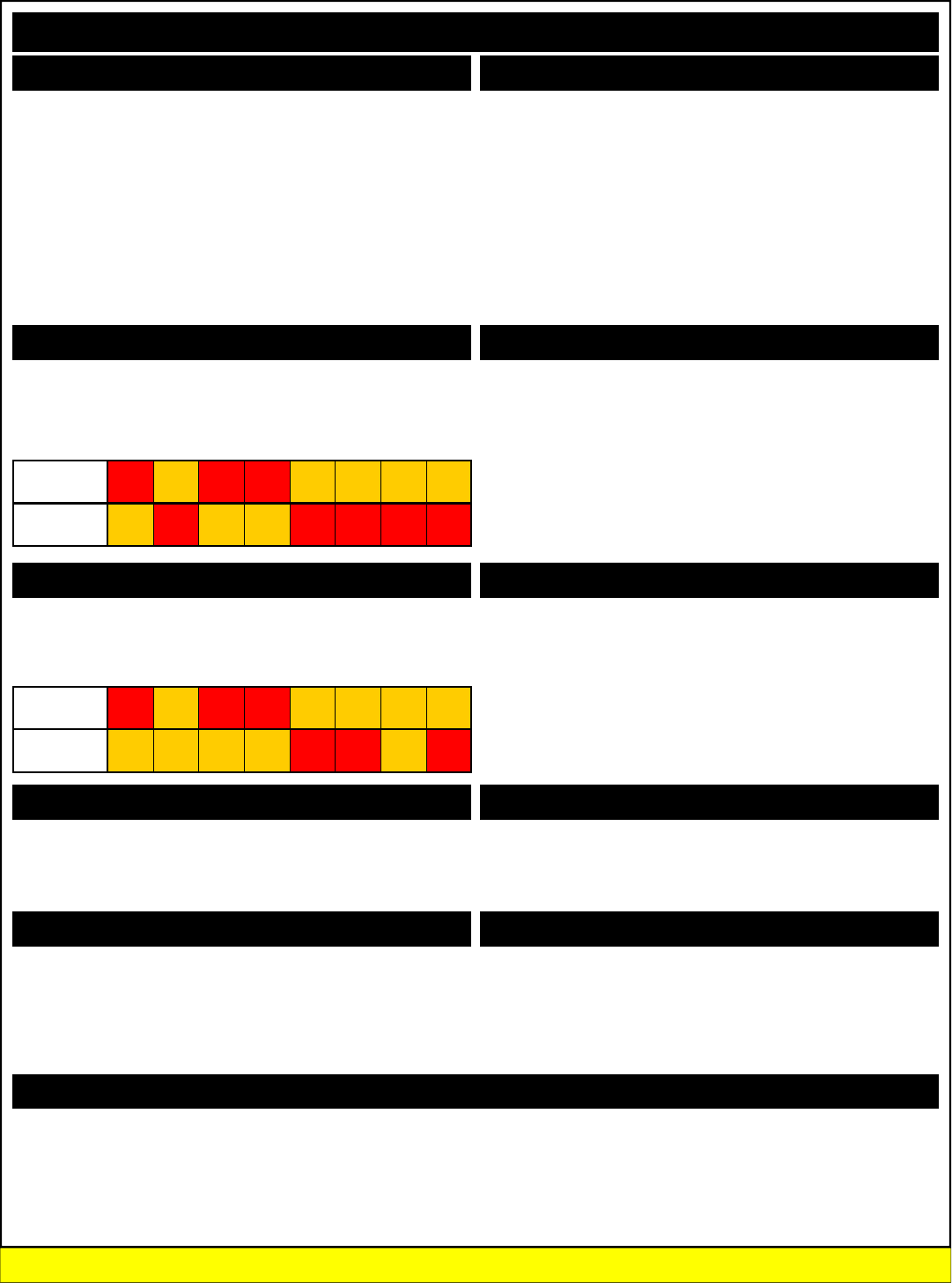
254, 31 Invert All Relays
254, 131, Bank Invert All Relays in Bank
This command is used to Invert the status of all relays. Relays that
were on turn off, relays that were off turn on. For example:
254, 32 Reverse All Relays
254, 132, Bank Reverse All Relays in Bank
This command is used to reverse the current pattern of relays in a
given relay bank. For example:
254, 33 Test 2-Way Communications with Controller
This command is used to test 2-Way communications between the PC
and the relay controller. This command does nothing except report
back an ASCII character code 85 when executed.
254, 34 Report to User the Selected Relay Bank
This command queries the relay controller and reports back the relay
bank all commands are being sent to. The importance of relay bank
selection is discussed heavily on pages 10 and 11 of this manual. You
can redirect relay control commands to a different relay bank by send-
ing 254, 49, Bank discussed later in this manual.
254,25 Turn On Automatic Relay Refreshing
254,26 Turn Off Automatic Relay Refreshing
254,35 Store Relay Refreshing Mode
254,36 Report Back Stored Refresh Settings
254,37 Manually Refresh Relay Bank
MSComm1.Output = Chr$(254) 'Enter Command Mode
MSComm1.Output = Chr$(29) 'Activate All Relays in the Selected Relay Bank
(When Reporting Mode is ON, controller will send ASCII Code 85 to Acknowledge this command)
MSComm1.Output = Chr$(254) 'Enter Command Mode
MSComm1.Output = Chr$(129) 'Activate All Relays
MSComm1.Output = Chr$(2) 'In Relay Bank 2
(When Reporting Mode is ON, controller will send ASCII Code 85 to Acknowledge this command)
MSComm1.Output = Chr$(254) 'Enter Command Mode
MSComm1.Output = Chr$(30) 'Deactivate All Relays in the Selected Relay Bank
(When Reporting Mode is ON, controller will send ASCII Code 85 to Acknowledge this command)
MSComm1.Output = Chr$(254) 'Enter Command Mode
MSComm1.Output = Chr$(130) 'Deactivate All Relays
MSComm1.Output = Chr$(2) 'In Relay Bank 2
(When Reporting Mode is ON, controller will send ASCII Code 85 to Acknowledge this command)
MSComm1.Output = Chr$(254) 'Enter Command Mode
MSComm1.Output = Chr$(31) 'Invert All Relays in the Selected Relay Bank
(When Reporting Mode is ON, controller will send ASCII Code 85 to Acknowledge this command)
MSComm1.Output = Chr$(254) 'Enter Command Mode
MSComm1.Output = Chr$(131) 'Invert All Relays
MSComm1.Output = Chr$(3) 'In Relay Bank 3
(When Reporting Mode is ON, controller will send ASCII Code 85 to Acknowledge this command)
MSComm1.Output = Chr$(254) 'Enter Command Mode
MSComm1.Output = Chr$(32) 'Reverse All Relays in the Selected Relay Bank
(When Reporting Mode is ON, controller will send ASCII Code 85 to Acknowledge this command)
MSComm1.Output = Chr$(254) 'Enter Command Mode
MSComm1.Output = Chr$(132) 'Reverse All Relays
MSComm1.Output = Chr$(3) 'In Relay Bank 3
(When Reporting Mode is ON, controller will send ASCII Code 85 to Acknowledge this command)
MSComm1.Output = Chr$(254) 'Enter Command Mode
MSComm1.Output = Chr$(33) 'Test 2-Way Communications with Relay Controller Command
(When Reporting Mode is ON, controller will send ASCII Code 85 to Acknowledge this command)
MSComm1.Output = Chr$(254) 'Enter Command Mode
MSComm1.Output = Chr$(34) 'Report Selected Relay Bank to User
(Controller will report back ASCII Character Codes 0-26, indicating which relay bank commands will
be directed to)
Relay Refreshing is discussed heavily on pages 10 and 11, and are
considered some of the most important “foundation” concepts for taking
advantage of all the features the ProXR series controllers have to offer.
Please reference these pages for detailed explanation and examples.
All Relays On/Off
Inverting Relays
Test 2-Way Communication
Reading the Currently Selected Relay Bank
Sample Code: All Relays On/Off
Sample Code: Inverting Relays
Sample Code: Reversing Relays
Sample Code: Reading Selected Relay Bank
Please Review Pages 10 and 11 to Better Understand how to Direct Commands to Different Relay Banks
Original Relay
Pattern
0
ON
1
OFF
2
ON
3
ON
4
OFF
5
OFF
6
OFF
7
OFF
Reversed
Relay Pattern
0
OFF
1
OFF
2
OFF
3
OFF
4
ON
5
ON
6
OFF
7
ON
Original Relay
Pattern
0
ON
1
OFF
2
ON
3
ON
4
OFF
5
OFF
6
OFF
7
OFF
Inverted Relay
Pattern
0
OFF
1
ON
2
OFF
3
OFF
4
ON
5
ON
6
ON
7
ON
Reversing Relays
Sample Code: Reversing Relays
Relay Refreshing Commands

254, 40, RelayData Set the Status of Relays
254, 140, RelayData, Bank Set the Status of Relays in Bank
This command writes a byte of data directly to a relay bank. This al-
lows you to easily set the status of 8 relays at one time. RelayData is a
parameter value from 0-255. A value of 0 turns off all the relays. A
value of 255 turns on all the relays. Other values set the status of the
relays in the equivalent binary pattern of the RelayData parameter
value.
NOTE: A Bank Value of 0 applies this command to all relay banks.
254, 42 Store Power Up Default Status
254, 142, Bank Store Power Up Default Status in Bank
This command stores the current status of the relays in a given bank
into memory. The next time power is applied to the controller, relays
will return to the stored on/off state. A bank value of 0 stores the pat-
tern of all relays in all 26 banks.
254, 43 Read Power Up Default Status
254, 143, Bank Read Power Up Default Status in Bank
This command reads the stored power-up default status of the relays in
a given bank. A bank value of 0 reports back 26 bytes of data, indicat-
ing the stored pattern of all 26 relay banks.
254, 49, Bank Direct Commands to Selected Relay Bank
This command is used to direct commands to a selected relay bank.
All subsequent commands will be sent to the selected relay bank. This
command only applies to commands values less than 100. Commands
in the 100+ value range allow you to specify a relay bank as part of the
command.
NOTE: Complete details on relay banking is described on Pages
10 and 11 of this manual.
There are Two helpful Routines you may want to structure into
your program that helps handle serial communications. First,
the ClearBuffer routine can be called prior to sending each
command to the relay controller, helping ensure the serial
buffer is empty and the new command is not returning old data
to your program. This has been a problem for some custom-
ers, and it is easily avoided. While this is not always neces-
sary, it should be troubleshooting starting point if the controller
seems to be sending you invalid data.
Second, the GetData routine should be used to read data from
the controller. This simple routine waits for data to arrive in the
serial buffer. Once it arrives, it grabs the data, and stores the
value in the GetData variable.
The ProXR Command Set
MSComm1.Output = Chr$(254) 'Enter Command Mode
MSComm1.Output = Chr$(40) 'Set the Status of All Relays in the Selected Relay Bank
MSComm1.Output = Chr$(170) '0-255 Valid Range, Data is Written Directly to Relay Bank
(When Reporting Mode is ON, controller will send ASCII Code 85 to Acknowledge this command)
MSComm1.Output = Chr$(254) 'Enter Command Mode
MSComm1.Output = Chr$(140) 'Set the Status of All Relays in the Selected Relay Bank
MSComm1.Output = Chr$(170) '0-255 Valid Range, Data is Written Directly to Relay Bank
MSComm1.Output = Chr$(1) 'In Relay Bank 1
(When Reporting Mode is ON, controller will send ASCII Code 85 to Acknowledge this command)
MSComm1.Output = Chr$(254) 'Enter Command Mode
MSComm1.Output = Chr$(42) 'Store Relay Settings in the Selected Relay Bank
(When Reporting Mode is ON, controller will send ASCII Code 85 to Acknowledge this command)
MSComm1.Output = Chr$(254) 'Enter Command Mode
MSComm1.Output = Chr$(142) 'Store Relay Settings
MSComm1.Output = Chr$(2) 'In Relay Bank 2
(When Reporting Mode is ON, controller will send ASCII Code 85 to Acknowledge this command)
MSComm1.Output = Chr$(254) 'Enter Command Mode
MSComm1.Output = Chr$(43) 'Read Relay Settings in the Selected Relay Bank
(Controller will report back ASCII Character Codes 0-255, Convert to Binary to See Relay Pattern)
MSComm1.Output = Chr$(254) 'Enter Command Mode
MSComm1.Output = Chr$(143) 'Read Relay Settings
MSComm1.Output = Chr$(1) 'In Relay Bank 1
(Controller will report back ASCII Character Codes 0-255, Convert to Binary to See Relay Pattern)
MSComm1.Output = Chr$(254) 'Enter Command Mode
MSComm1.Output = Chr$(49) 'Direct Relay Control Commands
MSComm1.Output = Chr$(2) 'To Relay Bank 2
(When Reporting Mode is ON, controller will send ASCII Code 85 to Acknowledge this command)
MSComm1.Output = Chr$(254) 'Enter Command Mode
MSComm1.Output = Chr$(8) 'Activate Relay 0 on Bank 2 (Bank is Selected in Above Command)
(When Reporting Mode is ON, controller will send ASCII Code 85 to Acknowledge this command)
Clearing the Serial Buffer
Public Function ClearBuffer() ‘Read a Byte of Data from the Controller in VB
While MSComm1.InBufferCount > 0 ‘If there is data in the serial port
DUMP = Asc(MSComm1.Input) 'Read Data Byte from the Serial Port
DoEvents ‘Service Other Windows Tasks (Very Important!!!)
Wend ‘Repeat the Check Again, Loop will Repeat until Empty
End Function
Reading a Byte of Data from the PC
Public Function GetData() ‘Read a Byte of Data from the Controller in VB
Do ‘Start a Continuous Loop
DoEvents ‘Service Other Windows Tasks (Very Important!!!)
Until MSComm1.InBufferCount > 0 ‘Continue Loop Until a Byte of Data is Received
GetData = ASC(MSComm1.Input) ‘Read Data Byte from the Serial Port
End Function
Set the Status of a Relay Bank
Power Up Relay Status Configuration
Sample Code: Setting Relay Bank Status
Sample Code: Relay Status on Power Up
Sample Code: Read Relay Status on Power Up
Please Review Pages 10 and 11 to Better Understand how to Direct Commands to Different Relay Banks
Read Power Up Relay Status Configuration
Changing Relay Banks Sample Code: Changing Relay Banks
Helpful Routines and Safe Programming Practices

The ProXR Series controllers have 16 user-programmable timers.
Each independent timer can be assigned to any relay, and can be pro-
grammed to hold the relay in the On state, or to pulse the relay at the
end of the timer.
The ProXR timing features are ideally suited for Watchdog, Keep Alive,
and Server Reboot applications, as well as sprinkler systems, gate
openers, and day/night lighting applications.
Relay Timing Features support two modes of operation: Duration and
Pulse. Duration timing is ideally suited for keeping a light on overnight,
watering the lawn for a given period of time, or other applications where
a device should be activated for a period of time. Pulse timing mode is
designed specifically for server reboot applications, whereby, if the
timer is not reset periodically by your software, the timer will run out and
reboot your computer.
Interactive Timing Commands
The ProXR timing commands can be used by themselves, or in con-
junction with other commands, as building blocks to create some very
sophisticated timing applications. The timing command set covers
many aspects of relay activation/deactivation, making the ProXR series
ideally suited for a broad range of timing tasks.
Limitations
The ProXR series controllers do NOT have an integrated real-time
clock. NCD Devices are not typically stand-alone. They require com-
puter interaction with the controller. Time scheduling is possible, but it
would require a program to be written on the PC to handle the sched-
ule. The timing features are suitable for applications where you may
want a light to go on for 5 minutes, or you may want to keep a relay
alive to prevent a server from automatically rebooting. The ProXR
series controllers are capable of processing timing commands as long
as 255 hours, 255 minutes, and 255 seconds (4 Days, 19 Hours, 19
Minutes, and 15 Seconds) + Deviation.
Timing Accuracy
The Accuracy of the relay timers is largely dependant on how many
timers are in use, and how much communication you do with the con-
troller while the timing commands are processing.
When a timer is already active, and you engage another timer, the du-
ration of the previously set times may be increased by as much as one
full second. You can enable all timers simultaneously if you need more
accurate timing.
Best timing accuracy is achieved by setting up your timing commands
and leaving the controller alone during the timing operations. Each
time you communicate with the controller, you will slow down the timer
(lengthening the time period the timer is set for). The more you com-
municate with the controller, the more you will slow down all timers.
Timing accuracy tends to drift over time. This timing functions built into
this controller should NOT be used if timing accuracy is critical. The
timing feature are, however, very useful in applications where a little
timing drift is not a big concern.
Timing Calibration
Timing is generically recalibrated for 60 seconds using 8 timers. Our
test controller calibration value was 26,576. In other words, a calibra-
tion value of 26,576 equals 1 second when the controller is only proc-
essing timing tasks.
The calibration value was established on our prototype and may be off
by as much as 3% based on individual resonator, processor, and tem-
perature characteristics. Baud rate was set at 115.2K when this num-
ber was established. The calibration value may need to be changed for
other baud rates, but 115.2K baud is the best choice for calibration.
You can adjust the calibration value at any time, but the calibration
value can ONLY be stored while in setup mode. If you need to commu-
nicate frequently with the controller while the timing functions are ac-
tive, you will need to decrease the calibration value. Reasonably accu-
rate timing can be achieved with some experimentation.
The ProXR Command Set: Watchdog, Keep Alive, and Server Reboot Applications
16 User-Programmable Timers
It should also be stated that you can spend a week achieving perfect
calibration for your controller, and if you were to plug the calibration
number into a different controller, it will likely not be accurate.
In addition, the timing routines built into the firmware are huge. There
are so many factors that affect timing, that even a well calibrated con-
troller will not post consistent timing scores at all timing intervals. So
you should NEVER expect to find a calibration value that works under
every circumstance. It is not possible to achieve this level of accuracy
without a real time clock. So before you waste hours finding a timing
score for your controller that works perfectly at 10 seconds or 24 hours,
then you should be warned that this is not possible.
Getting Started with Simple Timers
While all the timers in the timing commands are pretty easy to use,
simple timers are the easiest. Once you have sent a simple timer com-
mand, the timer automatically starts counting down. There are two
types of simple timers: Duration and Pulse
Simple Duration Timers
These timers activated a relay for a user specified period of time.
When the timer expires, the relay turns off. Here is an example send-
ing a simple duration timer command:
Hold Relay 0 On for 8 Hours, 10 Minutes, 15 Seconds using Simple Duration Timer 0:
MSComm1.Output = Chr$(254) 'Enter Command Mode
MSComm1.Output = Chr$(50) 'Timer Setup Command
MSComm1.Output = Chr$(50) 'Simple Duration Timer 0 Command
MSComm1.Output = Chr$(8) 'Hours (0-255)
MSComm1.Output = Chr$(10) 'Minutes (0-255)
MSComm1.Output = Chr$(15) 'Seconds (0-255)
MSComm1.Output = Chr$(0) 'Relay (0-255)
(When Reporting Mode is ON, controller will send ASCII Code 85 to Acknowledge this command)
Hold Relay 1 On for 10 Seconds using Simple Duration Timer 1:
MSComm1.Output = Chr$(254) 'Enter Command Mode
MSComm1.Output = Chr$(50) 'Timer Setup Command
MSComm1.Output = Chr$(51) 'Simple Duration Timer 0 Command
MSComm1.Output = Chr$(0) 'Hours (0-255)
MSComm1.Output = Chr$(0) 'Minutes (0-255)
MSComm1.Output = Chr$(10) 'Seconds (0-255)
MSComm1.Output = Chr$(1) 'Relay (0-255)
(When Reporting Mode is ON, controller will send ASCII Code 85 to Acknowledge this command)
When the above two commands have been sent. The heartbeat LED
on the controller will slow down. Both relays 0 and 1 will turn on. Relay
0 will turn off after 8 hours, 10 minutes, and 15 seconds. Relay 1 will
turn off after only 10 seconds. While the timers are running, you may
send other relay control commands. It is also possible to manually turn
off the relays while the timers are still running. In these cases, the tim-
ers will not appear to have any effect. You can also pause the timers
using other commands.
Keep in mind, you have 16 timers to work with. If you ever need this
many timers, it would be prudent to assign a different relay to each
timer. Assigning the same relay to 2 timers will cause the relay to turn
off when the first timer expires. The second timer will appear to have
no effect.
After the timers have expired, the heartbeat LED on the relay controller
will return to a steadily fast pace.
Also note that relays are assigned in numeric order of 0-255 when us-
ing the timing commands. Relay 0 is located on Bank 1, Relay 0. Re-
lay 8 is located on Bank 2, Relay 0. Relay 255 is located on bank 32,
Relay 7 (you will have to make use of the XR Expansion port to access
this relay).

Pulse Timers
Pulse timers are slightly different than duration timers. When a pulse
timer is activated, the relay will not do anything until the timer has ex-
pired. Once expired, the relay will turn on for 1/4th of a second. This
quarter second pulse is designed specifically to reboot a computer by
connecting a relay directly to the RESET lines of a motherboard. While
this may be used for other applications, the intent of the pulse timer is
to reboot a computer should there be a lack of communication between
the computer and the relay controller (indicative of a system crash).
Below is a simple example of setting up a pulse timer.
Pulse Relay 0 after 15 Seconds using Simple Pulse Timer 0:
MSComm1.Output = Chr$(254) 'Enter Command Mode
MSComm1.Output = Chr$(50) 'Timer Setup Command
MSComm1.Output = Chr$(70) 'Simple Pulse Timer 0 Command
MSComm1.Output = Chr$(0) 'Hours (0-255)
MSComm1.Output = Chr$(0) 'Minutes (0-255)
MSComm1.Output = Chr$(15) 'Seconds (0-255)
MSComm1.Output = Chr$(0) 'Relay (0-255)
(When Reporting Mode is ON, controller will send ASCII Code 85 to Acknowledge this command)
Pulse Relay 1 after 45 Seconds using Simple Pulse Timer 1:
MSComm1.Output = Chr$(254) 'Enter Command Mode
MSComm1.Output = Chr$(50) 'Timer Setup Command
MSComm1.Output = Chr$(71) 'Simple Pulse Timer 0 Command
MSComm1.Output = Chr$(0) 'Hours (0-255)
MSComm1.Output = Chr$(0) 'Minutes (0-255)
MSComm1.Output = Chr$(45) 'Seconds (0-255)
MSComm1.Output = Chr$(1) 'Relay (0-255)
(When Reporting Mode is ON, controller will send ASCII Code 85 to Acknowledge this command)
In the examples above, Relay 0 will pulse after 15 seconds and Relay 1
will pulse after 45 seconds.
Mixing Duration and Pulse Timers
You can mix duration and pulse timers as your application requires, in
any combination. Care should be taken not to mix timers. For exam-
ple, on the previous page, we utilized timers 0 and 1 using the com-
mands 50 and 51. On this page, we utilized timers 0 and 1 using the
commands 70 and 71. The commands 50 and 70 both use timer 0.
Likewise, the commands 51 and 71 use timer 1. Here is a simple over-
lap map that will help you keep track of what commands address spe-
cific timers. The table below shows the beginning command bytes:
*These timers do not automatically activate, they must be started using
a different command. More on this a little later in the manual.
The ProXR Command Set: Watchdog, Keep Alive, and Server Reboot Applications
Server Reboot Pulse Timers
Server Reboot Methodology
You can call it a watchdog timer, a keep-alive timer, or a server reboot
timer. They can all mean about the same thing, as their goals are basi-
cally the same. The idea is simple: If the computer crashes, the com-
puter cannot reset the timer built into the ProXR controller, so the con-
troller reboots the computer. Implementation is not too difficult.
Implementing a Server Reboot Strategy for a Single Computer
A Server reboot system can work many ways. One possible strategy is
a system whereby a server would boot up with a ProXR relay controller
attached to the serial port. The relay controller would also be con-
nected to the reset lines of server motherboard. As part of the startup
items, a program would be launched to activate the pulse timer function
for a period of 10 minutes (for example). The relay would do nothing
since a pulse timer is used. Using this strategy, the relay controller
would reboot the computer if communications is lost between the server
and the relay controller. Once the timer in the relay controller has ex-
pired, it can only be restarted when the computer boots up normally.
The monitoring program could be exited at any time. In which case, all
timers would be cleared to prevent rebooting the computer.
Implementing a Server Reboot Strategy in a Network
The strategy above could be implemented on a single computer with an
enhanced version of the software. The relay controller could be tied
into the reset lines on the other computers as well. The program could
be enhanced to “ping” other computers on the network. If one of them
should fail to respond to your “ping”, a command could be sent to re-
boot the computer that failed to respond. In this case, one computer (a
main server) is protected, as well as all other computers on the net-
work. The main server is acting as the watchdog for all the other com-
puters on the network. The relay controller itself is acting as the watch-
dog for the main server computer.
While there are many other strategies that could be easily imple-
mented, these strategies could perhaps serve as building blocks to
greater, more powerful and sophisticated watchdog monitoring applica-
tions.
Timer
Number
Duration
Timer
Pulse
Timer
Duration
Timer*
Pulse
Timer*
0 254, 50, 50 254, 50, 70 254, 50, 90 254, 50, 110
1 254, 50, 51 254, 50, 71 254, 50, 91 254, 50, 111
2 254, 50, 52 254, 50, 72 254, 50, 92 254, 50, 112
3 254, 50, 53 254, 50, 73 254, 50, 93 254, 50, 113
4 254, 50, 54 254, 50, 74 254, 50, 94 254, 50, 114
5 254, 50, 55 254, 50, 75 254, 50, 95 254, 50, 115
6 254, 50, 56 254, 50, 76 254, 50, 96 254, 50, 116
7 254, 50, 57 254, 50, 77 254, 50, 97 254, 50, 117
8 254, 50, 58 254, 50, 78 254, 50, 98 254, 50, 118
9 254, 50, 59 254, 50, 79 254, 50, 99 254, 50, 119
10 254, 50, 60 254, 50, 80 254, 50, 100 254, 50, 120
11 254, 50, 61 254, 50, 81 254, 50, 101 254, 50, 121
12 254, 50, 62 254, 50, 82 254, 50, 102 254, 50, 122
13 254, 50, 63 254, 50, 83 254, 50, 103 254, 50, 123
14 254, 50, 64 254, 50, 84 254, 50, 104 254, 50, 124
15 254, 50, 65 254, 50, 85 254, 50, 105 254, 50, 125

More timer Commands?
To this point, we have discussed simple timers. These timers begin
operation as soon as the command is received. This makes them easy
to use, but also imposes a few restrictions in that timers cannot be syn-
chronized perfectly with each other. So we decided to provide our us-
ers with a command set that allows you to define the times without
initiating the timer. Instead, the timing data for all 16 timers are stored
in temporary memory until they are initiated. The following commands
store timing data, but do not trigger the countdown. You will use a
different command to control which timers are counting down and which
timers are “stalled”.
Setup a Pulse Timer on Relay 0 for 15 Seconds using Timer 0:
MSComm1.Output = Chr$(254) 'Enter Command Mode
MSComm1.Output = Chr$(50) 'Timer Setup Command
MSComm1.Output = Chr$(110) 'Pulse Timer 0 Setup Command
MSComm1.Output = Chr$(0) 'Hours (0-255)
MSComm1.Output = Chr$(0) 'Minutes (0-255)
MSComm1.Output = Chr$(15) 'Seconds (0-255)
MSComm1.Output = Chr$(0) 'Relay (0-255)
(When Reporting Mode is ON, controller will send ASCII Code 85 to Acknowledge this command)
Setup a Duration Timer on Relay 1 for 35 Seconds using Timer 1:
MSComm1.Output = Chr$(254) 'Enter Command Mode
MSComm1.Output = Chr$(50) 'Timer Setup Command
MSComm1.Output = Chr$(91) 'Duration Timer 1 Setup Command
MSComm1.Output = Chr$(0) 'Hours (0-255)
MSComm1.Output = Chr$(0) 'Minutes (0-255)
MSComm1.Output = Chr$(35) 'Seconds (0-255)
MSComm1.Output = Chr$(1) 'Relay (0-255)
(When Reporting Mode is ON, controller will send ASCII Code 85 to Acknowledge this command)
In the examples above, two timers will be setup, but they will not start
counting down until they are activated. Timers are activated using a
separate command:
Begin Countdown of Timers 0 and 1:
LSB = 3 ‘1 + 2 = 3 1 is for Timer 0, 2 is for Timer 2, See Table Below
MSB = 0 ‘Keep all other timers off
MSComm1.Output = Chr$(254) 'Enter Command Mode
MSComm1.Output = Chr$(50) 'Timer Setup Command
MSComm1.Output = Chr$(131) 'Control Active and Halted Timers Command
MSComm1.Output = Chr$(LSB) '16-Bit Value, Least Significant Byte
MSComm1.Output = Chr$(MSB) '16-Bit Value, Most Significant Byte
(When Reporting Mode is ON, controller will send ASCII Code 85 to Acknowledge this command)
If you understand how binary works, this is a pretty simple command.
A 16 bit value is used to control which timers are active and which tim-
ers are halted. Each of the 16 bits identifies with each of the 16 timers.
A binary 0 in any bit location indicates the timer is off while a binary 1 in
any bit location indicates the timer is on. If you are not familiar with
binary, here is a crash course:
16 Timers have 16 Bits, but we have to divide these into two 8-Bit val-
ues to communicate these data via a serial port. We call these two
different bytes LSB for Least Significant Byte and MSB for Most Signifi-
cant Byte. Follow the section below to figure LSB and MSB Values:
Timer 0 has a value of 1 on the LSB Timer 8 has a value of 1 on the MSB
Timer 1 has a value of 2 on the LSB Timer 9 has a value of 2 on the MSB
Timer 2 has a value of 4 on the LSB Timer 10 has a value of 4 on the MSB
Timer 3 has a value of 8 on the LSB Timer 11 has a value of 8 on the MSB
Timer 4 has a value of 16 on the LSB Timer 12 has a value of 16 on the MSB
Timer 5 has a value of 32 on the LSB Timer 13 has a value of 32 on the MSB
Timer 6 has a value of 64 on the LSB Timer 14 has a value of 64 on the MSB
Timer 7 has a value of 128 on the LSB Timer 15 has a value of 128 on the MSB
To Turn On timers, add up the LSB and MSB Values. For example:
To turn on timers 0, 1, 2, and 3 we add up 1, 2, 4, and 8.
So the LSB = 15.
To turn on timers 10, 12, 14, and 15, we add up 4, 16, 64, and 128.
So the MSB = 212.
After you send the LSB and MSB timer data to the controller, the se-
lected timers will be activated. All other timers will be halted.
The ProXR Command Set: Watchdog, Keep Alive, and Server Reboot Applications
Advanced Timer Commands
Timer Query
The Timer Query command is used to view the current status of any
timer. All timers are countdown in nature. Timer Query allows you to
see how much time remains before the timer expires. The example
below illustrates the use the Timer Query command:
MSComm1.Output = Chr$(254) 'Enter Command Mode
MSComm1.Output = Chr$(50) 'Timer Setup Command
MSComm1.Output = Chr$(130) 'Issue Timer Query Command
MSComm1.Output = Chr$(0) 'Select a Timer to Query (0-15)
The first byte sent back to the PC will contain the number of hours left on the selected timer.
The second byte sent back to the PC will contain the number of minutes left on the selected timer.
The third byte sent back to the PC will contain the number of seconds left on the selected timer.
The fourth byte sent back to the PC will contain the relay number the timer applies to (0-255).
Setting the Timer Calibration Value
As discussed earlier in the manual, you can calibrate the timer at any
time. If the controller is in Configuration mode (all dip switches off),
calibration data will be stored when this command is issued. Other-
wise, the calibration value will be changed, but settings will be lost
when power is cycled.
Calibrator = 26576 ‘26575 Counts Equals 1 Second
LSB = (Calibrator And 255) ‘Compute the LSB Value of the Calibrator
MSB = (Calibrator And 65280) / 256 ‘Compute the MSB Value of the Calibrator
MSComm1.Output = Chr$(254) 'Enter Command Mode
MSComm1.Output = Chr$(50) 'Timer Setup Command
MSComm1.Output = Chr$(132) 'Issue the Set Calibrator Command
MSComm1.Output = Chr$(LSB) 'Send Calibrator LSB Value (0-255)
MSComm1.Output = Chr$(MSB) 'Send Calibrator MSB Value (0-255)
(When Reporting Mode is ON, controller will send ASCII Code 85 to Acknowledge this command)
Reading the Timer Calibration Value
You may also read the calibration value stored in the controller by issu-
ing the Calibrator Read command. This command returns two bytes of
data to the user.
MSComm1.Output = Chr$(254) 'Enter Command Mode
MSComm1.Output = Chr$(50) 'Timer Setup Command
MSComm1.Output = Chr$(133) 'Issue the Set Calibrator Command
The first byte sent back to the PC will contain the Timer Calibrator LSB Value
The second byte sent back to the PC will contain the Timer Calibrator MSB Value
Calibrator = (LSB + (MSB * 256)) ‘This math function “rebuilds” the calibration value
Activating Calibrator Markers
Time calibrator markers are used to help calibrate the timer. When the
calibrator markers have been activated, the controller will send our
ASCII character code 90 at the beginning of any timing event. ASCII
character code 91 will be sent at the end of any timing event. The time
measured between the receiving 90 and 91 is used to help the user set
the calibration value. These markers may prove useful if you need your
PC to know when a timing even has occurred.
MSComm1.Output = Chr$(254) 'Enter Command Mode
MSComm1.Output = Chr$(50) 'Timer Setup Command
MSComm1.Output = Chr$(134) 'Issue the Set Calibrator Command
(When Reporting Mode is ON, controller will send ASCII Code 85 to Acknowledge this command)
Deactivating Calibrator Markers
This command turns off the calibration markers described above.
MSComm1.Output = Chr$(254) 'Enter Command Mode
MSComm1.Output = Chr$(50) 'Timer Setup Command
MSComm1.Output = Chr$(135) 'Issue the Set Calibrator Command
(When Reporting Mode is ON, controller will send ASCII Code 85 to Acknowledge this command)

Fighting Electromagnetic Interference (EMI)
Any relay controller has to consider EMI as a possible mechanism that
can cause serious interference with normal operation. In extreme
cases, EMI can cause the relays in a given relay bank to turn off, or
even reboot the ProXR processor. We have taken several steps to
help reduce EMI absorption on the logic side of the controller. How-
ever, there are some conditions that MAY still exist whereby EMI will
cause all relays on a given bank to turn off.
When relay status information is sent from the controller to the relay
bank, data is normally sent only one time. But the possibility does exist
that the relay is turning on a device that generates a tremendous
amount of EMI. Most of these kinds of devices, such as large DC mo-
tors, generate most of their EMI when power is first applied. During this
time (the initial startup of the motor), huge amounts of EMI must be
absorbed by the relays and inducted back onto the logic of the control-
ler. It is during this time the controller becomes the most vulnerable to
EMI absorption.
It is for this reason we have introduced the Repetitions (Reps) com-
mand. The Reps command is used to tell the controller to send relay
control data Repeatedly to the relay banks. The theory is that motor
will be fighting to turn on, generating EMI that can clear the relay logic
circuits...but the controller can now fight back by telling the relay bank
to go back on again.
Reps has been introduced as an experimental command, in hopes that
we would have a solution for this problem should it ever arise for our
customers. We would greatly appreciate any feedback our customers
would be willing to provide on the usefulness of the Reps command.
The value specified by the Reps command controls how many times
relay status data is sent to the Relay control chips. Normally, Reps is
set to a value of 1. But if you experience relays that turn themselves off
when activated, try changing the Reps value to any number from 2 to
255 and see what happens. It takes more than a second to process
each relay control command when Reps is set to 255.
Note: If the controller is in configuration mode, the Reps value will be
stored in Non-Volatile EEPROM. Otherwise, the Reps value will be lost
any time the controller is power cycled.
Set the Reps Value
MSComm1.Output = Chr$(254) 'Enter Command Mode
MSComm1.Output = Chr$(50) 'Timer and Setup Commands
MSComm1.Output = Chr$(137) 'Set the Reps Value
MSComm1.Output = Chr$(128) 'Reps(1-255) How Many Times Relays are Refreshed
(When Reporting Mode is ON, controller will send ASCII Code 85 to Acknowledge this command)
This command reports back to the user the current Reps value.
Read the Reps Value
MSComm1.Output = Chr$(254) 'Enter Command Mode
MSComm1.Output = Chr$(50) 'Timer and Setup Commands
MSComm1.Output = Chr$(136) 'Read the Reps Value Command
The Controller will Report Back the Current Reps Value
Safe Parameters
Another “just-in-case” feature we have included in the ProXR firmware
is a command that sets all the key variables inside the controller to Safe
Parameters. If for some reason, the controller does not seem be func-
tioning properly, or it appears you have lost communication, try sending
this command and see if it recovers. We have never needed this com-
mand, but just in case it proves to be useful under highly unusual cir-
cumstances...we thought we would throw it in anyway.
Recovery Attempt to Safe Parameters
MSComm1.Output = Chr$(254) 'Enter Command Mode
MSComm1.Output = Chr$(50) 'Timer and Setup Commands
MSComm1.Output = Chr$(147) 'Setup Safe Parameters
(When Reporting Mode is ON, controller will send ASCII Code 85 to Acknowledge this command)
The ProXR Command Set: Advanced Configuration Command Set
Advanced Configuration Commands
Setting the Character Delay Value
The Character Delay value determines the spacing between data bytes
sent from the controller back to your PC. By default, CDEL is set to 35,
which is known to be a conservatively safe value. The minimum allows
CDEL value is 3 (we have not seen a PC that can handle this setting).
If you want to boost performance, set the CDEL lower. A value of 7-10
should provide greatly improved communication speed.
Note: This command stores the CDEL value into Non-Volatile
EEPROM while in configuration mode only. The CDEL value will have
no effect in configuration mode (CDEL is ALWAYS 35 in configuration
mode to ensure safe communications). This command is only proc-
essed in configuration mode, it is ignored in runtime mode. In runtime
mode, you will receive ASCII character code 85 if this command is
issued.
MSComm1.Output = Chr$(254) 'Enter Command Mode
MSComm1.Output = Chr$(50) 'Timer and Setup Commands
MSComm1.Output = Chr$(139) 'Set the CDEL Value of the Controller in Runtime Mode
MSComm1.Output = Chr$(10) 'Improve Communication Speed in Runtime Mode
(When Reporting Mode is ON, controller will send ASCII Code 85 to Acknowledge this command)
Reading the Character Delay Value
This command reads the stored character delay value from the control-
ler. This command returns a value from 3 to 255.
MSComm1.Output = Chr$(254) 'Enter Command Mode
MSComm1.Output = Chr$(50) 'Timer Setup Command
MSComm1.Output = Chr$(138) 'Read the CDEL Value from the Controller Command
The controller will report back a byte of data from 3 to 255 indicating the Character Delay value.
Setting the Attached Banks Value
The ProXR series controllers are shipped as though the customer has
256 relays attached. This allows the controller to be instantly compati-
ble with several XR expansion boards, right out of the box. However,
you can gain a performance increase by setting the Attached Banks
value to the actual number of relays you are using. If you are using a
16 Relay ProXR controller, and you reduce the Attached Banks value to
2, relay control operations will be processed 16 times faster. If you
have a 32 relay controller and you reduce the Attached Banks value to
4, relay control operations will be processed 8 times faster. To deter-
mine the appropriate Attached Banks value, divide the number of total
relays you will be using by 8. Valid attached bank values are 1 to 32.
Warning: It is not possible to control relays beyond the Attached Value.
Extra relays will appear to mirror previous banks and will not be directly
controllable. If you experience any problems communicating to extra
relay banks, the Attached Banks value should be checked. This Com-
mand ONLY Works in Configuration Mode.
MSComm1.Output = Chr$(254) 'Enter Command Mode
MSComm1.Output = Chr$(50) 'Timer and Setup Commands
MSComm1.Output = Chr$(141) 'Set Attached Banks Command
MSComm1.Output = Chr$(4) 'Controller Processes 4 Banks of 8 Relays (32 Relays)
(When Reporting Mode is ON, controller will send ASCII Code 85 to Acknowledge this command)
Reading the Attached Banks Value
This command reports back a value from 1 to 32, indicating how many
relays are attached to the relay controller. Note that this number is
always set by the user. By default, this command return a value of 32.
You can gain a performance increase by reducing the Attached Banks
value. See Above: Setting the Attached Banks Value
MSComm1.Output = Chr$(254) 'Enter Command Mode
MSComm1.Output = Chr$(50) 'Timer and Setup Commands
MSComm1.Output = Chr$(140) 'Read the Attached Banks Value
This Command Reports Back a Value of 1 to 32, Indicating the Number of Relay Banks Attached to
the ProXR Series controller. By default, this command will report back 32.

Setting the Test Cycle Value
When the ProXR series controllers are powered up in Configuration
mode (all dip switches in the off position), the first instruction the con-
troller processes is a function that tests all the on board relays. By
default, the ProXR controller will test 4 banks of relays, which is the
maximum number of relays that we currently product on a single circuit
board. If you have a controller with fewer relays, you will speed up the
test cycle by setting the controller to the actual number of relay banks
on your ProXR controller. Valid Test Cycle values range from 0 to 32,
allowing the controller to test all 256 relays (32 banks of 8). A Test
Cycle value of 0 turns off automatic relay testing in configuration mode.
Since this is a relatively harmless setting, this command works in
both configuration and runtime modes.
Warning: We strongly encourage customers NOT to use configuration
mode for daily use. As a reminder that the controller is in configuration
mode, we recommend leaving the Test Cycle value to 1 or more.
When the controller is in configuration mode, internal memory is not
protected, and is fully changeable at any time. Runtime mode (and dip
switch setting other than all switches in the off position) protects internal
memory from accidental modification.
Warning: The ProXR controller will appear to lock up if the Test Cycle
value is set greater than the total number of available relay banks.
Rest assured, the controller has NOT locked up, it is testing extended
banks. Leave the controller on for several seconds and the heartbeat
LED will begin flashing.
MSComm1.Output = Chr$(254) 'Enter Command Mode
MSComm1.Output = Chr$(50) 'Timer and Setup Commands
MSComm1.Output = Chr$(146) 'Set the Test Cycle Value
MSComm1.Output = Chr$(4) 'Controller Tests 4 Banks of 8 Relays (32 Relays)
(When Reporting Mode is ON, controller will send ASCII Code 85 to Acknowledge this command)
Reading the Test Cycle Value
This command reports back a value from 0 to 32, indicating how many
relays are tested when the controller is powered up in configuration
mode (all dip switches in the off position). Note that this number is
always set by the user. By default, this command return a value of 4.
You can gain a performance increase by reducing the Test Cycle
Banks value. See Above: Setting the Test Cycle Banks Value
MSComm1.Output = Chr$(254) 'Enter Command Mode
MSComm1.Output = Chr$(50) 'Timer and Setup Commands
MSComm1.Output = Chr$(145) 'Read the Attached Banks Value
This Command Reports Back a Value of 0 to 32, Indicating the Number of Relay Banks Tested
when the ProXR Series controller is in configuration mode. By default, this command will report
back 4.
Restoring Factory Default Settings
This command operates in configuration mode only (all dip switches in
the off position). This command restores many internal parameters to
the factory default settings. See below for a detailed list:
E3C Device Number is Set to 0
Auto Refresh is Activated
Default Timing is Set to 26,576
Relay Command Repetitions is Set to 1
Character Delay is Set to 35
Reporting Mode is Turned On
Attached Relay Banks is Set to 32
MSComm1.Output = Chr$(254) 'Enter Command Mode
MSComm1.Output = Chr$(50) 'Timer and Setup Commands
MSComm1.Output = Chr$(144) 'Restore Factory Default Settings
When Reporting Mode is ON, controller will send ASCII Code 85 to Acknowledge this command)
Command Set Conclusion
This concludes the user command set for the ProXR series controllers.
The processor core is 97% full of code. This is our largest relay control
core we have ever developed. Should you discover any bugs, please
do not hesitate to contact Ryan Sheldon ryan@controlanything.com.
The ProXR Command Set: Advanced Configuration Command Set
Advanced Configuration Commands
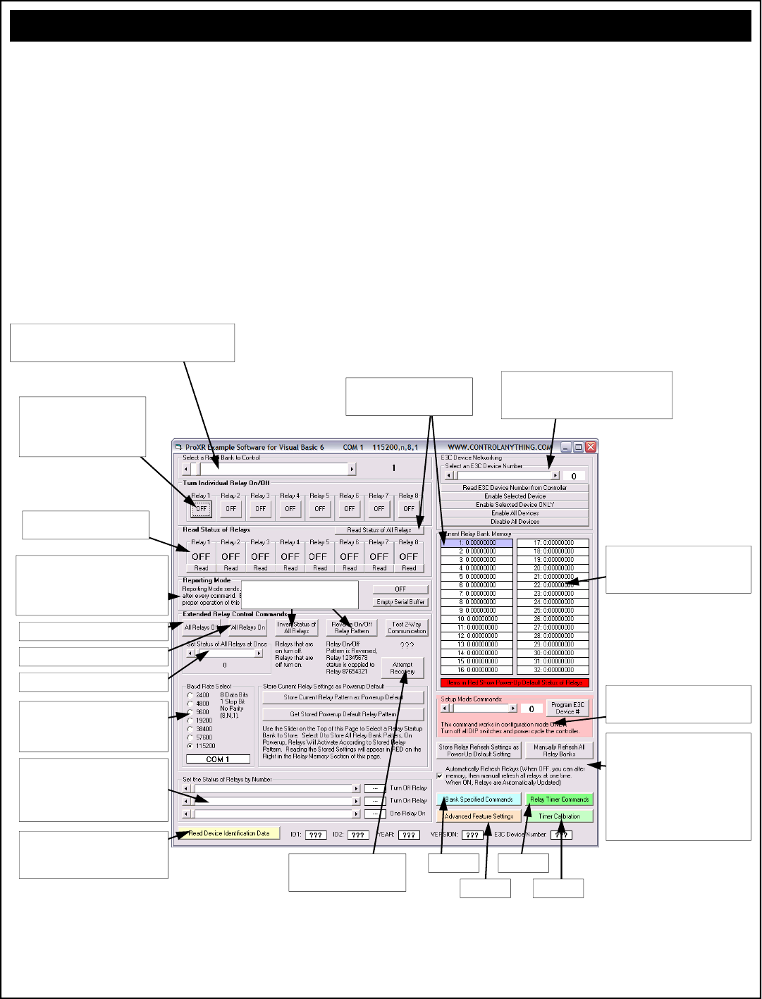
Installing and Running the ProXR Software
For your convenience, we have developed software that will test all the
functions the ProXR series controllers have to offer. This application is
available for free download from our web site at
www.controlanything.com. This program was developed using Visual
Basic 6 Professional on a Windows XP Professional computer. The
compatibility with XP Home and other versions of Windows have NOT
been tested. If you experience installation problems, please be aware
that we may not be able to help. The installation is created by Visual
Basic, we did not develop the install program. It should also be stated
that the GUI is NOT required to use ProXR series controllers. While it
is convenient and can help you change controller settings and configu-
rations quickly, it is in no way critical to the operation of a ProXR con-
troller. Keep in mind, ProXR controllers are simple devices that simply
wait for your commands. ProXR controllers do not care what is gener-
ating the commands, only that the data is valid. We have fully docu-
mented the command set to this point. Weather you choose to use our
GUI or develop your own, we have provided all the necessary informa-
tion for you to get started. The next few pages will document our GUI
to help get you better acquainted.
The ProXR Graphical User Interface (GUI)
Select a Relay Bank to Control using this Slider, All Relay Control
Commands will be Directed to the Selected Relay Bank. Setting this
Slider to 0 will send your relay control commands to ALL Relay Banks.
Set the Status of Individual relays
using these buttons. Keep in mind,
Banks are used to speak to groups of
8 relays, but it is possible to send
commands to all relays as well.
Read the Status of All Relays. Status
will be Displayed in the Current Relay
Bank Memory section.
Read the Status of Individual Relays
in a Selected Bank by Clicking Here.
Reporting Mode sends an ASCII Character
Code 85 Back to the PC after the Command
has Processed. We STRONGLY recommend
using Reporting Mode and 2-Way communica-
tion with ProXR Series controllers.
Activates All Relays in the Selected Bank.
Turns All Relays in the Selected Bank Off.
Sets Relay Status in Binary Patterns
This program automatically determines the
communication baud rate when the controller
is properly connected to a serial port. You
can manually change baud rates at any time.
These commands allow you to activate/
deactivate relays using their numeric value
instead of using the Bank and Relay number-
ing system. Relays are address by values
from 0 to 255 instead.
This Button Reads Device Identification Data
from the Controller, this is a new feature that
will be supported in all products we manufac-
ture from 2006 onward.
Some Alternate Commands for
Quickly Changing Relay Status:
The E3C Command Set allows you control up to 256
different NCD Devices on a Single Serial Port.
These commands are used to control which devices
will Respond to and ignore your commands.
This window shows the status of all relays at
one time. You may need to manually
refresh this window, not all commands will
automatically update.
Program the E3C device number, ProXR
must be in configuration mode for this
command to work.
Just in case things go wrong...see
if this command will make them
right again...
Manual and Automatic Refreshing are very
powerful commands. Turn off automatic
refreshing, use all the regular relay control
commands to alter the memory of the
ProXR controller. The relays will NOT
responds when automatic refreshing is off.
Once you have set the status of all memory
banks, you can manually refresh the relays.
This allows you to easily control the status
of all relays at one time.
See page 21.
See page 24.
See page 22.
See page 23.
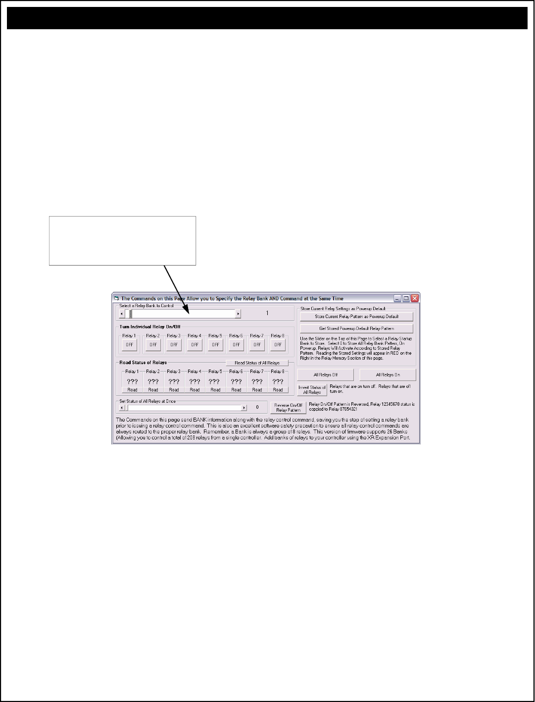
Sending Commands Directly to a Relay Bank
The commands on this window are used to address a specific relay
bank. They may not look different than some of the other commands
you have seen, but there is a distinctive difference in how they commu-
nicated relay control data to the controller.
Up until this point, you would use a separate command to specify a
relay bank. All subsequent relay control commands will be directed to
the bank. This method separates “Bank Specification” and relay control
commands from each other. Meaning you use a command to specify a
relay bank, you use another command for relay control.
The commands in this GUI specify a relay bank as part of the com-
mand. These commands should be considered more reliable because
they will function properly if the controller has been power cycled. But
they are slightly slower to process. Each command below transmits the
Bank as a part of the command, ensuring commands are always di-
rected to the correct relay.
The ProXR Graphical User Interface (GUI)
Unlike the Bank Selector on the Previous page, this slider does
NOT send any data to the controller. Instead, every button on
this page reads this slider and sends out the slider setting as part
of the command structure. This is slightly slower, but there is no
chance of accidentally activating the wrong relay because of a
power failure to the ProXR controller.
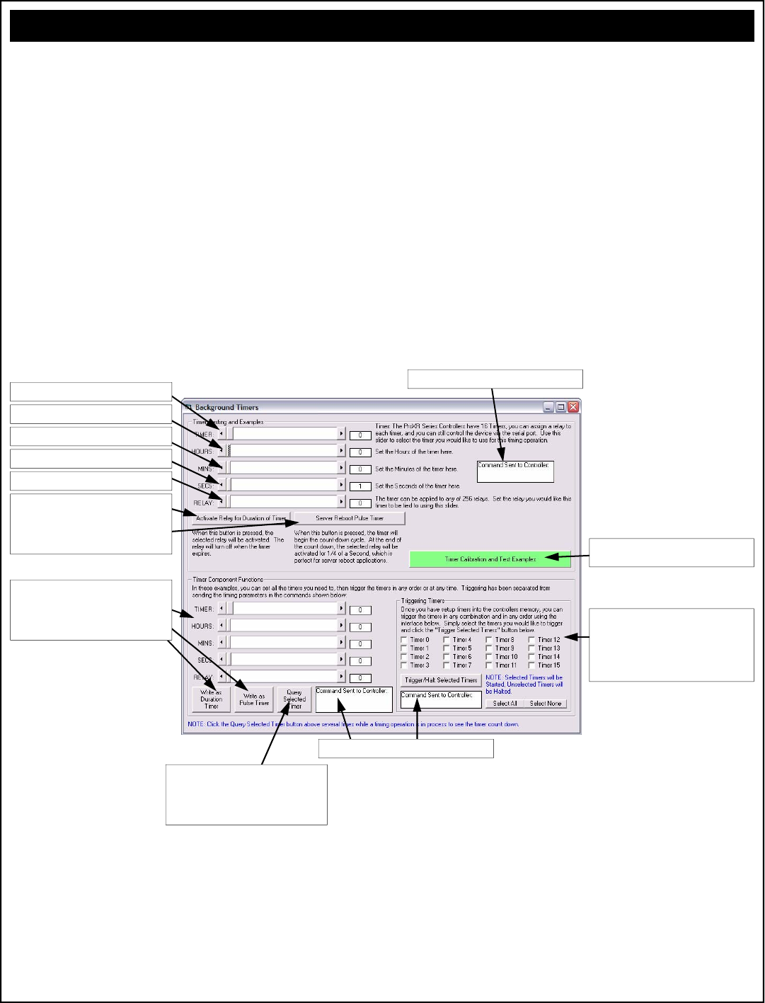
Timer Commands
This GUI demonstrates the powerful timing commands the ProXR se-
ries controllers have to offer. The ProXR series controllers have 16
timers, ideal for watchdog, keep alive, and server reboot timing applica-
tions. ProXR controllers are also an ideal choice for duration timing
applications, such as activating a light for 8 hours, or watering a lawn
for 30 minutes. Additional timer commands allow you to monitor the
current time remaining on each of the 16 timers, as well as halt/start
timers in any order. The commands on this GUI have been enhanced
with three white boxes that allow you to see what commands are actu-
ally being sent to the controller.
The ProXR Graphical User Interface (GUI)
Step 1: Choose a Timer, there are 16 Available
Step 6: Activate the Timer as a Duration or a
Pulse Timer. Duration timers keep a relay on
throughout the time cycle. Pulse timer pulse a
relay for 1/4 of a second at the end of the time
cycle (designed for server reboot applications).
Step 2: How Many Hours till Timer Expires
Step 3: How Many Minutes till Timer Expires
Step 4: How Many Seconds till Timer Expires
Step 5: Which Relay will this Timer Control
These commands do the exact same thing as
above, except they are used to store the timer
setup information ONLY. Timers are NOT
automatically triggered when these commands
are used.
See the data sent to the ProXR Controller in this box.
You can Query any of the 16 timers to see how
much time is remaining. The sliders will be
adjusted every time this button is pushed when
an active timer is queried.
See the data sent to the ProXR Controller in this box.
This interface allows you to Start or Halt ANY of
the timers at any time. This is ideal if you want to
cancel a timer event. Click the check boxes for
the timers you would like active...all others will be
halted. Then click the “Trigger/Halt Selected
Timers” button.
You can calibrate the accuracy of the timer with
this button. See page 23 for more details.
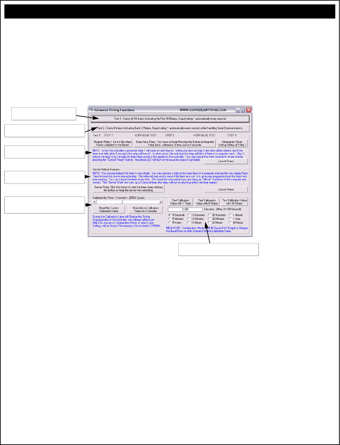
Advanced Timer Calibration Features Test
This GUI serves the purpose of demonstrating how the timers can be
used in watchdog, keep alive, and server reboot timing applications.
These commands are self explanatory for the most part.
The ProXR Graphical User Interface (GUI)
Assigns 16 Timers to 16 Relays...watch
them count down 1 second at a time….
Demonstrates how the controller is capable of handling
timing and RS-232 commands at the same time.
Follow these instructions to demonstrate the implemen-
tation of a simple Keep Alive timer.
A Server Reboot Timer is very useful for protecting
against computer crashes.
Use these controls to calibrate the timing of the
controller. This is very useful if you plan to do a lot of
serial communications along with background timers.
Several tools are provided to help you calibrate the
timer for best possible accuracy.
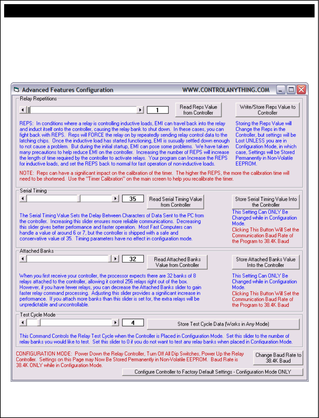
Advanced Configuration Features
We have provided lots of notes directly on the Advanced Features Con-
figuration screen. The ProXR controller should be in configuration
mode (all dip switches in the off position) before these setting will be
stored permanently in non-volatile EEPROM. Some settings can be
changed during regular runtime operation, but they will not be stored.
Please see the notes below for each of the different controls.
The ProXR Graphical User Interface (GUI)
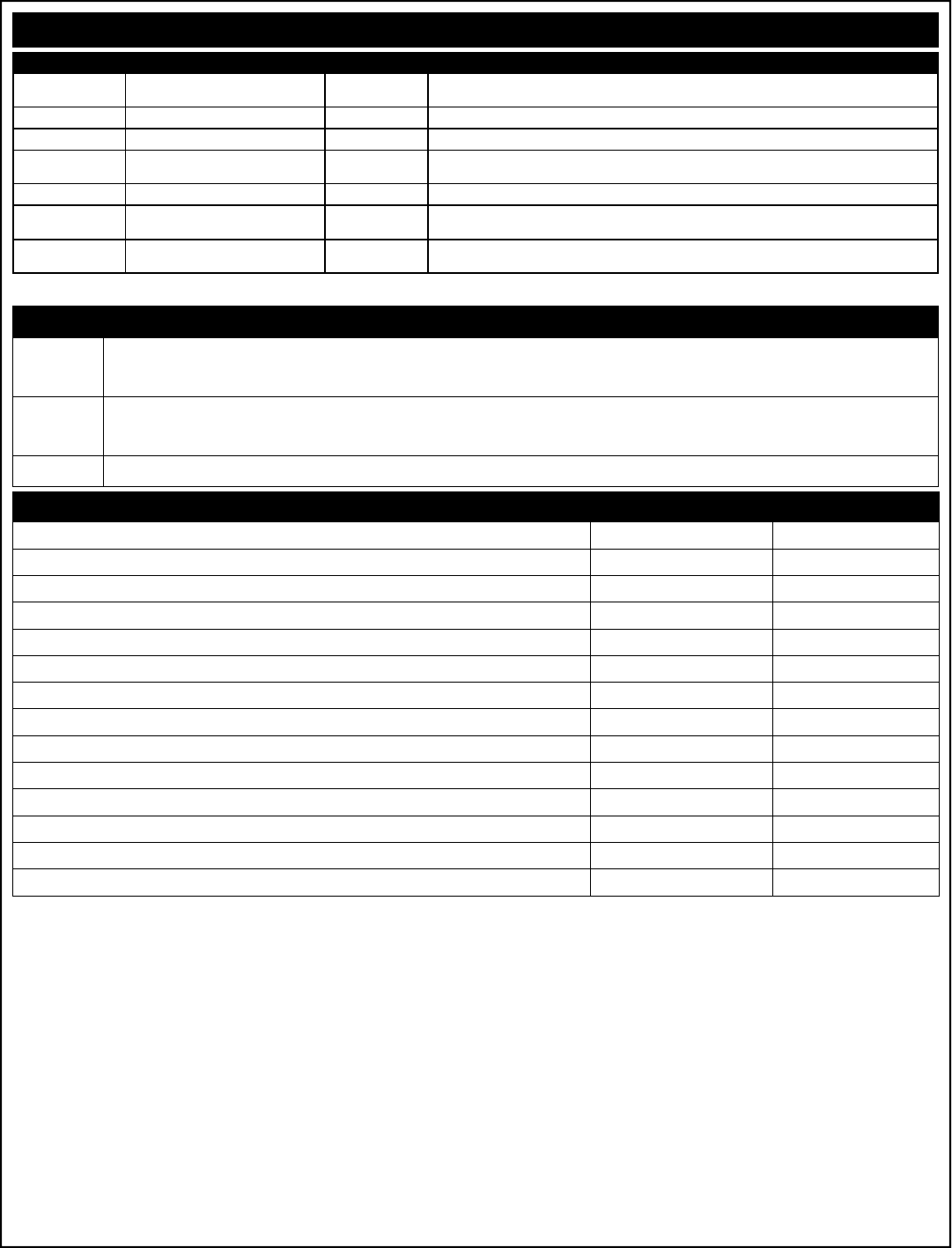
Electrical Ratings and Switching Characteristics
Characteristics Data Minimum Maximum
Relay Activation Time >5 ms <15 ms
Relay Deactivation Time >5 ms <20 ms
Activations per Second at 9600 Baud using “ProXR” Command Set N/A 480
Activations per Second at 115.2K Baud using “ProXR” Command Set (Bank Pre-Selected) N/A 5760
Activations per Second at 115.2K Baud using “ProXR” Command Set (Bank Specified) N/A 3840
Communication Distance from PC Without Boosting Signal 1200 Baud* N/A Aprox. 2000 Feet
Communication Distance from PC Without Boosting Signal 2400 Baud* N/A Aprox. 1200 Feet
Communication Distance from PC Without Boosting Signal 9600 Baud* N/A Aprox. 600 Feet
Communication Distance from PC Without Boosting Signal 19.2K Baud* N/A Aprox. 200 Feet
Communication Distance from PC Without Boosting Signal 115.2K Baud* N/A Aprox. 10 Feet
Maximum Allowed Activation Time per Relay (Relay Held in On State) N/A Unlimited
Expected Operational Life, Non-DPDT Models >10,000,000 Cycles N/A
Expected Operational Life, DPDT Models >2,000,000 Cycles N/A
Typical Operational Cycles Per Minute N/A 1,800
* assumes good quality low-capacitive wire, twisted pair preferred. Note that distances are estimated. Typically, longer distances are easily achieved.
All ratings above are for Resistive Loads. Divide current switching capabilities by 2 for Inductive Loads. Inductive loads not recommended for 1A DPDT relay controller models.
Model Ratings Relay Type Notes
1A DPDT 3A 120VAC / 3A 20VDC DPDT DPDT: Two Switches per Relay
Not for use with Inductive Loads
3A DPDT 3A 250VAC / 3A 30VDC DPDT DPDT: Two Switches per Relay
5A DPDT 5A 250VAC / 5A 30VDC DPDT DPDT: Two Switches per Relay
5A SPDT 10A 250VAC / 5A 100VDC SPDT Relay Ratings for this Model are Absolute Maximum, Not for Sustained Constant
Use. Divide all ratings by 2 for Constant Operation
10A SPDT 10A 250VAC / 8A 30VDC SPDT
20A SPDT 20A 240VAC / 20A 28VDC SPDT Common to Normally Closed Terminal is rated at 10A 240VAC / 10A 28VDC
Flange Type Connections to Relay
30A SPST 30A 250VAC / 20A 28VDC SPST SPST: Common and Normally Open Terminals Only
Flange Type Connections to Relay
SPST Single Pole Single Throw: This relay is the most basic type of switch available. SPST relays have only two connections. Typically,
an SPST relay shorts these two connections together when the relay is activated. When the relay is OFF, this connections return to
their original OFF state (disconnected).
SPDT Single Pole Double Throw: This is the most popular type of relay used in our relay controller designs. Each relay consists of a Nor-
mally Open (NO), Normally Closed (NC), and a Common (COM). When the relay is OFF, NC and COM are connected together.
When the relay is turned ON, NC is disconnected from COM and NO and COM are connected together.
DPDT Same as SPDT above, but there are two of these switches in a single relay that are activated/deactivated at the same time.
Relay Types
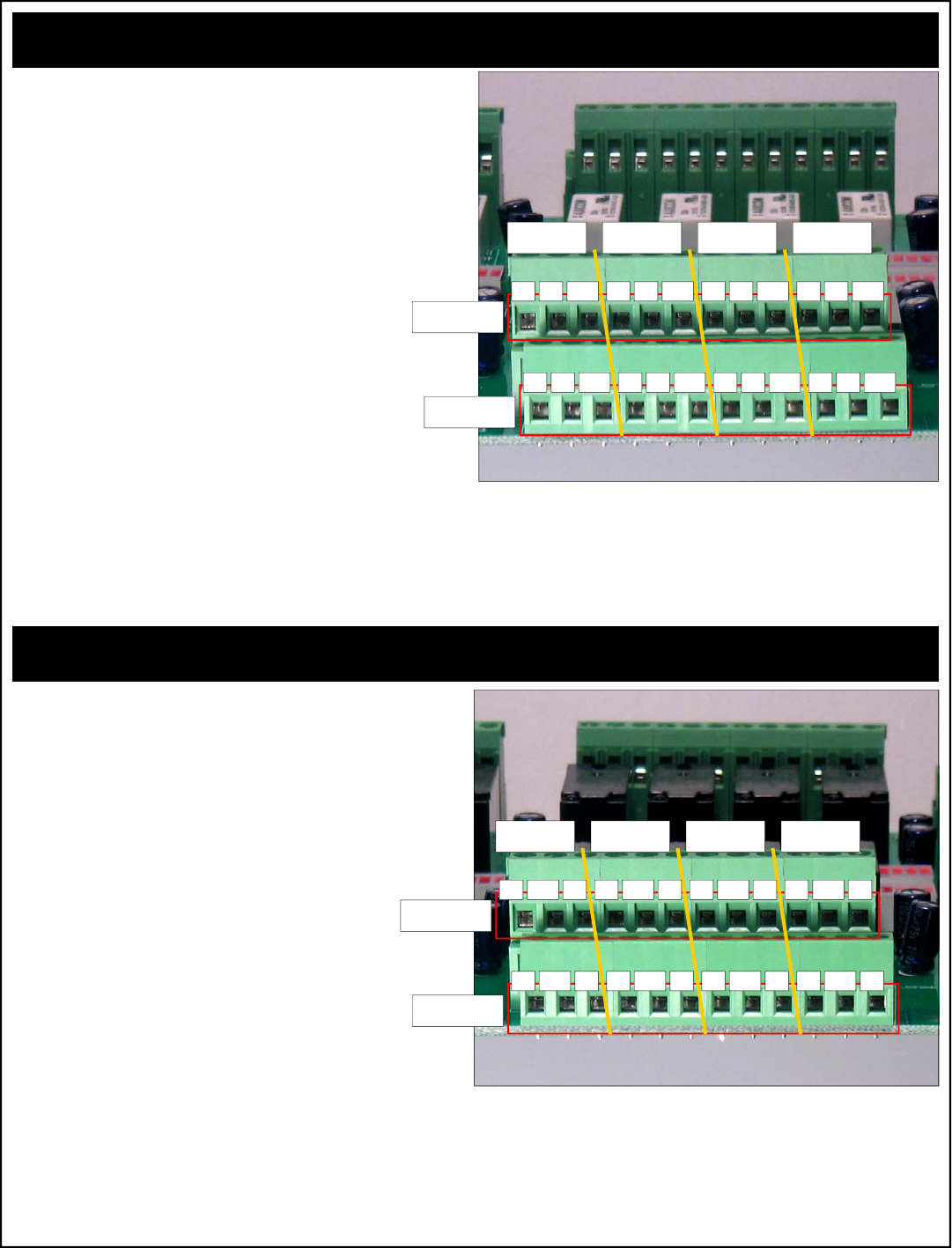
Connecting 1-Amp DPDT Relays (White Relays)
Connector Pinouts for 1-Amp DPDT Series Controllers
Any time you see one of our relay controllers with a green 24-Position
terminal block and small white relays labeled AXICOM on the board,
you can assume the wiring connections shown to the right will always
apply. Always view the connector from the angle shown in the picture
to the right. This will ensure connections are consistently made to 1A
DPDT series controllers.
A DPDT relay has two separate switches inside each relay. These
switches are labeled Switch A and Switch B in the diagram at right.
Switches A and B are completely separated from each other, there is
no electrical connection between these switches. When a DPDT relay
is activated, both switches A and B “activate” or more appropriately
change position at the same time. In the diagram at right,
each connection is labeled NO, NC and COM.
COM: Common
This terminal is connected to NC when relay is off.
This terminal swings over to NO when the relay is on.
NO: Normally Open
This terminal has no connection with the relay is off.
This terminal is connected to COM when the relay is on.
NC: Normally Close
This terminal is connected to COM when the relay is off.
This terminal has no connection with the relay is on.
Connector Pinouts for 3-Amp and 5-Amp DPDT Series Controllers
Any time you see one of our relay controllers with a green 24-Position
terminal block and black relays on the board, you can assume the wir-
ing connections shown to the right will always apply. Always view the
connector from the angle shown in the picture to the right. This will
ensure connections are consistently made to 3A and 5A DPDT series
controllers.
A DPDT relay has two separate switches inside each relay. These
switches are labeled Switch A and Switch B in the diagram at right.
Switches A and B are completely separated from each other, there is
no electrical connection between these switches. When a DPDT relay
is activated, both switches A and B “activate” or more appro-
priately change position at the same time. In the diagram at
right, each connection is labeled NO, NC and COM.
COM: Common
This terminal is connected to NC when relay is off.
This terminal swings over to NO when the relay is on.
NO: Normally Open
This terminal has no connection with the relay is off.
This terminal is connected to COM when the relay is on.
NC: Normally Close
This terminal is connected to COM when the relay is off.
This terminal has no connection with the relay is on.
Connecting 3-Amp/5-Amp DPDT Relays (Black Relays)
Switch A
Switch B
Relay Relay Relay Relay
NC COM NO
NC COM NO
NC COM NO
NC COM NO
NC COM NO
NC COM NO
NC COM NO
NC COM NO
Relay Relay Relay Relay
Switch A
Switch B
NC COM NO
NC COM NO
NC COM NO
NC COM NO
NC COM NO
NC COM NO
NC COM NO
NC COM NO
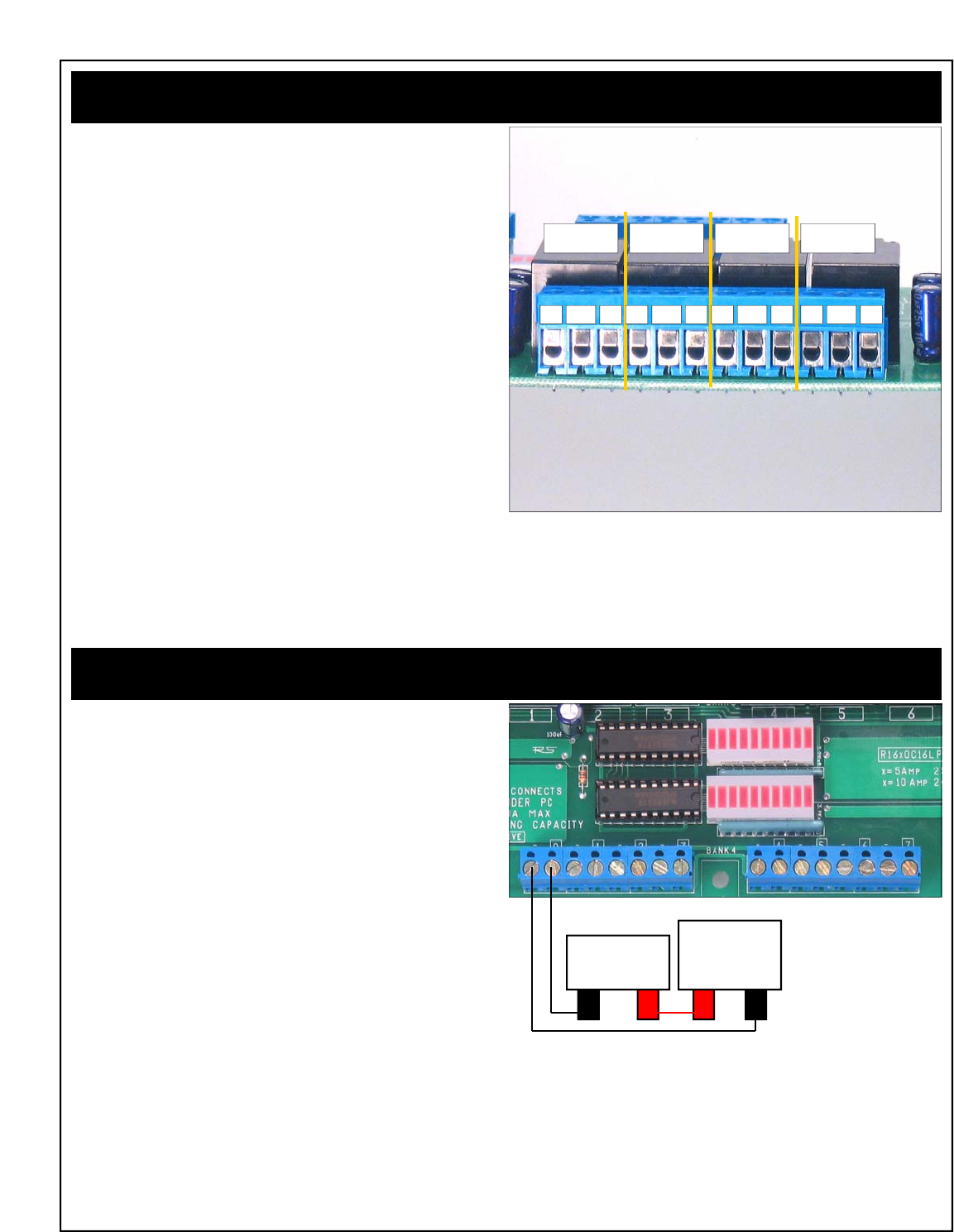
Connecting 5-Amp/10-Amp SPDT Relays
Connector Pinouts for 5-Amp / 10-Amp SPDT Series Controllers
Any time you see one of our relay controllers with blue 12-Position
terminal blocks, you can assume the wiring connections shown to the
right will always apply. Always view the connector from the angle
shown in the picture to the right. This will ensure connections are con-
sistently made to 5 and 10-Amp SPDT series controllers.
A SPDT relay has one switch inside each relay. When a SPDT relay is
activated, the switch changes position. In the diagram at right, each
connection is labeled NO, NC and COM. Please see the comments
below to better understand how connections are made.
COM: Common
This terminal is connected to NC when relay is off.
This terminal swings over to NO when the relay is on.
NO: Normally Open
This terminal has no connection with the relay is off.
This terminal is connected to COM when the relay is on.
NC: Normally Close
This terminal is connected to COM when the relay is off.
This terminal has no connection with the relay is on.
Connecting Open-Collector Outputs
WARNING: DO NOT CONNECT OC OUTPUTS WHILE POWER IS
APPLIED TO THE CONTROLLER. THIS WILL DAMAGE THE OUT-
PUT DRIVER CHIP.
Any time you see one of our ProXR Series relay controllers with blue
terminal blocks (8 or 16-Position), you can assume the wiring connec-
tions shown to the right will always apply. Always view the connector
from the angle shown in the picture to the right. This will ensure con-
nections are consistently made to the OC Outputs.
Open Collector outputs are ideal for adding external relays, small lights,
LEDs, and other small loads under 150ma at 12VDC. OC outputs work
by connecting an external device to ground. For instance, to connect
an external relay to an open collector output, you will connect one of
the two power leads directly to the OC output. The other relay power
lead should be connected to a power supply. The ground of the power
supply should be shared with the Ground leads on the OC output.
When the OC output is activated, the relay will activate by making a
connection between the relay and ground. A voltage should always be
present on the relay (except during connection).
Connecting O.C. Outputs to External Devices
Relay Relay Relay Relay
NC COM NO NC COM NO NC COM NO NC COM NO
- +
EXTERNAL
RELAY
+ -
EXTERNAL
POWER
SUPPLY
Repeat the circuit as shown above for every pair of outputs. On
some controllers, the two sets 8-position blue terminal blocks are
together, forming a single blue 16-position terminal block. Con-
nections are the same for these controllers. Don’t forget, this cir-
cuit will share the grounds of your external power supply with the
ground and RS232 ground of the controller. NEVER CONNECT
EXTERNAL DEVICES WHILE THE CONTROLLER IS POWERED UP.

Part Numbers:
R165OC16LP
R1610OC16LP
R325PROXR
R3210PROXR
Revision A boards have an error in the silk screen. A small dia-
gram is shown on the board indicating relay connections. While
the diagram is correct, the Labeling of NC and NO connections is
backwards. Revision B boards are in production that correct this
silk screen error.
Troubleshooting Considerations
If you experience any problems with a relay bank shutting down (all 8
relays turning off) when a relay is activated, please consult the section
of this manual on EMI (page 18). Chances are good that the problem is
caused because the load is too inductive for our controller, though page
18 may offer a solution. We are planning to develop an EMI edition of
some controllers that is designed to handle highly inductive loads.
As of 12/21/2005, there are no known Version 17 firmware bugs. If you
discover any problems with this device, please contact us.
Last Minute Notes

ProXR Series Command Set www.controlanything.com
Command Parameters Command Decription Returned Dat
a
254, 0 Relay 0 Of
f
85
254, 1 Relay 1 Of
f
85
254, 2 Relay 2 Of
f
85
254, 3 Relay 3 Of
f
85
254,4 Relay 4 Of
f
85
254, 5 Relay 5 Of
f
85
254, 6 Relay 6 Of
f
85
254, 7 Relay 7 Of
f
85
254, 8 Relay 0 On 85
254, 9 Relay 1 On 85
254, 10 Relay 2 On 85
254, 11 Relay 3 On 85
254, 12 Relay 4 On 85
254, 13 Relay 5 On 85
254, 14 Relay 6 On 85
254, 15 Relay 7 On 85
254, 16 Report Relay 0 Statu
s
0-1
254, 17 Report Relay 1 Statu
s
0-1
254, 18 Report Relay 2 Statu
s
0-1
254, 19 Report Relay 3 Statu
s
0-1
254, 20 Report Relay 4 Statu
s
0-1
254, 21 Report Relay 5 Statu
s
0-1
254, 22 Report Relay 6 Statu
s
0-1
254, 23 Report Relay 7 Statu
s
0-1
254, 24 Reports Status of Relay Ban
k
0-255**
254, 25 Turns On Automatic Relay Refreshin
g
85
254, 26 Turns Off Automatic Relay Refreshin
g
85
254, 27 Turns On Reporting Mode (Setting Stored
)
85
254, 28 Turns Off Reporting Mode (Setting Stored
)
85
254, 29 Turn Off All Relay
s
85
254, 30 Turn On All Relay
s
85
254, 31 Inverts All Relays in Ban
k
85
254, 32 Reversed Order of Relays in Ban
k
85
254, 33 Test 2-Way Communication 85
254, 34 Sends Currently Selected Relay Ban
k
0-32
254, 35 Store Relay Automatic Refresh Settin
g
85
254, 36 Reports the Automatic Refresh Setting 0-1
254, 37 Manually Refresh All Relay Bank
s
85
254, 40 Relay(0-255
)
Set Status of All Relays at One Tim
e
85
254, 41 No Function 85
254, 42 Bank(0-32) Store Startup Status of Relays in Selected Ban
k
85
254, 43 Bank(0-32) Recall Startup Status of Relays in Selected Ban
k
0-255**
254, 46 Relay(0-255
)
Turn On One Relay ONLY, Safe Break Before Mak
e
85
254, 47 Relay(0-255
)
Turn Off a Relay Specified by its Relay Numbe
r
85
254, 48 Relay(0-255
)
Turn On a Relay Specified by its Relay Numbe
r
85
254, 49 Bank(0-32) Sets the Current Relay Banks Commands are Directed T
o
85
254, 50 Timer(50-66) Choose a Duration Timer (16 Timers Available
)
Hour(0-255
)
Relay Will Stay Active for Selected Hour
s
Minute(0-255
)
Relay Will Stay Active for Selected Minute
s
Second(0-255
)
Relay Will Stay Active for Selected Second
s
Relay (0-255
)
Assign a Relay to This Time
r
85
254, 50 Timer(70-86) Choose a Pulse Timer (16 Timers Available)
Hour(0-255
)
Relay Will At the End of Selected Hours
Minute(0-255
)
Relay Will At the End of Selected Minute
s
Second(0-255
)
Relay Will At the End of Selected Seconds
Relay (0-255
)
Assign a Relay to This Time
r
85
254, 50 Timer(90-106) Choose a Duration Timer (Timer Activated Using Different Command
)
Hour(0-255
)
Relay Will Stay Active for Selected Hour
s
Minute(0-255
)
Relay Will Stay Active for Selected Minute
s
Second(0-255
)
Relay Will Stay Active for Selected Second
s
Relay (0-255
)
Assign a Relay to This Time
r
85
254, 50 Timer(110-126) Choose a Pulse Timer (Timer Activated Using Different Command
)
Hour(0-255
)
Relay Will At the End of Selected Hours
Minute(0-255
)
Relay Will At the End of Selected Minute
s
Second(0-255
)
Relay Will At the End of Selected Seconds
Relay (0-255
)
Assign a Relay to This Time
r
85
254, 50, 130 Timer(1-16) Query Selected Time
r
Device Returns Current Hour of Time
r
Hour(0-255
)
Device Returns Current Minute of Time
r
Minute(0-255
)
Device Returns Current Second of Time
r
Sedond(0-255
)
Device Returns Relay Number that is Assigned to Selected Time
r
Relay(0-255
)

254, 50, 131 TimeLSB(0-255) Manually Activate/Halt Selected Timers (Least Sig. Byte
)
TimeMSB(0-255) Manually Activate/Halt Selected Timers (Most Sig. Byte
)
85
254, 50, 132 CalibrateLSB(0-255
)
Sets the LSB Calibration of the Timer (Stores in Config. Mode Only
)
CalibrateMSB(0-255
)
Sets the MSB Calibration of the Timer (Stores in Config. Mode Only
)
85
254, 50, 133 Retrieves the Calibration Value of the Time
r
Least Significant Bytes will be Sent First (LSB
)
CalibrateLSB(0-255
)
Most Significant Bytes will be Sent Last (MSB
)
CalibrateMSB(0-255
)
254, 50, 134 Calibrators ON, Meaure Time Between Data to Help Set Calibratio
n
85
Patches In an ASCII Character Output Signifying the Start of a Time
r
Start(90)
Patches In an ASCII Character Output Signifying the End of a Time
r
Stop(91)
254, 50, 13
5
Calibrators OFF, Timers Will Not Signify Start/Stop 85
254, 50, 136 Retrieves the Repititions Value (Fights EMI by Holding Relays On
)
Reps(1-255
)
254, 50, 137 REPS(1-255) Stores the Repititions Value (Config. Mode Only
)
85
254, 50, 138 Retrieves the Character Delay Value (Delay Between Bytes Sent to PC
)
CDEL(3-255)
254, 50, 139 CDEL(3-255) Stores the Character Delay (Config. Mode Only
)
85
254, 50, 140 Retrieves the Number of Relay Banks Attached to Controlle
r
ATBanks(1-255)
254, 50, 141 ATBanks(1-255) Stores the Number of Relay Banks Attached (Config. Mode Only
)
85
254, 50, 144 Return to Safe Factory Default Values (Config. Mode Only
)
85
254, 50, 14
5
Get TestCycle Value (How Many Banks Tested in Config. Mode, 0=None
)
TCycle(0-32
)
254, 50, 146 TCycle(0-32
)
Set TestCycle Value (works in any mode
)
85
254, 50, 147 Attempt to Recover from a Controller that has Lost Communicatio
n
88
254, 100 Bank(0-32) Relay 0 Off in Specified Ban
k
85
254, 101 Bank(0-32) Relay 1 Off in Specified Ban
k
85
254, 102 Bank(0-32) Relay 2 Off in Specified Ban
k
85
254, 103 Bank(0-32) Relay 3 Off in Specified Ban
k
85
254, 104 Bank(0-32) Relay 4 Off in Specified Ban
k
85
254, 105 Bank(0-32) Relay 5 Off in Specified Ban
k
85
254, 106 Bank(0-32) Relay 6 Off in Specified Ban
k
85
254, 107 Bank(0-32) Relay 7 Off in Specified Ban
k
85
254, 108 Bank(0-32) Relay 0 On in Specified Ban
k
85
254, 109 Bank(0-32) Relay 1 On in Specified Ban
k
85
254, 110 Bank(0-32) Relay 2 On in Specified Ban
k
85
254, 111 Bank(0-32) Relay 3 On in Specified Ban
k
85
254, 112 Bank(0-32) Relay 4 On in Specified Ban
k
85
254, 113 Bank(0-32) Relay 5 On in Specified Ban
k
85
254, 114 Bank(0-32) Relay 6 On in Specified Ban
k
85
254, 115 Bank(0-32) Relay 7 On in Specified Ban
k
85
254, 116 Bank(0-32) Report Relay 0 Statu
s
0-1
254, 117 Bank(0-32) Report Relay 1 Statu
s
0-1
254, 118 Bank(0-32) Report Relay 2 Statu
s
0-1
254, 119 Bank(0-32) Report Relay 3 Statu
s
0-1
254, 120 Bank(0-32) Report Relay 4 Statu
s
0-1
254, 121 Bank(0-32) Report Relay 5 Statu
s
0-1
254, 122 Bank(0-32) Report Relay 6 Statu
s
0-1
254, 123 Bank(0-32) Report Relay 7 Statu
s
0-1
254, 124 Bank(0-32) Reports Status of Relay Ban
k
0-255**
254, 129 Bank(0-32) Turn Off All Relay
s
85
254, 130 Bank(0-32) Turn On All Relay
s
85
254, 131 Bank(0-32) Inverts All Relays in Ban
k
85
254, 132 Bank(0-32) Reversed Order of Relays in Ban
k
85
254, 140 Relay(0-255
)
Bank(0-32) Set Status of All Relays at One Tim
e
85
254, 142 Bank(0-32) Store Startup Status of Relays in Selected Ban
k
85
254, 143 Bank(0-32) Recall Startup Status of Relays in Selected Ban
k
0-255**
254, 246 Get Device Description Data from Controller: Ouputs Belo
w
Device ID Part 1 1
Device ID Part 2 0
Device Year of Design 205***
Device Firmware Version 17***
E3C Device Numbe
r
Default is 0
254, 247 Retrieve Stored E3C Device Numbe
r
E3CDevice(0-255)
254, 248 Enable All Devices Command <no output>
254, 249 Disable All Devices Command <no output>
254, 250 Device(0-255
)
Enable Selected Device <no output>
254, 251 Device(0-255
)
Disable Selected Device <no output>
254, 252 Device(0-255
)
Enable Selected Device ONLY, All Other Devices Disable
d
<no output>
254, 253 Device(0-255
)
Disable Selected Device ONLY, All Other Devices Enable
d
<no output>
254, 255 Device(0-255
)
Store E3C Device Number (Config Mode Only
)
<no output>
*Bank Value of 0 Directs Command to ALL Relay Banks
** Returns 32 Bytes of Data if Relay Bank is Set to 0
*** Subject to Change as Device is Improved
85 Values are Sent if Reporting Mode is ON
Copyright © 2006, National Control Devices www.controlanything.com

ProXR Enhanced Feature Controllers Introduction
RS-232, USB, Zigbee
In February, 2007, National Control Devices has released several
new, and enhanced controllers that support the ProXR command
set as shown in this manual. These new devices share the same
command set, but also offer additional commands for increased
functionality. The February, 2007 product release includes new
RS-232 controllers with built-in A/D conversion, as well as 6 new
USB versions, as well as 6 new Zigbee versions. In addition, the
ProXR software, as downloaded from our web site, has also been
enhanced to repair some minor bugs, and add support for new
controllers that have an enhanced feature set. There are many
changes introduced by these new controllers, which will be dis-
cussed in greater detail as it applies. NCD devices that no-longer
have an RS-232 interface have been rightfully stripped of the E3C
command set (used for networking serial devices).
This section of the manual covers the new features added to the
updated line of controllers. This portion of the manual ONLY cov-
ers the part numbers indicated below:
RS-232 Devices
Xxxxxxxxx
Xxxxxxxxx
xxxxxxxxx
USB Devices
UADR220PROXR USB, 2-Relays, 20-Amp, 8-Channels 8/10-bit A/D
UADR230PROXR USB, 2-Relays, 30-Amp, 8-Channels 8/10-bit A/D
UADR45PROXR USB, 4-Relays, 5-Amp, 8-Channels 8/10-bit A/D
UADR410PROXR USB, 4-Relays, 10-Amp, 8-Channels 8/10-bit A/D
UADR85PROXR USB, 8-Relays, 5-Amp, 8-Channels 8/10-bit A/D
UADR810PROXR USB, 8-Relays, 10-Amp, 8-Channels 8/10-bit A/D
Zigbee Devices
Xxxxxxxxxxxx
Xxxxxxxxxxxx
Xxxxxxxxxxxx
Xxxxxxxxxxxx
RS-232 Enhancement Overview
1) Baud Rate is Now Set using our ProXR software instead of using
DIP switches.
2) The Program/Run Jumper can Now be Changed while power is
applied to the controller, however, some parameters will not take
effect until the device is power cycled.
3) 8-Channels of Analog to Digital Conversion has been added to the
controller, supporting 8-Bit or 10-Bit resolution. In addition, new
commands allow you to read a single channel at a time or multiple
channels at one time.
4) A/D converters employ a resistor network that allows you to pull all
channels up or down. This effectively keeps the input channels
quiet without any external resistors. The pull-up/pull-down feature
is jumper selectable. Removing the jumper floats the inputs with
20Kresistance between neighboring channels.
5) Integrated jumper-selectable temperature sensor is now integrated
into the controller. This sensor is tied to Analog Input channel 8.
User may choose to use input channel 8 or tie input channel 8 to
the temperature sensor under jumper selection. The controller
supports the Microchip 9701A temperature sensor. Complete data
sheets for the 9701A are available from www.microchip.com.
6) Unused relay output channels are available for control of external
relays.
USB Enhancement Overview
1) Integrated FTDI USB to Serial Converter. Device mounts as a
virtual COM port, user speaks to device using the assigned COM
port. User may choose COM port assignment by changing the
driver settings in the Device Manager. Virtual COM port Drivers
are available for most operating systems currently in use, including
Windows, MAC, UNIX, and Sun.
2) Three USB LEDs indicate USB Connection and Data Activity.
3) Baud Rate is fixed at 115.2K Baud, 8 Data bits, 1 Stop bit, No
Parity.
4) USB Relay controllers are NOT USB Bus powered. A relay con-
troller goes against USB Bus power specifications because of its
ability to surge power on the USB Bus; therefore, most NCD relay
controllers will not likely support USB Bus power features. An
external +12VDC supply will be required.
5) The Program/Run Jumper can Now be Changed while power is
applied to the controller, however, some parameters will not take
effect until the device is power cycled.
6) 8-Channels of Analog to Digital Conversion has been added to the
controller, supporting 8-Bit or 10-Bit resolution. In addition, new
commands allow you to read a single channel at a time or multiple
channels at one time.
7) A/D converters employ a resistor network that allows you to pull all
channels up or down. This effectively keeps the input channels
quiet without any external resistors. The pull-up/pull-down feature
is jumper selectable. Removing the jumper floats the inputs with
20Kresistance between neighboring channels.
8) Integrated jumper-selectable temperature sensor is now integrated
into the controller. This sensor is tied to Analog Input channel 8.
User may choose to use input channel 8 or tie input channel 8 to
the temperature sensor under jumper selection. The controller
supports the Microchip 9701A temperature sensor. Complete data
sheets for the 9701A are available from www.microchip.com.
9) Unused relay output channels are available for control of external
relays.
Zigbee Enhancement Overview
1) Complete support for Zigbee protocol using Maxstream Zigbee
interface modules. Zigbee is essentially a wireless 2-way serial
port protocol, allowing you to speak to a device wirelessly as
though it were physically attached to the serial port of your com-
puter.
2) Baud Rate to Zigbee modem is user-programmable. A Zigbee
modem if required to communicate to our relay controller. Zigbee
modems connect to the USB port of your computer and are USB
Bus powered.
3) The Program/Run Jumper can Now be Changed while power is
applied to the controller, however, some parameters will not take
effect until the device is power cycled.
4) 8-Channels of Analog to Digital Conversion has been added to the
controller, supporting 8-Bit or 10-Bit resolution. In addition, new
commands allow you to read a single channel at a time or multiple
channels at one time.
5) A/D converters employ a resistor network that allows you to pull all
channels up or down. This effectively keeps the input channels
quiet without any external resistors. The pull-up/pull-down feature
is jumper selectable. Removing the jumper floats the inputs with
20Kresistance between neighboring channels.
6) Integrated jumper-selectable temperature sensor is now integrated
into the controller. This sensor is tied to Analog Input channel 8.
User may choose to use input channel 8 or tie input channel 8 to
the temperature sensor under jumper selection. The controller
supports the Microchip 9701A temperature sensor. Complete data
sheets for the 9701A are available from www.microchip.com.
7) Unused relay output channels are available for control of external
relays.
Elements of this diagram may be useful for other devices we offer. We have not included photos of every controller we offer in this manual;
instead, we have detailed the significant variations. Our controllers contain many common elements in different combinations.

USB and Zigbee Device Communications
Talking to USB and Zigbee devices is just like talking to a RS-232 de-
vice. When a USB device is plugged into the USB port of your com-
puter, the USB device will be assigned a COM port. Your software
simply speaks to the USB device as though it were a real COM port.
This offers optimum flexibility in terms of software and hardware com-
patibility. Zigbee devices work exactly the same way, they mount as a
COM port and you speak to the device as though it were a real serial
device attached to your computer. USB devices emulate a COM port.
Zigbee devices emulate a wireless serial port. Communication to USB
devices is fixed at 115.2K baud. Communicating to a wireless Zigbee
device requires a Zigbee modem. You can configure the Zigbee mo-
dem baud rate and other parameters using X-CTU, available for free
download by clicking here.
If the Zigbee modem or USB device does not mount as the desired
COM port, you may change the COM assignment using the Device
Manager as part of the System Control Panel on your Windows system.
USB and Zigbee devices differ from RS-232 devices in that they do not
have a E3C command set, used for networking RS-232 devices. In
addition, USB devices only speak at 115.2K baud.
Your computer can speak to a Zigbee modem at any baud rate. Zigbee
modems communicate with each other at 115.2K baud. Remote Zig-
bee devices communicate with the on-board Zigbee transceiver at
115.2K baud. For best performance, your computer should speak to
the Zigbee modem at 115.2K baud.
Networking Zigbee Devices:
It is possible to speak to many Zigbee devices within a local area.
Each Zigbee device is hard coded with a device ID number. The de-
vice ID number is printed on the bottom side of the Zigbee module.
This Zigbee module can be easily removed. You can also query all
Zigbee modules to determine all device ID numbers within range. The
Zigbee protocol is extensive, and will not be covered in any NCD docu-
mentation. Instead, we will focus our documentation on sending com-
mands to remote devices that support the Zigbee protocol. In other
words, we will show you how to talk to our devices for controlling relays
and reading data. If you wish to learn about the extensive features of
the Zigbee protocol (also known as 802.15.4), this documentation can
be downloaded from the MaxStream web site by clicking here. We
highly suggest reading this documentation as it has more information
on speaking to several different Zigbee devices and hopping com-
mands across wireless networks.
To this point, we have focused heavily on USB / Zigbee communica-
tions as it focuses on RS-232 emulation. From this point forward, it
should be very easy to speak to devices. Both USB and Zigbee mod-
ules offer 100% emulation of a COM port and offer a completely trans-
parent communication layer. We have chosen these communication
methods because we believe they offer the best compatibility and
quickest implementation time.
Elements of this diagram may be useful for other devices we offer. We have not included photos of every controller we offer in this manual;
instead, we have detailed the significant variations. Our controllers contain many common elements in different combinations.
STOP: Before Connecting USB Devices or Zigbee modems to your
computer, you should start by installing the latest FTDI USB driv-
ers on your computer. Installing the drivers before connecting the
hardware will make setup easier. Click Here for Latest Drivers
Developing Software for Serial Communications
Despite the connectivity you have chosen (RS-232, USB, or Zigbee),
the easiest way to speak to NCD devices is to make use of serial com-
munications. Serial communications is supported by nearly all pro-
gramming languages, and it is very easy to send simple commands to
NCD devices using any language you may require.
We suggest the following resources to help get you started:
Page 8 of this manual explains how data should be formatted as it per-
tains to speaking to NCD devices.
Visual Basic 4, 5, 6
We have also posted a Visual Basic 6 tutorial in the “Developers Tool-
box” section of our web site. This tutorial is available by clicking here.
This same tutorial can be also be downloaded along with a .NET tuto-
rial in the Universal Device Manual available from our web site by click-
ing here.
.NET Express
You can also use Visual Basic Express to speak to NCD devices. VB
Express is free from Microsoft. At the time of writing, Microsoft offers a
free download by clicking here. Click the large camouflaged “Download
Now” button on the right side of the screen.
We have also posted a tutorial for using .NET Express in the Universal
Device Manual, available from our web site by clicking here.
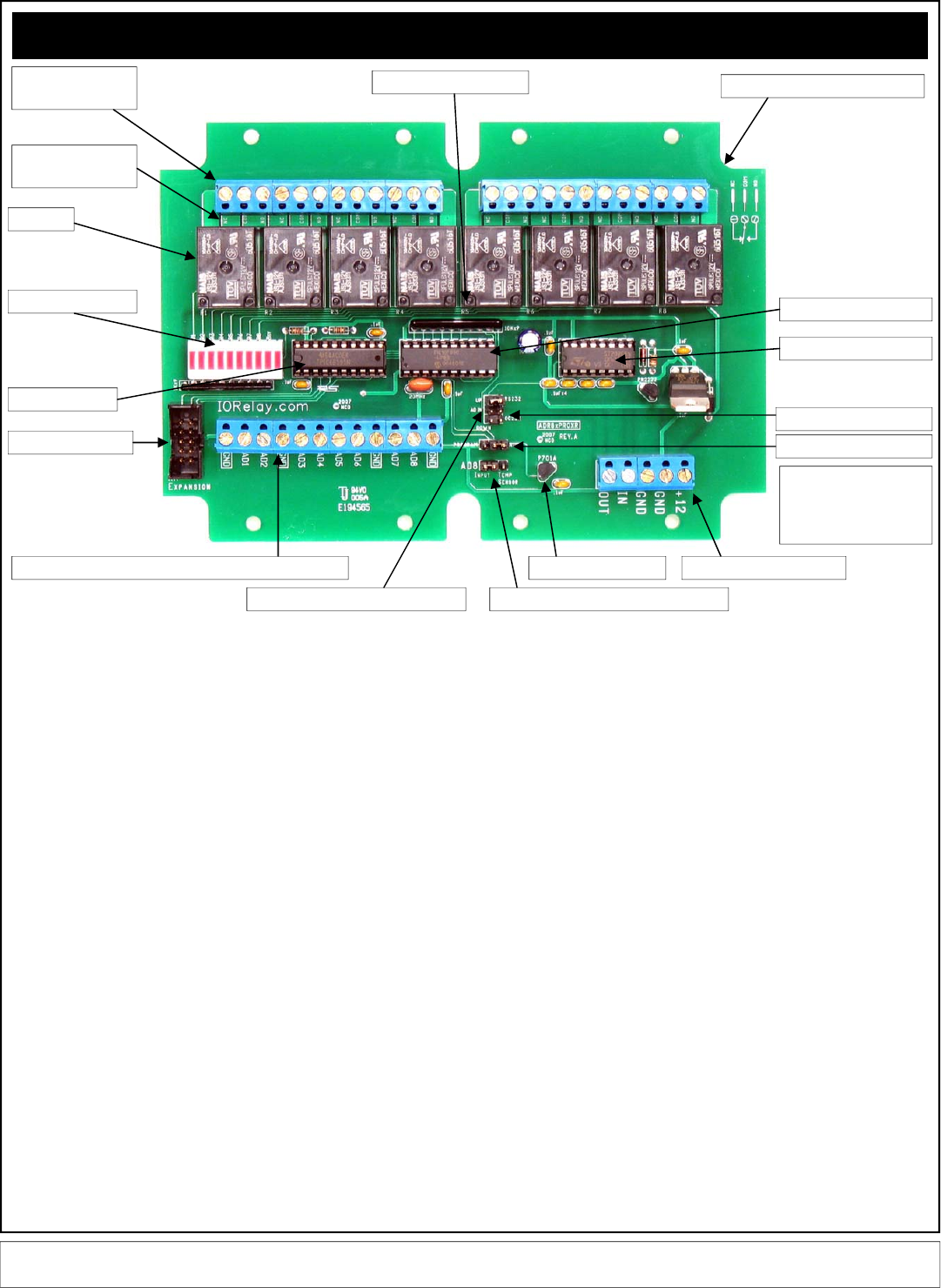
ProXR Enhanced RS-232
RS-232 Enhancements
In February, 2007, NCD released a number of ProXR enhanced controllers. These
new ProXR controllers are available with an optional enclosure, which accounts for the
unusual shape of the circuit board. There are many versions of the ProXR series that
have enhanced features. The above map explains the updated layout.
A: There are 3 terminals per relay: NC (Normally Closed), COM (Common), and NO
(Normally Open). Then the relay is OFF, Common is connected to Normally Closed.
When the relay is ON, Common is connected to the Normally Open. Relay activation
time is approximately 5ms. Relay deactivation takes approximately 10ms.
B: The circuit board on the model shown is labeled with NC, COM, and NO. Some
models of relay have contacts directly on the top side of the relay. In this case, the
PCB will not be labeled with NC, COM, or NO. Instead, look carefully near the contacts
of the relay, the relay connections are labeled directly on the relay near the contacts.
C: The relays shown above are 5-Amp SPDT. We offer relay in 1-Amp, 3-Amp, 5-Amp,
10-Amp, 20-Amp, 30-Amp, SPST, SPDT, and DPDT varieties.
D: LED status lights. When powered, the first LED is lit (far right in the photo, bottom
LED on other models). One LED is assigned to each relay in the same order as the
relays are shown above. The second LED from the left will light when a command is in
process.
E: Latch driver chip activates the relays by connecting them to ground under computer
control.
F: XR Expansion port allows this controller to speak to a total 256 relays using expan-
sion relay boards.
G: Analog Inputs allow this controller to read 8 different voltage levels or contact clo-
sures. Input voltage is between 0 and +5VDC. Do not exceed this voltage rating or
damage to the CPU will result.
H: Pull Up / Pull Down Resistors keep the analog inputs from floating. When the
jumper is installed in the UP position, each of the analog inputs is connected to +5VDC
through a 10K resistor. When the jumper is installed in the DOWN position, each of the
analog inputs is connected to Ground through a 10K resistor. When this jumper is
removed, the analog inputs “Float” (not recommended for most applications).
Neighboring inputs are connected to each other with a total of 20K resistance between
immediate neighboring inputs.
I: Analog Input #8 can be connected to an external source when this jumper is set to
the Input position. When set to Temp Sensor position, this input is no-longer available
to the user. Instead, input channel #8 is connected to a internal MCP9701A temperate
sensor.
J: MCP9701A temperature sensor. This sensor delivers a analog voltage in proportion
to temperature. This voltage can be read by input channel #8 when the AD8 jumper is
set to the Temp Sensor position. Current software does not convert the analog value to
a actual temperature. Please consult the MCP9701A data sheet from
www.microchip.com for complete details on converting the voltage to a temperature.
K: Power Data Connector. This is the RS-232 interface and Power connections for the
controller. +12VDC at 100ma is required for “standby” with no relays activated. Allow
up to 100ma for each relay that is activated. The Power Supply Ground on the control-
ler is shared with the RS-232 Ground. The IN refers to the RS-232 input, this connec-
tion ties to the RS-232 output of your computer. The OUT refers to the RS-232 output.
This connection ties to the RS-232 input on your computer. See page 5 of this manual
for complete details on RS-232 connection of this controller.
L: The Program/Run jumper determines if the controller is in Program mode (which
allows you to make configuration changes via ProXR software, such as baud rate and
timing parameters), or Run mode, which write-protects the on-board memory and
should be used for normal daily operation. Program mode operates at a fixed baud
rate of 38.4K baud. The baud rate for Runtime mode is user programmed while in
Program mode. Runtime mode supports several different baud rates, please run the
ProXR software to configure the Runtime baud rate.
M: RS-232 / OC-232 Data Output formal select jumper. When connecting one device
to a computer, use the RS-232 mode. When connecting several devices to a computer
using the RSB serial booster, set the jumper to OC-232 mode. See page 7 for details.
N: This chip converts CPU data to RS-232 voltage levels.
O: NCD Customized PIC16F690 CPU running at 20 MHz.
P: PCB Outline Compatible with SERPAC SR171 series enclosures.
Q: Relay number identification labels, R1 through R8. One assigned to each relay.
D: LED Status Lights
F: XR Expansion Port
G: Analog Input Channels: Do Not Exceed +5VDC on Inputs
E: Relay Driver
C:Relays
A: Relay Connections:
3 Per Relay
B: Relay Connection
Labels: NC COM NO
J: Temperature Sensor K: Power/Data Connector
I: AD8 / Temperature Senor Select Jumper
M: RS-232 / OC232 Jumper
L: Program / Run Jumper
H: 10K Pull-Up / Pull-Down Jumper
O: ProXR Enhanced CPU
N: RS-232 Transceiver
P: SERPAC Enclosure Form factor
Q: Relay Number Labels
Elements of this diagram may be useful for other devices we offer. We have not included photos of every controller we offer in this manual;
instead, we have detailed the significant variations. Our controllers contain many common elements in different combinations.
When using the quick start
kit, keep in mind, it will NOT
fit inside the enclosure, but
it will help you get started.
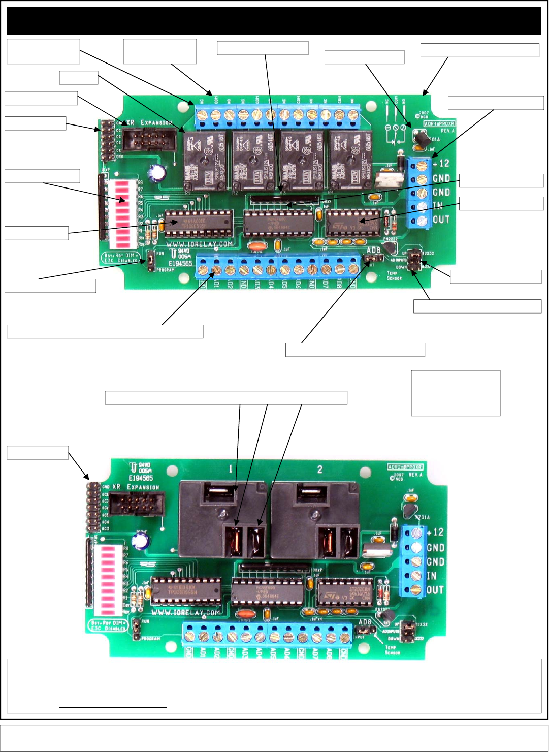
ProXR Enhanced RS-232
D: LED Status Lights
F: XR Expansion Port
G: Analog Input Channels: Do Not Exceed +5VDC on Inputs
E: Relay Driver
C:Relays
A: Relay Connections:
3 Per Relay
B: Relay Connection
Labels: NC COM NO J: Temperature Sensor
K: Power/Data Connector
I: AD8 / Temperature Senor Select Jumper
M: RS-232 / OC232 Jumper
L: Program / Run Jumper
H: 10K Pull-Up / Pull-Down Jumper
O: ProXR Enhanced CPU
N: RS-232 Transceiver
P: SERPAC Enclosure Form factor
Q: Relay Number Labels
R: OC Outputs
Small Embossed Marks in the indicated Locations Mark NC, COM, and NO
R: This controller has spare OC outputs. These outputs can be used to drive external relays up to 24VDC at 150ma per relay. To use the output, you will need to connect a exter-
nal power supply to your relays, providing a positive voltage into the coil of the external relay. The GND connection on this board should be connected to the GROUND of your
external power supply. Each of the spare OC outputs should be connected to the other remaining terminal on the external relay coil. This controller activates external relays by
connecting the relay coil to ground under computer control. ALL POWER SUPPLIES MUST BE POWERED DOWN WHILE MAKING CONNECTIONS. FAILURE TO FOLLOW
THIS CAUTION WILL DAMAGE THE DRIVER CHIP.
R: OC Outputs
Elements of this diagram may be useful for other devices we offer. We have not included photos of every controller we offer in this manual;
instead, we have detailed the significant variations. Our controllers contain many common elements in different combinations.
When using the quick start
kit, keep in mind, it will NOT
fit inside the enclosure, but
it will help you get started.
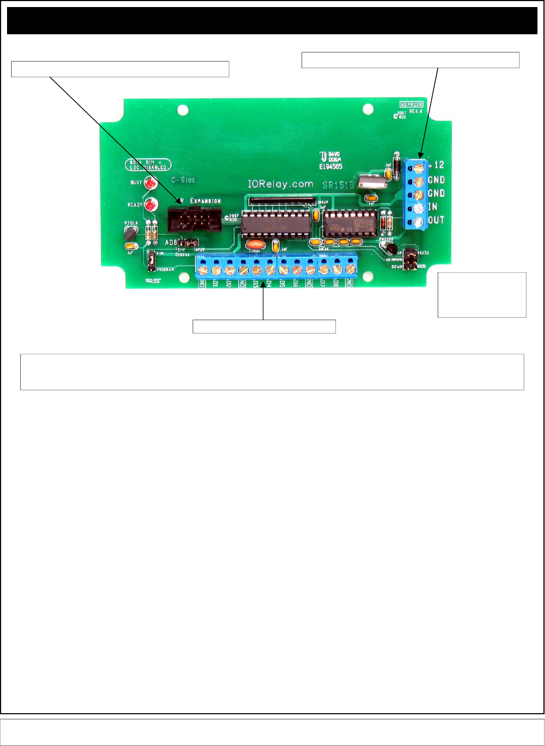
ProXR Enhanced RS-232
The ADPROXR shown above has all the features of the controllers shown on the previous pages, but has no on-board relays. You may add relays at any time to this
controller using the XR expansion port. The firmware on this controller is identical to the firmware shown on the previous two pages. This controller only requires about
100ma and is compatible with the SERPAC SR151 series enclosures.
8-Channels of 8-bit / 10-bit Analog Inputs
XR Expansion Port allows you to add relays as your needs grow.
Power / Data Connections are Detailed on Page 5 of this manul.
Elements of this diagram may be useful for other devices we offer. We have not included photos of every controller we offer in this manual;
instead, we have detailed the significant variations. Our controllers contain many common elements in different combinations.
When using the quick start
kit, keep in mind, it will NOT
fit inside the enclosure, but
it will help you get started.
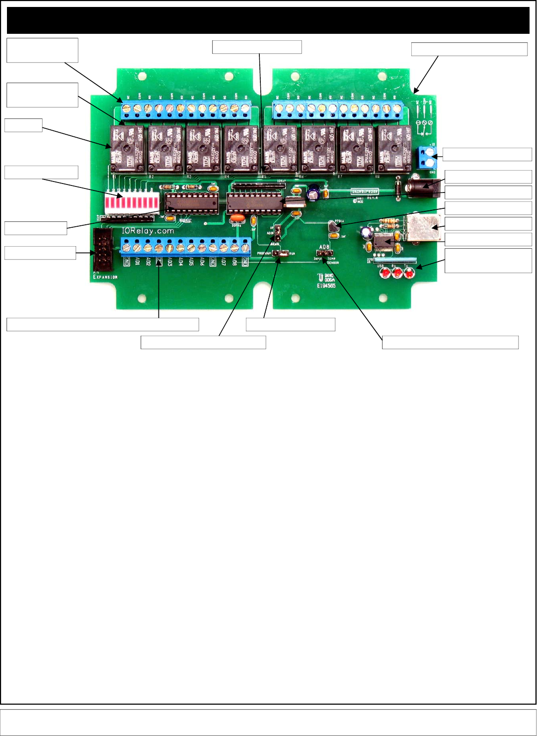
ProXR Enhanced USB
USB Enhancements
In February, 2007, NCD released a number of ProXR enhanced controllers. These
new ProXR controllers are available with an optional enclosure, which accounts for the
unusual shape of the circuit board. There are many versions of the ProXR series that
have enhanced features. The above map explains the updated layout.
A: There are 3 terminals per relay: NC (Normally Closed), COM (Common), and NO
(Normally Open). Then the relay is OFF, Common is connected to Normally Closed.
When the relay is ON, Common is connected to the Normally Open. Relay activation
time is approximately 5ms. Relay deactivation takes approximately 10ms.
B: The circuit board on the model shown is labeled with NC, COM, and NO. Some
models of relay have contacts directly on the top side of the relay. In this case, the
PCB will not be labeled with NC, COM, or NO. Instead, look carefully near the contacts
of the relay, the relay connections are labeled directly on the relay near the contacts.
C: The relays shown above are 5-Amp SPDT. We offer relay in 1-Amp, 3-Amp, 5-Amp,
10-Amp, 20-Amp, 30-Amp, SPST, SPDT, and DPDT varieties.
D: LED status lights. When powered, the first LED is lit (far right in the photo, bottom
LED on other models). One LED is assigned to each relay in the same order as the
relays are shown above. The second LED from the left will light when a command is in
process.
E: Latch driver chip activates the relays by connecting them to ground under computer
control.
F: XR Expansion port allows this controller to speak to a total 256 relays using expan-
sion relay boards.
G: Analog Inputs allow this controller to read 8 different voltage levels or contact clo-
sures. Input voltage is between 0 and +5VDC. Do not exceed this voltage rating or
damage to the CPU will result.
H: Pull Up / Pull Down Resistors keep the analog inputs from floating. When the
jumper is installed in the UP position, each of the analog inputs is connected to +5VDC
through a 10K resistor. When the jumper is installed in the DOWN position, each of the
analog inputs is connected to Ground through a 10K resistor. When this jumper is
removed, the analog inputs “Float” (not recommended for most applications).
Neighboring inputs are connected to each other with a total of 20K resistance between
immediate neighboring inputs.
I: Analog Input #8 can be connected to an external source when this jumper is set to
the Input position. When set to Temp Sensor position, this input is no-longer available
to the user. Instead, input channel #8 is connected to a internal MCP9701A temperate
sensor.
J: MCP9701A temperature sensor. This sensor delivers a analog voltage in proportion
to temperature. This voltage can be read by input channel #8 when the AD8 jumper is
set to the Temp Sensor position. Current software does not convert the analog value to
a actual temperature. Please consult the MCP9701A data sheet from
www.microchip.com for complete details on converting the voltage to a temperature.
K: USB Activity LEDs indicate connection to the USB port and data communications.
The LED labeled USB is lit once data has been established with the computer. The Rx
LED lights when data is received. The Tx LED lights when data is transmitted.
L: The Program/Run jumper determines if the controller is in Program mode (which
allows you to make configuration changes via ProXR software, such as baud rate and
timing parameters), or Run mode, which write-protects the on-board memory and
should be used for normal daily operation. The baud rate for the USB version of this
controller is fixed at 115.2K Baud in Configuration or Runtime mode. Baud rate cannot
be changed.
M: USB Type B Connector.
N: This chip converts emulates a RS-232 port at 115.1K Baud and mounts the device
as a COM port on your computer.
O: NCD Customized PIC16F690 CPU running at 20 MHz.
P: PCB Outline Compatible with SERPAC SR171 series enclosures.
Q: Relay number identification labels, R1 through R8. One assigned to each relay.
R: +12VDC 1 Amp power supply connection.
S: +12VDC 1 Amp 2.1mm Center Positive power supply connection.
You may choose to use any of the above power supply connections. We have pro-
vided two options so you may choose the one that best suits your requirements.
D: LED Status Lights
F: XR Expansion Port
G: Analog Input Channels: Do Not Exceed +5VDC on Inputs
E: Relay Driver
C:Relays
A: Relay Connections:
3 Per Relay
B: Relay Connection
Labels: NC COM NO
J: Temperature Sensor
R: Power Connector
I: AD8 / Temperature Senor Select Jumper
L: Program / Run Jumper
H: 10K Pull-Up / Pull-Down Jumper
O: ProXR Enhanced CPU
N: USB Transceiver
P: SERPAC Enclosure Form factor
Q: Relay Number Labels
M: USB Type B Connector
K: USB Connection and
Activity LEDs
S: 2.1mm Power Connector
Elements of this diagram may be useful for other devices we offer. We have not included photos of every controller we offer in this manual;
instead, we have detailed the significant variations. Our controllers contain many common elements in different combinations.
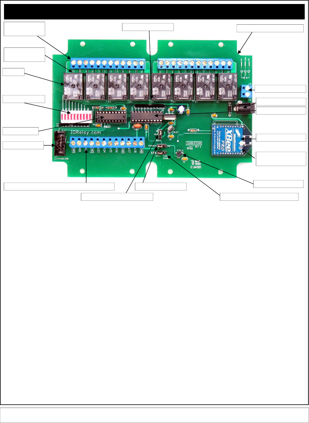
ProXR Enhanced Zigbee
Zigbee Enhancements
In February, 2007, NCD released a number of ProXR enhanced controllers. These
new ProXR controllers are available with an optional enclosure, which accounts for the
unusual shape of the circuit board. There are many versions of the ProXR series that
have enhanced features. The above map explains the updated layout.
A: There are 3 terminals per relay: NC (Normally Closed), COM (Common), and NO
(Normally Open). Then the relay is OFF, Common is connected to Normally Closed.
When the relay is ON, Common is connected to the Normally Open. Relay activation
time is approximately 5ms. Relay deactivation takes approximately 10ms.
B: The circuit board on the model shown is labeled with NC, COM, and NO. Some
models of relay have contacts directly on the top side of the relay. In this case, the
PCB will not be labeled with NC, COM, or NO. Instead, look carefully near the contacts
of the relay, the relay connections are labeled directly on the relay near the contacts.
C: The relays shown above are 5-Amp SPDT. We offer relay in 1-Amp, 3-Amp, 5-Amp,
10-Amp, 20-Amp, 30-Amp, SPST, SPDT, and DPDT varieties.
D: LED status lights. When powered, the first LED is lit (far right in the photo, bottom
LED on other models). One LED is assigned to each relay in the same order as the
relays are shown above. The second LED from the left will light when a command is in
process.
E: Latch driver chip activates the relays by connecting them to ground under computer
control.
F: XR Expansion port allows this controller to speak to a total 256 relays using expan-
sion relay boards.
G: Analog Inputs allow this controller to read 8 different voltage levels or contact clo-
sures. Input voltage is between 0 and +5VDC. Do not exceed this voltage rating or
damage to the CPU will result.
H: Pull Up / Pull Down Resistors keep the analog inputs from floating. When the
jumper is installed in the UP position, each of the analog inputs is connected to +5VDC
through a 10K resistor. When the jumper is installed in the DOWN position, each of the
analog inputs is connected to Ground through a 10K resistor. When this jumper is
removed, the analog inputs “Float” (not recommended for most applications).
Neighboring inputs are connected to each other with a total of 20K resistance between
immediate neighboring inputs.
I: Analog Input #8 can be connected to an external source when this jumper is set to
the Input position. When set to Temp Sensor position, this input is no-longer available
to the user. Instead, input channel #8 is connected to a internal MCP9701A temperate
sensor.
J: MCP9701A temperature sensor. This sensor delivers a analog voltage in proportion
to temperature. This voltage can be read by input channel #8 when the AD8 jumper is
set to the Temp Sensor position. Current software does not convert the analog value to
a actual temperature. Please consult the MCP9701A data sheet from
www.microchip.com for complete details on converting the voltage to a temperature.
K: Antenna Connector is compatible with type U.FL antennas and pigtail adapters.
L: The Program/Run jumper determines if the controller is in Program mode (which
allows you to make configuration changes via ProXR software, such as baud rate and
timing parameters), or Run mode, which write-protects the on-board memory and
should be used for normal daily operation. The baud rate for the USB version of this
controller is fixed at 115.2K Baud in Configuration or Runtime mode. Baud rate cannot
be changed.
N: Maxstream XBee/XBee Pro Zigbee Interface Module facilitates Wireless 2-Way
communications using the Zigbee protocol. 100% Zigbee compliant. This module may
be removed, the ID# is printed on the bottom of the module, useful when you want to
speak to a specific controller in a wireless network.
O: NCD Customized PIC16F690 CPU running at 20 MHz.
P: PCB Outline Compatible with SERPAC SR171 series enclosures.
Q: Relay number identification labels, R1 through R8. One assigned to each relay.
R: +12VDC 1 Amp power supply connection.
S: +12VDC 1 Amp 2.1mm Center Positive power supply connection.
You may choose to use any of the above power supply connections. We have pro-
vided two options so you may choose the one that best suits your requirements.
D: LED Status Lights
F: XR Expansion Port
G: Analog Input Channels: Do Not Exceed +5VDC on Inputs
E: Relay Driver
C:Relays
A: Relay Connections:
3 Per Relay
B: Relay Connection
Labels: NC COM NO
J: Temperature Sensor
R: Power Connector
I: AD8 / Temperature Senor Select Jumper
L: Program / Run Jumper
H: 10K Pull-Up / Pull-Down Jumper
O: ProXR Enhanced CPU
N: Zigbee Module
P: SERPAC Enclosure Form factor
Q: Relay Number Labels
K: Antenna Connector
Type U.FL
S: 2.1mm Power Connector
Elements of this diagram may be useful for other devices we offer. We have not included photos of every controller we offer in this manual;
instead, we have detailed the significant variations. Our controllers contain many common elements in different combinations.
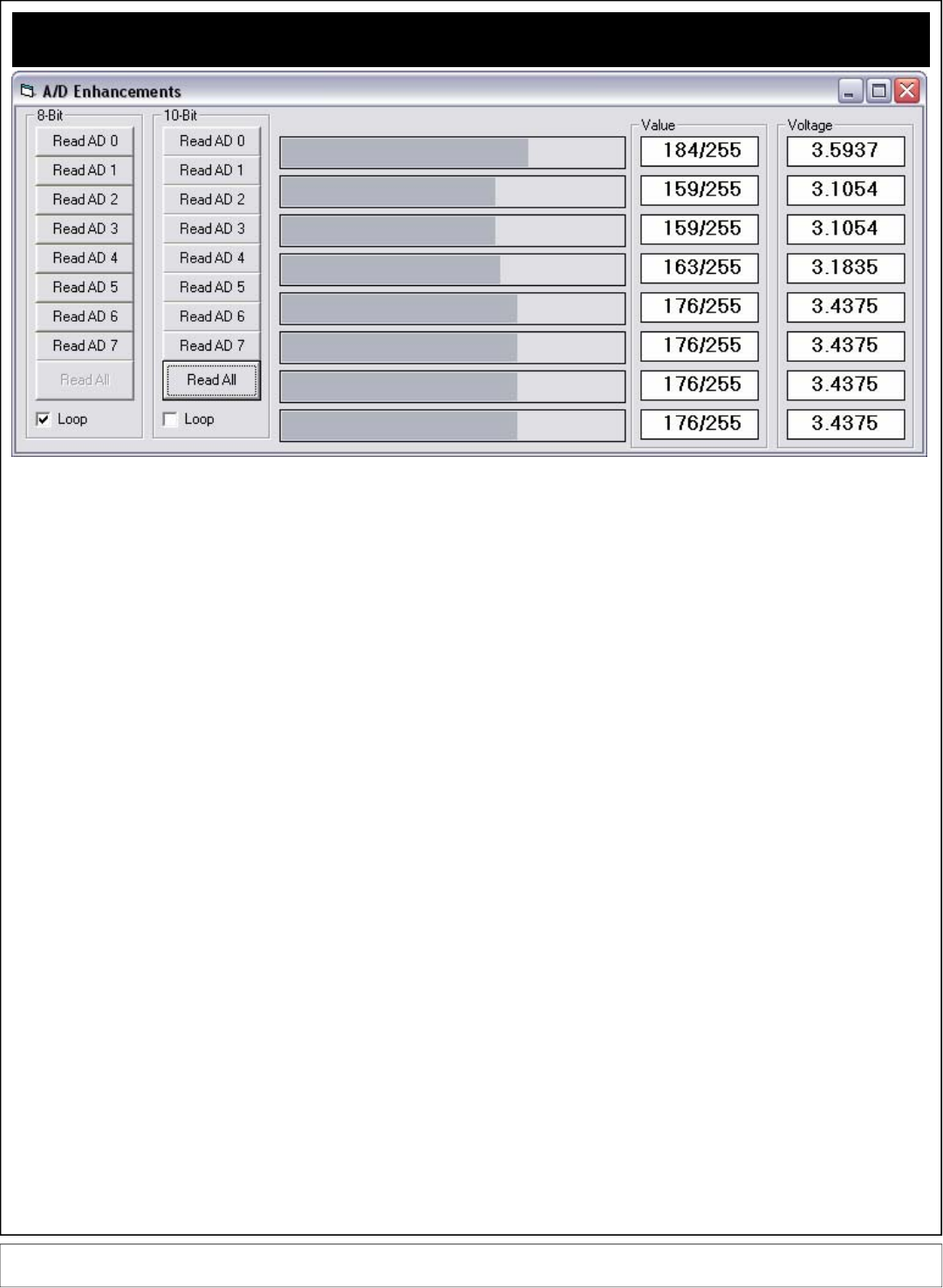
Analog to Digital Conversion Command Set
Some ProXR Series Enhanced Controllers support Analog to Digital Conversion.
Often referred to as A/D or ADC, A/D conversion is the process of converting a
voltage to a numeric value that can be read by your computer. The input chan-
nels on NCD A/D converters can support a voltage range of 0 to +5VDC. Exceed-
ing this input voltage will damage the CPU on the ProXR controller. Regardless
of the type of interface you may be using (RS-232, USB, Zigbee), the commands
found on this page will work with ALL ProXR controllers that are equipped with 8-
Channels of A/D conversion.
A/D conversion is most commonly used to read sensors, such as light and tem-
perature sensors, but can also be used to read switches, magnets, or any sensor
that provides an ON/OFF switch closure output –or– a sensor that provides a
voltage within the 0-5VDC voltage range.
NCD Enhanced controllers support 8-Bit or 10-Bit Analog to Digital Conversion. A
8-Bit A/D conversion reads a voltage from 0-5VDC and converts it to a value from
0 to 255. A 10-Bit A/D conversion reads a voltage from 0-5VDC and converts it to
a value from 0 to 1023. As you can see, a 10-Bit A/D conversion is more accu-
rate, but it also takes longer to communicate the result to the computer because it
requires two bytes to communicate a value of 0 to 1023 whereas a 8-Bit conver-
sion only requires one byte. Effectively, 8-Bit A/D conversion is twice as fast, but
10-Bit A/D conversion is 4x more accurate.
Keep in mind, the commands found on this page apply ONLY to NCD controllers
with 8-Channels of A/D conversion built in. These commands will not be proc-
essed by other controllers. The commands will are the same regardless of the
interface you are using (RS-232, USB, Zigbee).
254,150 Read 8-Bit A/D Channel 1 Returns 1 Byte 0-255
254,151 Read 8-Bit A/D Channel 2 Returns 1 Byte 0-255
254,152 Read 8-Bit A/D Channel 3 Returns 1 Byte 0-255
254,153 Read 8-Bit A/D Channel 4 Returns 1 Byte 0-255
254,154 Read 8-Bit A/D Channel 5 Returns 1 Byte 0-255
254,155 Read 8-Bit A/D Channel 6 Returns 1 Byte 0-255
254,156 Read 8-Bit A/D Channel 7 Returns 1 Byte 0-255
254,157 Read 8-Bit A/D Channel 8 Returns 1 Byte 0-255
254,158 Read 10-Bit A/D Channel 1 Returns 2 Bytes 0-1023
254,159 Read 10-Bit A/D Channel 2 Returns 2 Bytes 0-1023
254,160 Read 10-Bit A/D Channel 3 Returns 2 Bytes 0-1023
254,161 Read 10-Bit A/D Channel 4 Returns 2 Bytes 0-1023
254,162 Read 10-Bit A/D Channel 5 Returns 2 Bytes 0-1023
254,163 Read 10-Bit A/D Channel 6 Returns 2 Bytes 0-1023
254,164 Read 10-Bit A/D Channel 7 Returns 2 Bytes 0-1023
254,165 Read 10-Bit A/D Channel 8 Returns 2 Bytes 0-1023
254,166 Read 8-Bit A/D All Channels Returns 8 Bytes, Each 0-255
254,167 Read 10-Bit A/D All Channels Returns 16 Bytes, 2-Bytes
per Channel, 8 Channels, Valuing 0-1023 per Channel.
Here are some simple programming examples in VB:
254,150 Read Channel 1, 8-Bit
MSComm1.Output = Chr$(254) 'Enter Command Mode
MSComm1.Output = Chr$(150) 'Read Channel 1, 8-Bit
Value = GetData 'Read Byte from the Serial Buffer
(The controller will return a single byte from 0-255 indicating the voltage on the selected input
channel)
254,158 Read Channel 1, 10-Bit
MSComm1.Output = Chr$(254) 'Enter Command Mode
MSComm1.Output = Chr$(158) 'Read Channel 1, 10-Bit
MSB = GetData 'Read MSB Byte from the Serial Buffer
LSB = GetData 'Read MSB Byte from the Serial Buffer
Value = LSB + (MSB * 256) 'Convert Returned Data to Value from 0-1023
The controller will return two bytes indicating the voltage on the selected input channel, the first
returned value is the Most Significant Byte MSB, the second byte sent to your computer will be the
Least Significant Byte LSB. Using the formula VALUE= (LSB + (MSB * 256)), where VALUE will
equate to a numeric value from 0 to 1023. Here is a code sample:
254,166 Read All Channels, 8-Bit
MSComm1.Output = Chr$(254) 'Enter Command Mode
MSComm1.Output = Chr$(166) 'Read All Channels, 8-Bit
Channel1 = GetData 'Read Channel 1 from the Serial Buffer
Channel2 = GetData 'Read Channel 2 from the Serial Buffer
Channel3 = GetData 'Read Channel 3 from the Serial Buffer
Channel4 = GetData 'Read Channel 4 from the Serial Buffer
Channel5 = GetData 'Read Channel 5 from the Serial Buffer
Channel6 = GetData 'Read Channel 6 from the Serial Buffer
Channel7 = GetData 'Read Channel 7 from the Serial Buffer
Channel8 = GetData 'Read Channel 8 from the Serial Buffer
254,167 Read All Channels, 10-Bit
MSComm1.Output = Chr$(254) 'Enter Command Mode
MSComm1.Output = Chr$(167) 'Read All Channels, 10-Bit
For X = 1 to 8
MSB = GetData 'Read MSB Byte from the Serial Buffer
LSB = GetData 'Read MSB Byte from the Serial Buffer
Debug.Print LSB + (MSB * 256) 'Convert and Print Returned Data to Value from 0-1023
Next X
NOTICE:
GetData shown in the code above is a Function and is NOT a VB Command. GetData calls the
code shown below, used for Reading a Byte of Data from the PC Serial Buffer:
Public Function GetData() ‘Read a Byte of Data from the Controller in VB
Do ‘Start a Continuous Loop
DoEvents ‘Service Other Windows Tasks (Very Important!!!)
Until MSComm1.InBufferCount > 0 ‘Continue Loop Until a Byte of Data is Received
GetData = ASC(MSComm1.Input) ‘Read Data Byte from the Serial Port
End Function
These Command Apply ONLY to ProXR Controllers Enhanced with 8-Channels of Analog to Digital Conversion, Available with RS-232, USB,
Zigbee, Ethernet, and 802.11b Wi-Fi WLAN Interface. These commands will not be processed by the standard ProXR Series.
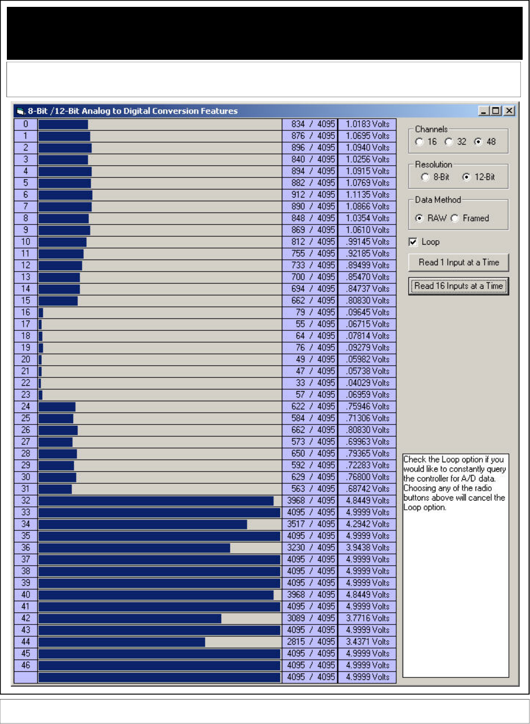
AD12 Series 12-Bit Analog to Digital Conversion
With ProXR Relay Control Command Set
These Command Apply ONLY to ProXR Controllers Enhanced with High-Resolution Analog to Digital Conversion, Available Interface Op-
tions Include RS-232 and USB. These commands will not be processed by the standard ProXR Series.
Analog to Digital Conversion is the Process of Converting a Voltage to a Number. A low voltage yields a low number while a high voltage yields a high number. The AD12PROXR Series Control-
lers allow you to read up to 48 channels of Voltages. With minimal amounts of software, it is possible to control relays based on input voltages. NCD AD Converter devices are ideally suited for
interface to light and temperature sensors, as well as buttons and switches. If you are looking to read data, evaluate the results, and control relays all with a single controller, then the
AD12PROXR series is for you.
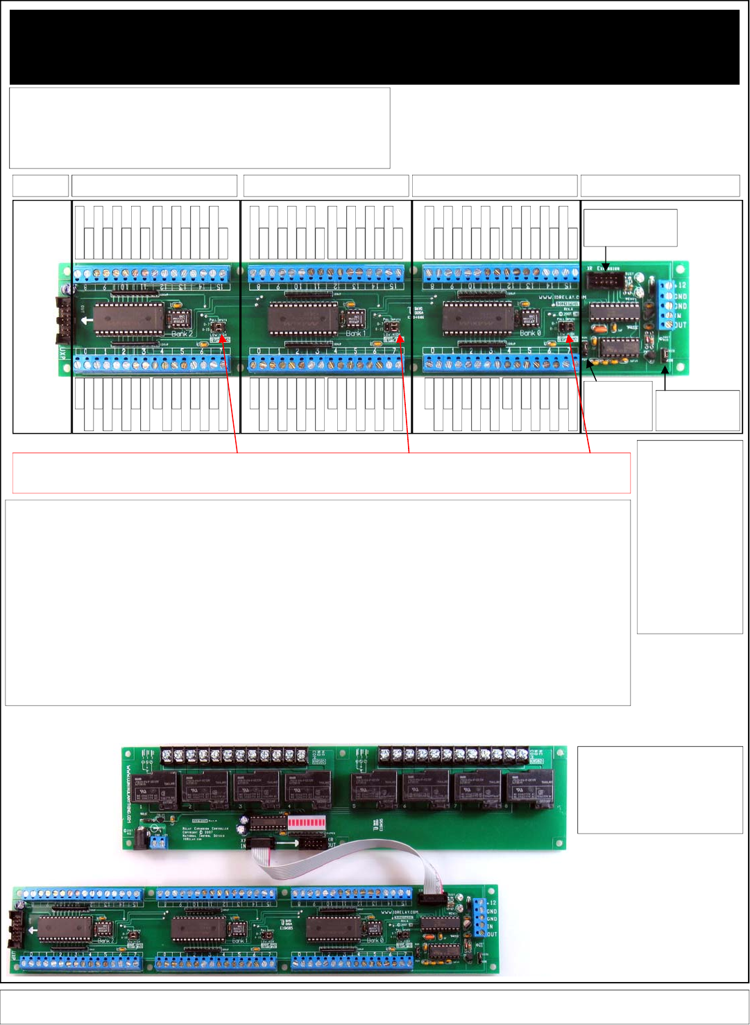
AD12 Series 12-Bit Analog to Digital Conversion
With ProXR Relay Control Command Set
These Command Apply ONLY to ProXR Controllers Enhanced with High-Resolution Analog to Digital Conversion, Available Interface Op-
tions Include RS-232 and USB. These commands will not be processed by the standard ProXR Series.
In addition to Multi-Channel High Resolu-
tion Analog to Digital Conversion, the
AD12 Series Controllers can be Expanded
to Control up to 256 External Relays.
The XR Expansion Port is compatible with
any Relay Controller that begins with the
part number XR.
BANK 0 (Also Called Device 0) BANK 1 (Also Called Device 1) BANK 2 (Also Called Device 2)
Expansion Interface (USB/RS232)
See Page 5
Of this
Manual for
Interface
Connection
Information
Control External
Relays with the XR
Expansion Port
RS232 / OC232
Jumper. Use OC232
Only when Networking
(Page 7)
PGM/RUN Jumper
Use PGM to
Change Configu-
ration Settings
ONLY
Ground
Analog Input 0
Ground
Analog Input 1
Ground
Analog Input 2
Ground
Analog Input 3
Ground
Analog Input 4
Ground
Analog Input 5
Ground
Analog Input 6
Ground
Analog Input 7
Ground
Analog Input 15
Ground
Analog Input 14
Ground
Analog Input 13
Ground
Analog Input 12
Ground
Analog Input 11
Ground
Analog Input 10
Ground
Analog Input 9
Ground
Analog Input 8
Ground
Analog Input 0
Ground
Analog Input 1
Ground
Analog Input 2
Ground
Analog Input 3
Ground
Analog Input 4
Ground
Analog Input 5
Ground
Analog Input 6
Ground
Analog Input 7
Ground
Analog Input 15
Ground
Analog Input 14
Ground
Analog Input 13
Ground
Analog Input 12
Ground
Analog Input 11
Ground
Analog Input 10
Ground
Analog Input 9
Ground
Analog Input 8
Expandable
to 48 Chan-
nels MAX.
Expansion
Not Used on
48-Channel
Version.
For 16 and 32
Channel
Version, use
Part Number
UAD1216 to
Add More
Inputs.
Pull-Up/Down Jumpers: As a general rule, Analog Inputs Should Not “Float”. An input is considered “floating” when it is disconnected or not in use. Floating inputs can affect the
analog readings on other channels. We have included Pull-Up/Down jumpers that keep all inputs quiet. When installing the “Pull Inputs” jumper in the “LOW” position, all inputs are
connected to ground through a 10K resistor. When installing the “Pull Inputs” jumper in the “High” position, all inputs are connected to +5VDC through a 10K resistor. You may also
remove the “Pull Inputs” jumper to float the inputs. Remember, do NOT Exceed 0-5VDC on ANY input. Doing so will damage the controller. Also, all grounds are Shared on this device.
LED Status Lights:
READY: This Light is RED
when Waiting for a Com-
mand. This Light turns off
when a command is in
process.
BUSY: This Light is RED
when a command is in
process and is OFF when the
device is ready for data.
USB Status Lights:
USB: Lights when Communi-
cation is Established be-
tween PC and Controller.
RX: Lights when Data is
Received from the Computer.
TX: Lights when Data is
Transmitted to the Computer.
Introduction:
The AD1216PROXR Series Controllers allow you to read analog data into the computer. These devices are ideally suited for reading thermis-
tors, photocells, thermocouples, or other sensor devices with voltage or resistive outputs. These controllers may also be used to read contact
closure devices such as switches and buttons.
The purpose of the AD1216PROXR series is to read analog data into a PC or embedded computer, and convert the voltage values to numeric
values that can be easily processed. The AD1216PROXR series support reading single inputs or groups of 16 inputs with a single request.
Both 8-Bit and 12-Bit resolutions are supported by this device. The data generated by the AD1216PROXR series is very easy to process:
When an input is at 0 volts, the controller will generate a numeric value of 0. When an input is at 5 volts, the controller will generate a numeric
value of 255 (8-Bit Resolution) or 4095 (12-Bit Resolution). When an input is at 2.5 Volts, the controller will generate a numeric value of 127 (8-
Bit Resolution) or 2047 (12-Bit Resolution).
In addition to reading inputs, this controller fully supports the ProXR command set, allowing you to activate relays externally. This is ideal for
applications that may require a light or temperature activated switch, using your computer or microcontroller to set the threshold limits.
This device is available with an RS-232 interface (fully E3C compliant), supporting baud rates up to 115.2K Baud. This device is also available
with a USB interface at a fixed baud rate of 115.2K baud.
This Page Applies to the Following Part Numbers:
AD1216PROXR RS-232 16-Channel 12-Bit A/D Analog to Digital Converter + XR Expansion Port
AD1232PROXR RS-232 32-Channel 12-Bit A/D Analog to Digital Converter + XR Expansion Port
AD1248PROXR RS-232 48-Channel 12-Bit A/D Analog to Digital Converter + XR Expansion Port
UAD1216ProXR USB 16-Channel 12-Bit A/D Analog to Digital Converter + XR Expansion Port
UAD1232ProXR USB 32-Channel 12-Bit A/D Analog to Digital Converter + XR Expansion Port
UAD1248ProXR USB 48-Channel 12-Bit A/D Analog to Digital Converter + XR Expansion Port

AD12 Series 12-Bit Analog to Digital Conversion
With ProXR Relay Control Command Set
The AD1216PROXR Series Controllers wait for a command and return data based on the command you send. Data comes back in many formats, depending on the
command that you issue to the controller. Here is a summary of the commands that can be sent to the controller. When a command is sent to the device, the device
will reply with data as shown below:
Command Function Response
254,192 Read 16 Channels at a Time, 8-Bit A/D Device Bank 0 Returns 16 Bytes
254,193 Read 16 Channels at a Time, 8-Bit A/D Device Bank 1 Returns 16 Bytes
254,194 Read 16 Channels at a Time, 8-Bit A/D Device Bank 2 Returns 16 Bytes
When the above commands are sent to the controller, the controller will respond with 16 bytes of data indicating analog values from 0 to
255 for each of the 16 channels. Data will be sent in the following order from left to right:
Channel 0, 1, 2, 3, 4, 5, 7, 8, 9, 10, 11, 12, 13, 14, 15
254,195,Channel Read Single Channel at a Time, 8-Bit A/D Device Bank 0 Returns 1 Byte of Analog Data
254,196 Read 16 Channels at a Time, 12-Bit A/D Device Bank 0 Returns 32 Bytes
254,197 Read 16 Channels at a Time, 12-Bit A/D Device Bank 1 Returns 32 Bytes
254,198 Read 16 Channels at a Time, 12-Bit A/D Device Bank 2 Returns 32 Bytes
When the above commands are sent to the controller, the controller will respond with 32 bytes of data indicating analog values from 0 to
255 for each of the 16 channels. Data will be sent in the following order from left to right:
Channel 0 LSB, 0 MSB, 1 LSB, 1 MSB, 2 LSB, 2 MSB, 3 LSB, 3 MSB, 4 LSB, 4 MSB, 5 LSB, 5 MSB, 6 LSB, 6 MSB, 7 LSB, 7 MSB, 8 LSB, 8
MSB, 9 LSB, 9 MSB, 10 LSB, 10 MSB, 11 LSB, 11 MSB, 12 LSB, 12 MSB, 13 LSB, 13 MSB, 14 LSB, 14 MSB, 15 LSB, 15 MSB.
254,199,Channel Read Single Channel at a Time, 12-Bit A/D Device Bank 0 Returns 2 Bytes LSB then MSB
254,200 Read 16 Channels at a Time, 8-Bit A/D Device Bank 0 (Packet Format) Returns 18 Bytes
254,201 Read 16 Channels at a Time, 8-Bit A/D Device Bank 1 (Packet Format) Returns 18 Bytes
254,202 Read 16 Channels at a Time, 8-Bit A/D Device Bank 2 (Packet Format) Returns 18 Bytes
When the above commands are sent to the controller, the controller will respond with 18 bytes of data indicating analog values from 0 to
255 for each of the 16 channels. Also included in the data structure is a Header Byte (254), and a Checksum Byte (which is the total
value of 254 + all 16 bytes of data). The checksum byte only contains the lower 8 bits of data. Data will be sent in the following order
from left to right:
Header Byte 254, Channel 0, 1, 2, 3, 4, 5, 7, 8, 9, 10, 11, 12, 13, 14, 15, Checksum Value
254,203,Channel Read Single Channel at a Time, 8-Bit A/D Device Bank 1 Returns 1 Byte of Analog Data
254,204 Read 16 Channels at a Time, 12-Bit A/D Device Bank 0 (Packet Format) Returns 34 Bytes
254,205 Read 16 Channels at a Time, 12-Bit A/D Device Bank 1 (Packet Format) Returns 34 Bytes
254,206 Read 16 Channels at a Time, 12-Bit A/D Device Bank 2 (Packet Format) Returns 34 Bytes
When the above commands are sent to the controller, the controller will respond with 34 bytes of data indicating analog values from 0 to
4095 for each of the 16 channels. Also included in the data structure is a Header Byte (254), and a Checksum Byte (which is the total
value of 254 + all 16 bytes of data). Data will be sent in the following order from left to right:
Header Byte 254, Channel 0 LSB, 0 MSB, 1 LSB, 1 MSB, 2 LSB, 2 MSB, 3 LSB, 3 MSB, 4 LSB, 4 MSB, 5 LSB, 5 MSB, 6 LSB, 6 MSB, 7 LSB,
7 MSB, 8 LSB, 8 MSB, 9 LSB, 9 MSB, 10 LSB, 10 MSB, 11 LSB, 11 MSB, 12 LSB, 12 MSB, 13 LSB, 13 MSB, 14 LSB, 14 MSB, 15 LSB, 15
MSB, Checksum Value.
254,207,Channel Read Single Channel at a Time, 12-Bit A/D Device Bank 1 Returns 2 Bytes LSB then MSB
254,208,Channel Read Single Channel at a Time, 8-Bit A/D Device Bank 2 Returns 1 Byte of Analog Data
254,209,Channel Read Single Channel at a Time, 12-Bit A/D Device Bank 2 Returns 1 Byte of Analog Data
Channel = Value Between 0 and 15
LSB = Least Significant byte When data greater than 8 bits must be sent, 2 bytes are required, LSB and MSB.
MSB = Most Significant byte The value of these two bytes is computed with back into a integer value.
Value = LSB + (MSB * 256) Note: This formula is used to convert LSB/MSB 12 bit values to integer values 0-4095.
Checksum = (254 + All Data) And 255 Note: “And” is a mathematical function supported by most programming languages
8-Bit Resolution = 5VDC Divided By 256 Steps = .01953125 Volts per Step
12-Bit Resolution = 5VDC Divided by 4096 Steps = .001220703125 Volts per Step
NOTE: Incoming Signals are degraded by approximately 100 ohms before analog to digital conversion process.
These Command Apply ONLY to ProXR Controllers Enhanced with High-Resolution Analog to Digital Conversion, Available Interface Op-
tions Include RS-232 and USB. These commands will not be processed by the standard ProXR Series.

AD12 Series 12-Bit Analog to Digital Conversion
With ProXR Relay Control Command Set
These Command Apply ONLY to ProXR Controllers Enhanced with High-Resolution Analog to Digital Conversion, Available Interface Op-
tions Include RS-232 and USB. These commands will not be processed by the standard ProXR Series.
On this page, we will demonstrate a practical example for handling the incoming
data from the AD1216PROXR series controllers. The programming examples
shown on this page were written in Visual Basic 6 Professional. The “GetData”
and “GetData2” functions are used to read data from the controller. This function
is shown in greater detail at the bottom left of this page.
254,195,1 Read Channel 1, 8-Bit
MSComm1.Output = Chr$(254) 'Enter Command Mode
MSComm1.Output = Chr$(195) 'Read Single Channel 8-Bit
MSComm1.Output = Chr$(1) 'Read Channel 1
Value = GetData 'Read Byte from the Serial Buffer
(The controller will return a single byte from 0-255 indicating the voltage on the selected input
channel)
254,199,1 Read Channel 1, 12-Bit
MSComm1.Output = Chr$(254) 'Enter Command Mode
MSComm1.Output = Chr$(199) 'Read Single Channel 12-Bit
MSComm1.Output = Chr$(1) 'Read Channel 1
MSB = GetData 'Read MSB Byte from the Serial Buffer
LSB = GetData 'Read MSB Byte from the Serial Buffer
Value = LSB + (MSB * 256) 'Convert Returned Data to Value from 0-4095
The controller will return two bytes indicating the voltage on the selected input channel, the first
returned value is the Most Significant Byte MSB, the second byte sent to your computer will be the
Least Significant Byte LSB. Using the formula VALUE= (LSB + (MSB * 256)), where VALUE will
equate to a numeric value from 0 to 4095. Here is a code sample:
254,192 Read All 16 Channels on Bank 0, 8-Bit
MSComm1.Output = Chr$(254) 'Enter Command Mode
MSComm1.Output = Chr$(192) 'Read All 16 Channels, Bank 0, 8-Bit
Channel1 = GetData 'Read Channel 1 from the Serial Buffer
Channel2 = GetData 'Read Channel 2 from the Serial Buffer
Channel3 = GetData 'Read Channel 3 from the Serial Buffer
…………...
Channel16 = GetData 'Read Channel 16 from the Serial Buffer
254,196 Read All Channels on Bank 0, 12-Bit
MSComm1.Output = Chr$(254) 'Enter Command Mode
MSComm1.Output = Chr$(196) 'Read All Channels, 12-Bit
For X = 1 to 16
MSB = GetData 'Read MSB Byte from the Serial Buffer
LSB = GetData 'Read MSB Byte from the Serial Buffer
Debug.Print LSB + (MSB * 256) 'Convert and Print Returned Data to Value from 0-4095
Next X
NOTICE:
GetData shown in the code above is a Function and is NOT a VB Command. GetData calls the
code shown below, used for Reading a Byte of Data from the PC Serial Buffer:
Public Function GetData() ‘Read a Byte of Data from the Controller in VB
Do ‘Start a Continuous Loop
DoEvents ‘Service Other Windows Tasks (Very Important!!!)
Until MSComm1.InBufferCount > 0 ‘Continue Loop Until a Byte of Data is Received
GetData = ASC(MSComm1.Input) ‘Read Data Byte from the Serial Port
End Function
NOTICE:
GetData2 is slightly smarter than the GetData function. This routine times out if data is not received
within 4000 counts. This value can be increased for longer timeouts.
Public Function GetData2()
GetData2 = -1
TT = 0
Do
DoEvents
TT = TT + 1
If TT > 4000 Then Exit Function
Loop Until MSComm1.InBufferCount > 0
GetData2 = Asc(MSComm1.Input)
End Function
The AD1216PROXR Series Controllers are capable of generating packetized data
to help insure error free communications. These data packets are “framed” with a
header byte and a footer checksum. When a packet is received, it is analyzed to
make sure all data bytes are valid BEFORE it is displayed or processed by the
user. If the data packet is invalid, a new data packet will be gathered from the
controller. Here is a example the processes a data packet from the controller:
The following code sets up a buffer array and a label to restart the routine
Dim Buffer(32) As Integer
Restart:
The following code requests data from the controller (16-Channels 12-Bit):
MSComm1.Output = Chr$(254) 'Enter Command Mode
MSComm1.Output = Chr$(204) 'Read 16-Channel 12-Bit with Packets
The following code gathers data from the controller:
CKSUM = GetData2 'Get LSB from Controller
If CKSum <> 254 then Restart 'Make Sure Header is Received and stored as Checksum
For Channel = 0 To 15 'Count Through All 16 Channels
LSB = GetData2 'Get LSB from Controller
MSB = GetData2 'Get MSB from Controller
If MSB <> -1 And LSB <> -1 Then 'If Data Does Not timeout
Buffer((Channel * 2)) = LSB 'Store LSB
Buffer((Channel * 2) + 1) = MSB 'Store MSB
CKSUM = CKSUM + LSB 'Add LSB to Checksum Value
CKSUM = CKSUM + MSB 'Add MSB to Checksum Value
End If
Next Channel
Gather Hardware and Software Checksums for Comaprison:
HW_Cksum = GetData2 'Store the Hardware Checksum
CKSUM = (CKSUM And 255) 'Compute Software Checksum
The following code executes if the Data Packet is Validated
If HW_Cksum = CKSUM Then 'If the Checksums Match
Debug.Print "CK ok"
At this point, the checksums are validated and data can be displayed or processed.
Else
Debug.Print "CK ERROR"
At this point, the checksums are not equal, new data should be gathered.
End If
Goto Restart
Here is another version that works with 8-bit A/D data:
The following code sets up a buffer array and a label to restart the routine
Dim Buffer(32) As Integer
Restart:
The following code requests data from the controller (16-Channels 12-Bit):
MSComm1.Output = Chr$(254) 'Enter Command Mode
MSComm1.Output = Chr$(200) 'Read 16-Channel 12-Bit with Packets
The following code gathers data from the controller:
CKSUM = GetData2 'Get LSB from Controller
If CKSum <> 254 then Restart 'Make Sure Header is Received and stored as Checksum
For Channel = 0 To 15 'Count Through All 16 Channels
Bytes = GetData2 'Get Analog Data Byte from Controller
If Bytes <> -1 Then 'If Data Does Not timeout
Buffer(Channel) = Bytes 'Store Bytes
CKSUM = CKSUM + Bytes 'Add LSB to Checksum Value
End If
Next Channel
Gather Hardware and Software Checksums for Comaprison:
HW_Cksum = GetData2 'Store the Hardware Checksum
CKSUM = (CKSUM And 255) 'Compute Software Checksum
The following code executes if the Data Packet is Validated
If HW_Cksum = CKSUM Then 'If the Checksums Match
Debug.Print "CK ok"
At this point, the checksums are validated and data can be displayed or processed.
Else
Debug.Print "CK ERROR"
At this point, the checksums are not equal, new data should be gathered.
End If
Goto Restart
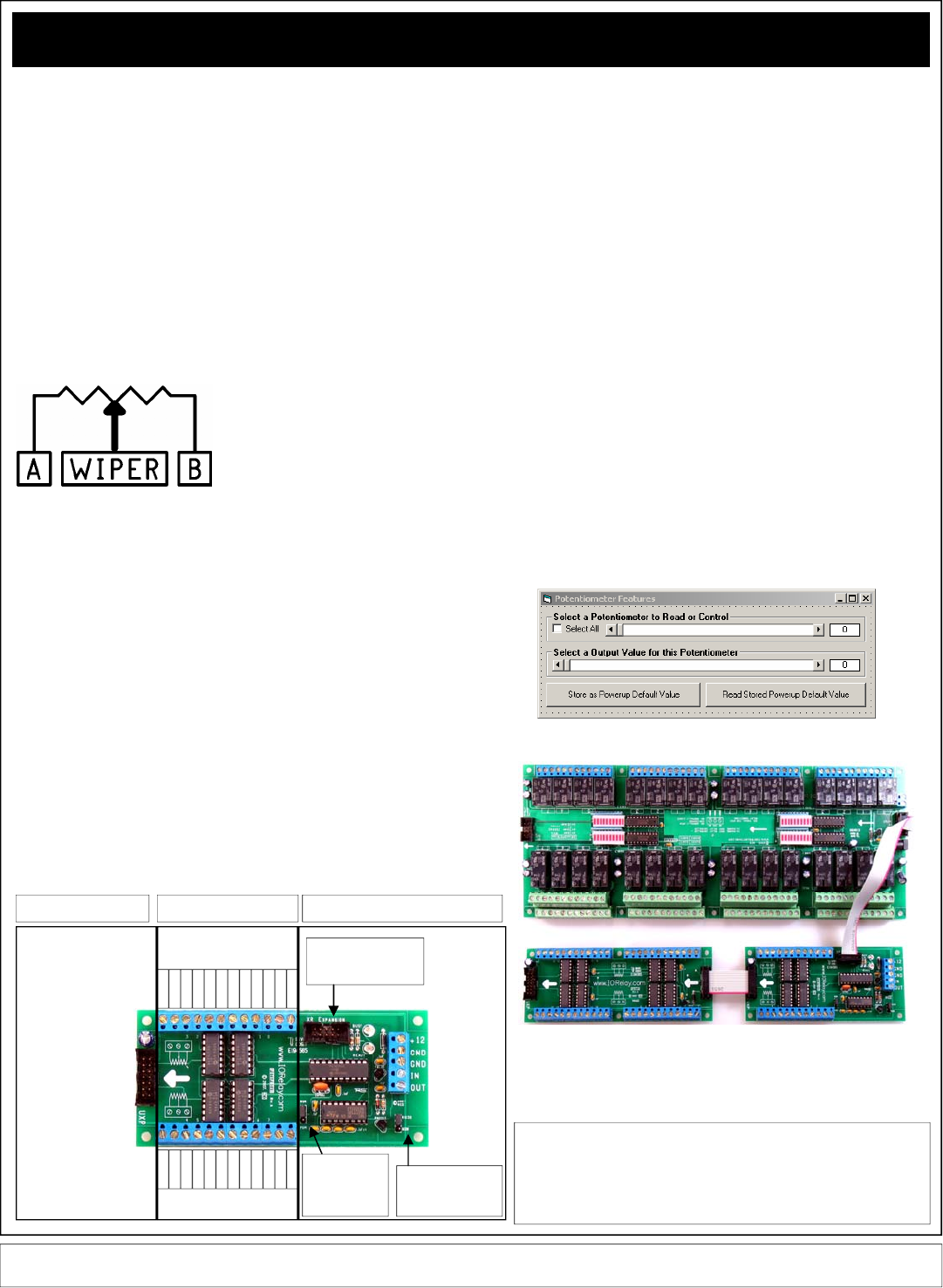
Potentiometer (Programmable Resistor) Commands
Some ProXR Series Enhanced Controllers support control of up to 256 potenti-
ometers. A potentiometer is a variable resistor, capable of changing resistance
under software control. Programmable potentiometers are ideal for making com-
puter controlled mixers and audio/video mixing devices, as well as light dimmers
and motor speed controllers. The POT and UPOT series controllers offer RS-232
and USB controlled potentiometers, and are ideally suited for integration into
various types of test instruments, programmable amplifiers, programmable power
supplies, and anything else that can benefit by software controlled resistance
variation. As a general rule, potentiometer devices often require external circuitry.
For instance, it is not possible to control the brightness of a light bulb directly or
the speed of a motor without some additional electronics.
Potentiometer controllers are available with 10K, 50K and 100K programmable
potentiometers. It is possible to set the power-up default state of the first 48
potentiometers. It is also possible to control each potentiometer in 256 steps,
allowing fine adjustments under software control. You can control up to 256
potentiometers under software control, you can control each individually or all
simultaneously. In addition to potentiometer control the POT and UPOT series
controllers include the ProXR command set, allowing you to plug in up to 256
relays into the expansion port.
Potentiometers have 3 Connections: A,
Wiper, and B. When a low value is sent to
the controller, the wiper moves closer to A,
decreasing the resistance between A and
the wiper (increasing the resistance between
the wiper and B). When a high value is sent
to the controller, the wiper moves closer to
B, decreasing the resistance between the
wiper and B (increasing the resistance between the wiper and A). The first 48
channels of wiper values can be set to a power-up default state. It is possible to
set the wipers on all outputs individually or simultaneously.
254,170, Pot, Value Set One Potentiometer to a Value
This Command Sets the wiper position of the selected potentiometer to a selected
value. POT has a valid value of 0-255, Value has a valid range of 0-255. A Low
value move the wiper closer to A. A high value moves the wiper closer to B.
MSComm1.Output = Chr$(254) 'Enter Command Mode
MSComm1.Output = Chr$(170) 'Set Potentiometer Value of a Single Output Channel
MSComm1.Output = Chr$(0) 'Select a Potentiometer to Control
MSComm1.Output = Chr$(128) 'Set the Wiper to Mid Position
Value = GetData 'Read Byte from the Serial Buffer
(When Reporting Mode is ON, controller will send ASCII Code 85 to Acknowledge this command)
254,171, Value Set All Potentiometers to a Value
This Command Sets All wiper positions of all potentiometers to a selected value.
Value has a valid range of 0-255. A Low value move the wiper closer to A. A
high value moves the wiper closer to B.
MSComm1.Output = Chr$(254) 'Enter Command Mode
MSComm1.Output = Chr$(171) 'Set All Potentiometer Values
MSComm1.Output = Chr$(255) 'Set All Wipers Close to Position B
Value = GetData 'Read Byte from the Serial Buffer
(When Reporting Mode is ON, controller will send ASCII Code 85 to Acknowledge this command)
254,172, Pot, Value Store One Potentiometer Startup Value
This Command stores a Powerup Default Wiper Position for the Selected Potenti-
ometer. Pot has a valid range of 0 to 47. Value has a valid range of 0-255. A
Low value move the wiper closer to A. A high value moves the wiper closer to B.
MSComm1.Output = Chr$(254) 'Enter Command Mode
MSComm1.Output = Chr$(172) 'Set Potentiometer Value of a Single Output Channel
MSComm1.Output = Chr$(0) 'Select a Potentiometer to Store (Maximum 47)
MSComm1.Output = Chr$(128) 'Store Wiper Startup Position to Mid Position
Value = GetData 'Read Byte from the Serial Buffer
(When Reporting Mode is ON, controller will send ASCII Code 85 to Acknowledge this command)
254,173, Pot Read Stored Potentiometer Startup Value
This Command reads the Powerup Default Wiper Position for the Selected Poten-
tiometer. Pot has a valid range of 0 to 47. This command returns a single byte of
data indicating the powerup default Wiper position of the selected potentiometer.
MSComm1.Output = Chr$(254) 'Enter Command Mode
MSComm1.Output = Chr$(173) 'Set Potentiometer Value of a Single Output Channel
MSComm1.Output = Chr$(0) 'Select a Potentiometer to Read (Maximum 47)
Value = GetData 'Read Byte from the Serial Buffer
(The controller will return a single byte from 0-255 indicating the Default Powerup Wiper Position for
the Selected Channel)
NOTICE:
GetData shown in the code above is a Function and is NOT a VB Command. GetData calls the
code shown below, used for Reading a Byte of Data from the PC Serial Buffer:
Public Function GetData() ‘Read a Byte of Data from the Controller in VB
Do ‘Start a Continuous Loop
DoEvents ‘Service Other Windows Tasks (Very Important!!!)
Until MSComm1.InBufferCount > 0 ‘Continue Loop Until a Byte of Data is Received
GetData = ASC(MSComm1.Input) ‘Read Data Byte from the Serial Port
End Function
Our ProXR Software provides you with a simple window to test these functions.
All ProXR Series Controllers can be Expanded to Control 256 Relays. This Potentiometer
Device is Capable of Controlling a total of 256 Potentiometer Outputs.
These Command Apply ONLY to ProXR Controllers Enhanced with Potentiometer Outputs, Available with RS-232 and USB Interface.
These commands will not be processed by the standard ProXR Series.
Pot 4 B
Pot 4 A
Pot 4 W
Pot 5 A
Pot 5 W
Pot 5 B
Pot 6 A
Pot 6 W
Pot 6 B
Pot 7 A
Pot 7 W
Pot 7 B
Pot 0 B
Pot 0 A
Pot 0 W
Pot 1 A
Pot 1 W
Pot 1 B
Pot 2 A
Pot 2 W
Pot 2 B
Pot 3 A
Pot 3 W
Pot 3 B
Interface (USB/RS232)
See Page 5
Of this
Manual for
Interface
Connection
Information
Control External
Relays with the XR
Expansion Port
RS232 / OC232
Jumper. Use OC232
Only when Networking
(Page 7)
PGM/RUN Jumper
Use PGM to
Change Configu-
ration Settings
ONLY
POT Interface Expansion
Use Part Number
UPOT16 to Expand
up to 256 Potenti-
ometer Outputs.
This expansion port
is not compatible
with other expansion
devices.
This Page Applies to the Following Part Numbers:
POT8ProXR RS-232 8-Channel Programmable Potentiometer + XR Expansion Port
POT16ProXR RS-232 16-Channel Programmable Potentiometer + XR Expansion Port
POT24ProXR RS-232 24-Channel Programmable Potentiometer + XR Expansion Port
UPOT8ProXR USB 8-Channel Programmable Potentiometer + XR Expansion Port
UPOT16ProXR USB 16-Channel Programmable Potentiometer + XR Expansion Port
UPOT24ProXR USB 24-Channel Programmable Potentiometer + XR Expansion Port
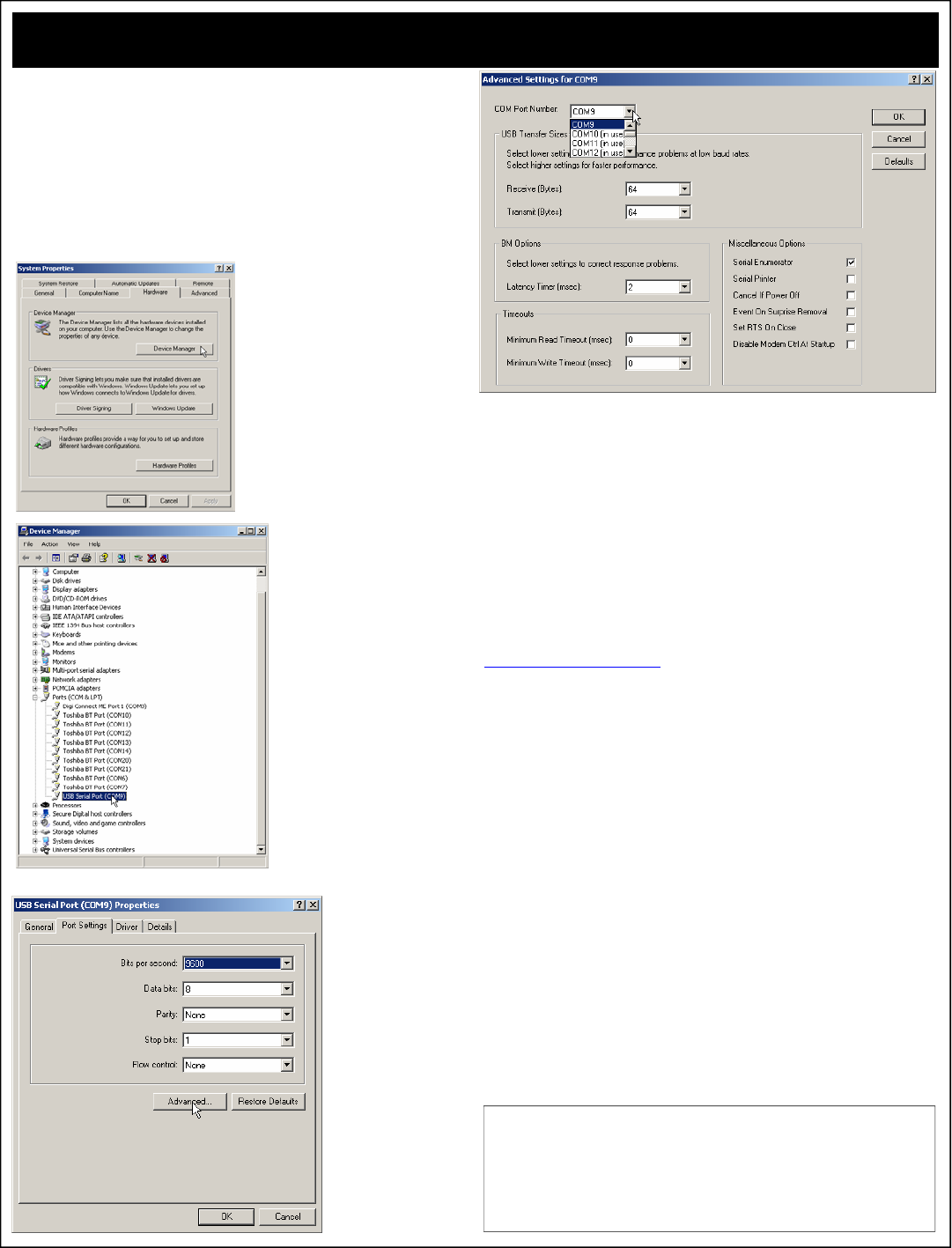
USB Speed Optimization:
Go Faster...
The ProXR Series Enhanced Controllers Equipped with a USB Interface are
shipped with a variety of parameters that are “safe” for all computers to ensure
compatibility. There are a few options that can be configured to significantly
increase communication speed between the device and the computer. This guide
shows you how to optimize communication speed for better performance. The
settings shown work on most computers without any problems.
Step 1:
Click the “Start” button in Windows and select “Control Panels”.
Step 2:
Select the “System” control panel.
Step 3:
Select the “Hardware” tab (shown be-
low), and then click “Device Manager”.
Step 4:
Navigate to the USB Serial Port for
the NCD Device you wish to opti-
mize. And Right Click.
Step 5:
Click on the “Port Set-
tings” tab and click the
“Advanced” button.
Step 6:
You can assign a different COM port to the USB device by selecting a New COM
port in the “COM Port Number” dropdown box.
Step 7:
Optimization. Set the Receive and Transmit Bytes to 64. Set the Latency Timer
to 2 milliseconds. Make sure all other parameters match the parameters shown
above and click “OK”.
Next, it would be a good idea to unplug the USB device and wait a few seconds.
Plug the device back in and follow these steps again to make sure the parameters
were properly configured for the USB driver. Once you have verified all settings,
you have successfully optimized the USB driver and will notice a significant in-
crease in communication speed. However, further speed increases are still possi-
ble. The steps outlined above only configure the USB driver for optimal speed.
Now it is time to optimize the USB device for optimal speed.
Increasing the Speed of the USB Device:
Download our “ProXR Software” and install it on your computer.
Run our ProXR software on your computer and click the yellow button at the
bottom that is labeled “Advanced Feature Settings”.
This will open the settings shown on Page 24 of this manual.
Reduce the “Serial Timing” parameter to a value from 20-35 and store the setting
into the controller. You will need to change the Program/Run jumper to “Program”
to store your settings. USB devices allow you to change this jumper without
power cycling the controller. However, you should return the jumper to the “Run”
position after settings have been stored.
Next, exit the ProXR software and unplug the USB device.
Next, reconnect the USB device to your computer. Your device should now be
optimized, though further speed enhancements may be possible by further reduc-
ing the “Serial Timing” parameter. The optimal setting will vary from computer to
computer. We achieved reliable communications with a value of 20, but some
computers may be able to handle lower settings. This setting affects the speed of
data being sent from the device to the computer. The device is easily capable of
outrunning your computer. Reducing this parameter reduces the delay between
data bytes sent to your PC. Experimentation is in order, but keep in mind, com-
mands that request more than a single byte of data from the USB device may be
adversely affected by this command. Returning the device to configuration mode
forces the device to a safe speed, regardless of your settings. This will prevent a
permanent loss of communications.
NCD USB Devices mount as a COM port on your computer. Your
software should speak to the device using the COM port that is
mounted by the device. NCD devices use a fixed data rate of
115.2K Baud, 8 data bits, 1 stop bit, No Parity. The settings
shown at left will have no bearing on your software, your soft-
ware will override the settings shown, so don’t worry about
changing the default baud rate of the driver.
