Controlled Electronic Management Systems S610MSCRM S610MSCRM RFID multi smart card reader module User Manual
Controlled Electronic Management Systems Ltd S610MSCRM RFID multi smart card reader module
UserManual.wiki
>
Controlled Electronic Management Systems
>
S610MSCRM User Manual
User manual
Navigation menu
Upload a User Manual
Namespaces
Wiki Guide
HTML
PDF
Info
Views
User Manual
Discussion / Help
Navigation
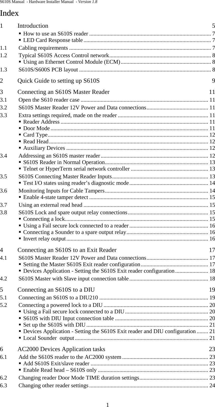
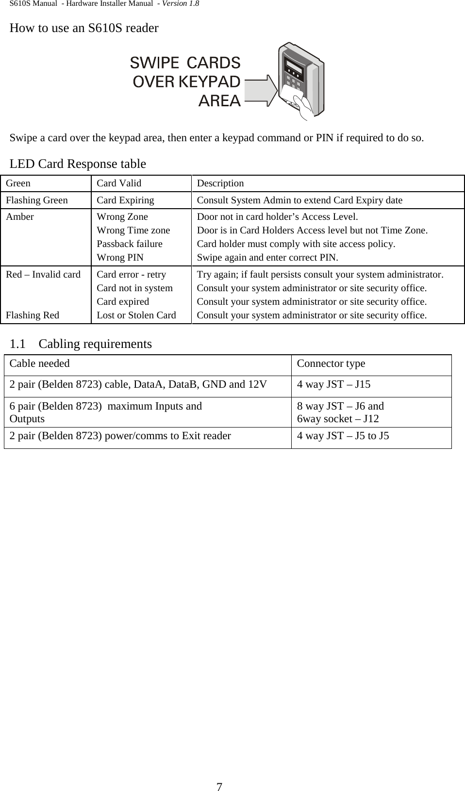
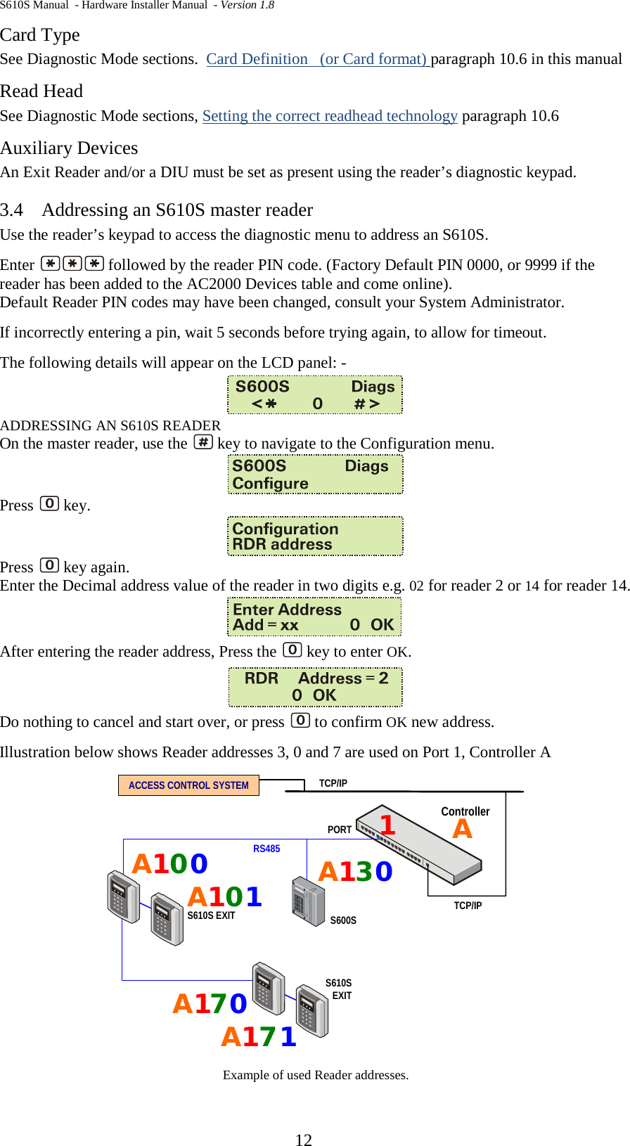
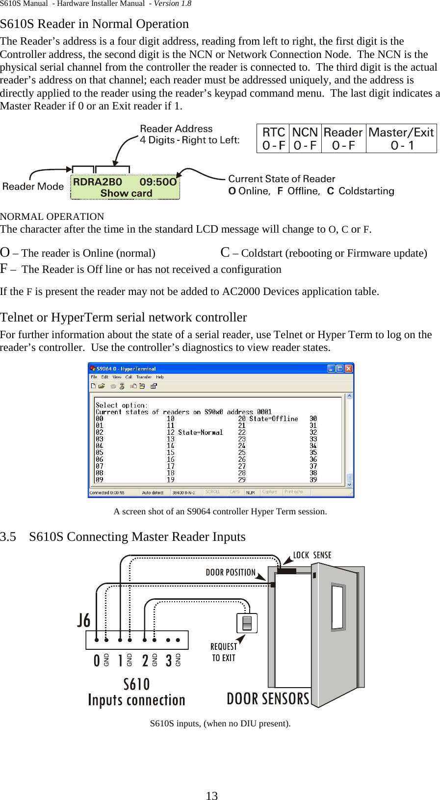
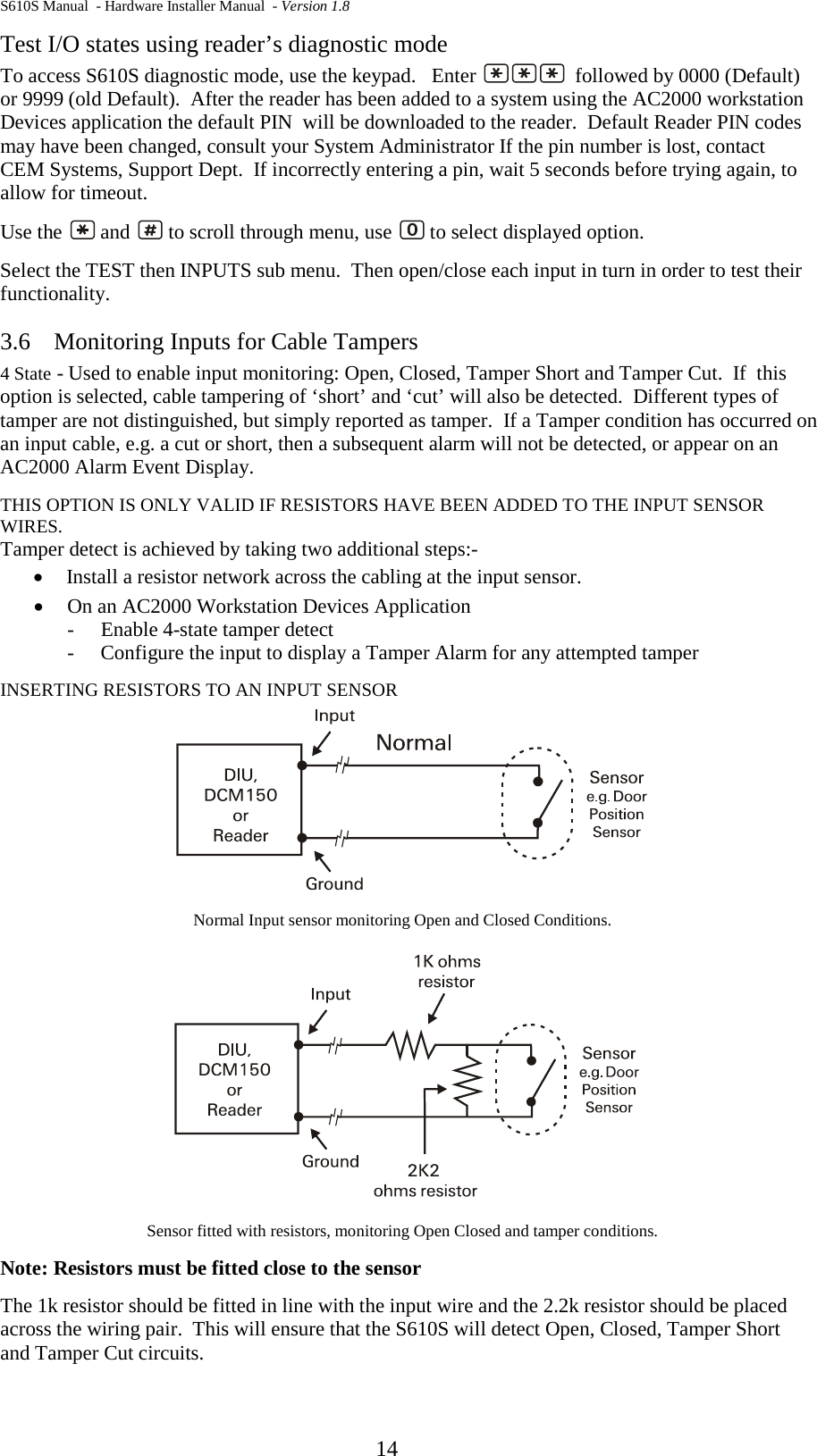
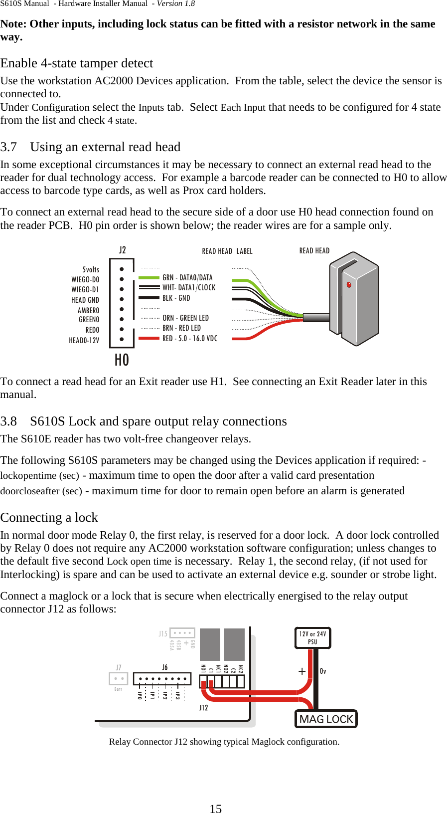
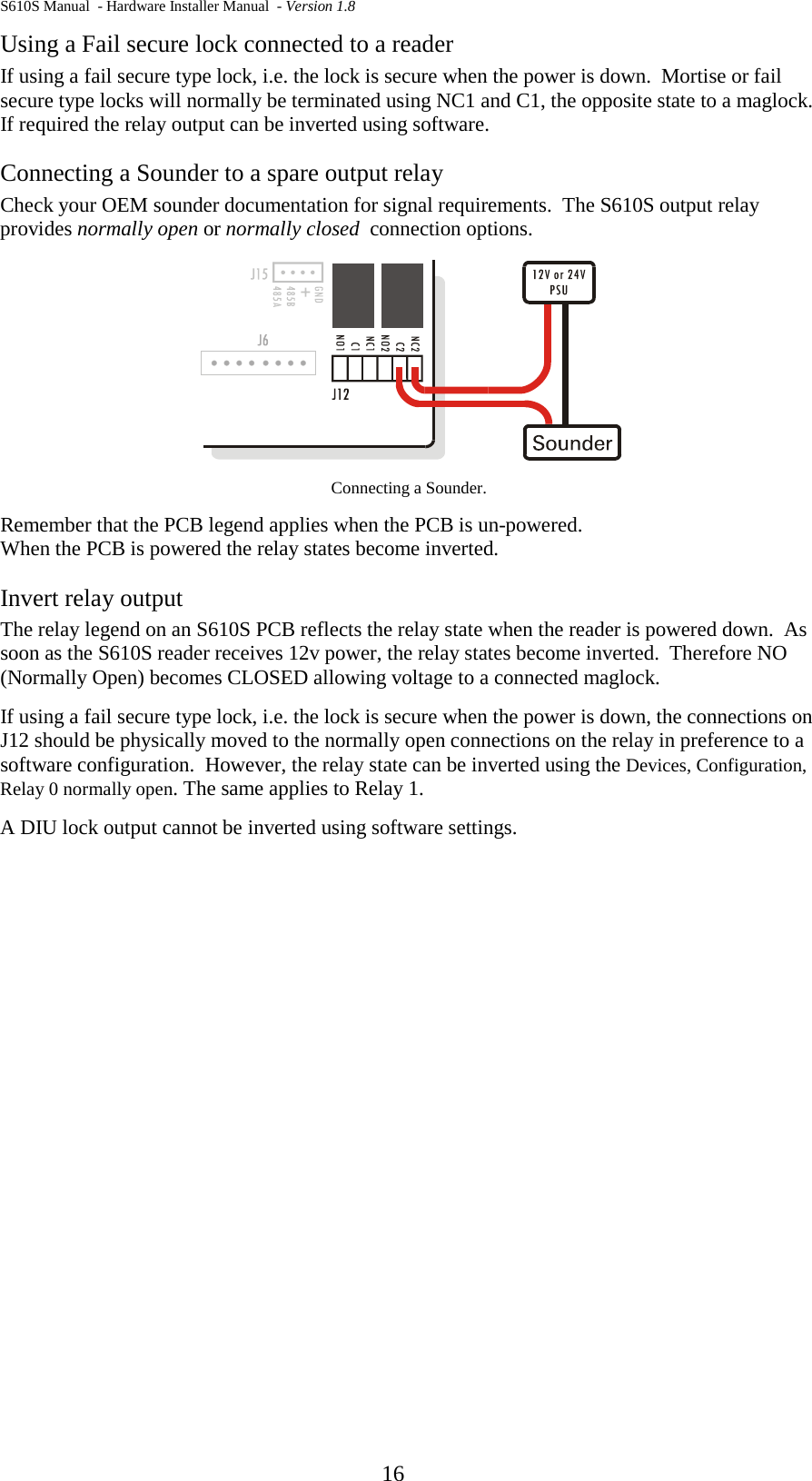
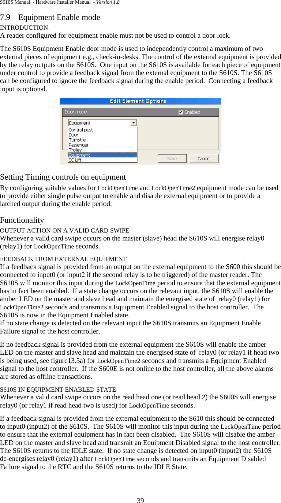
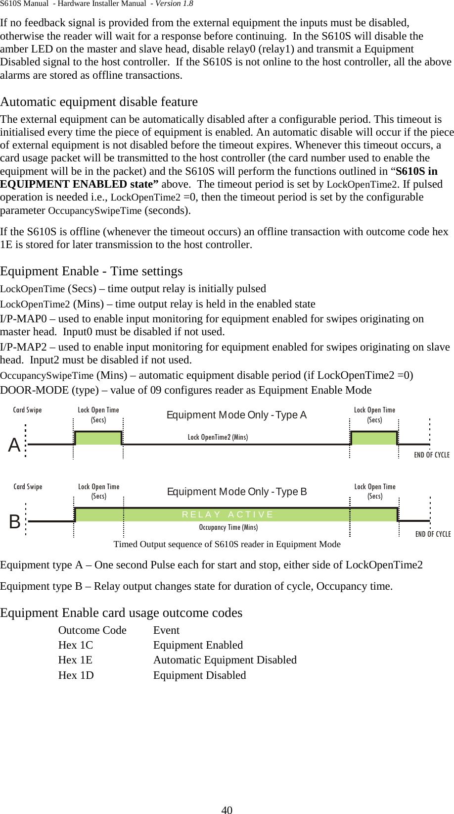
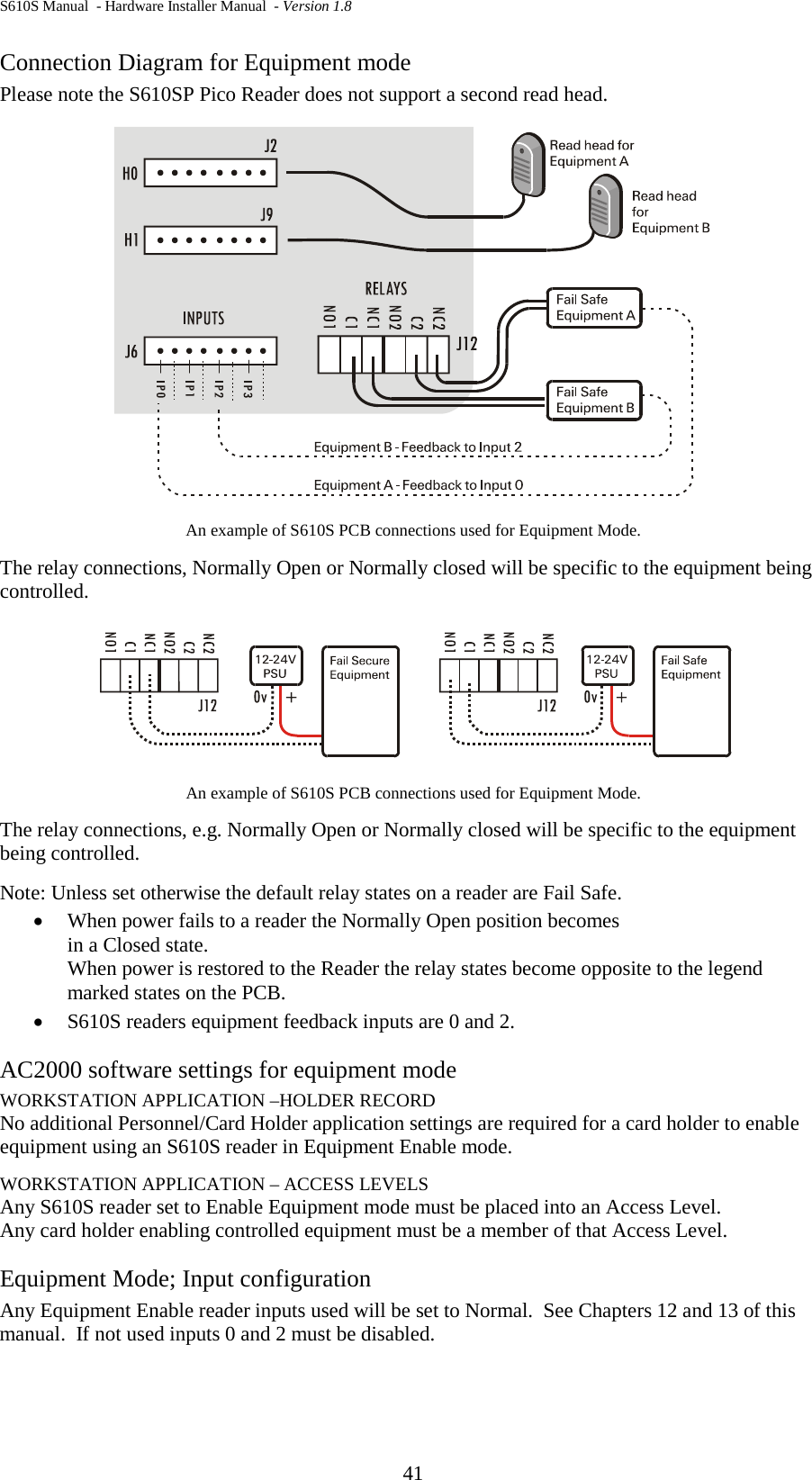
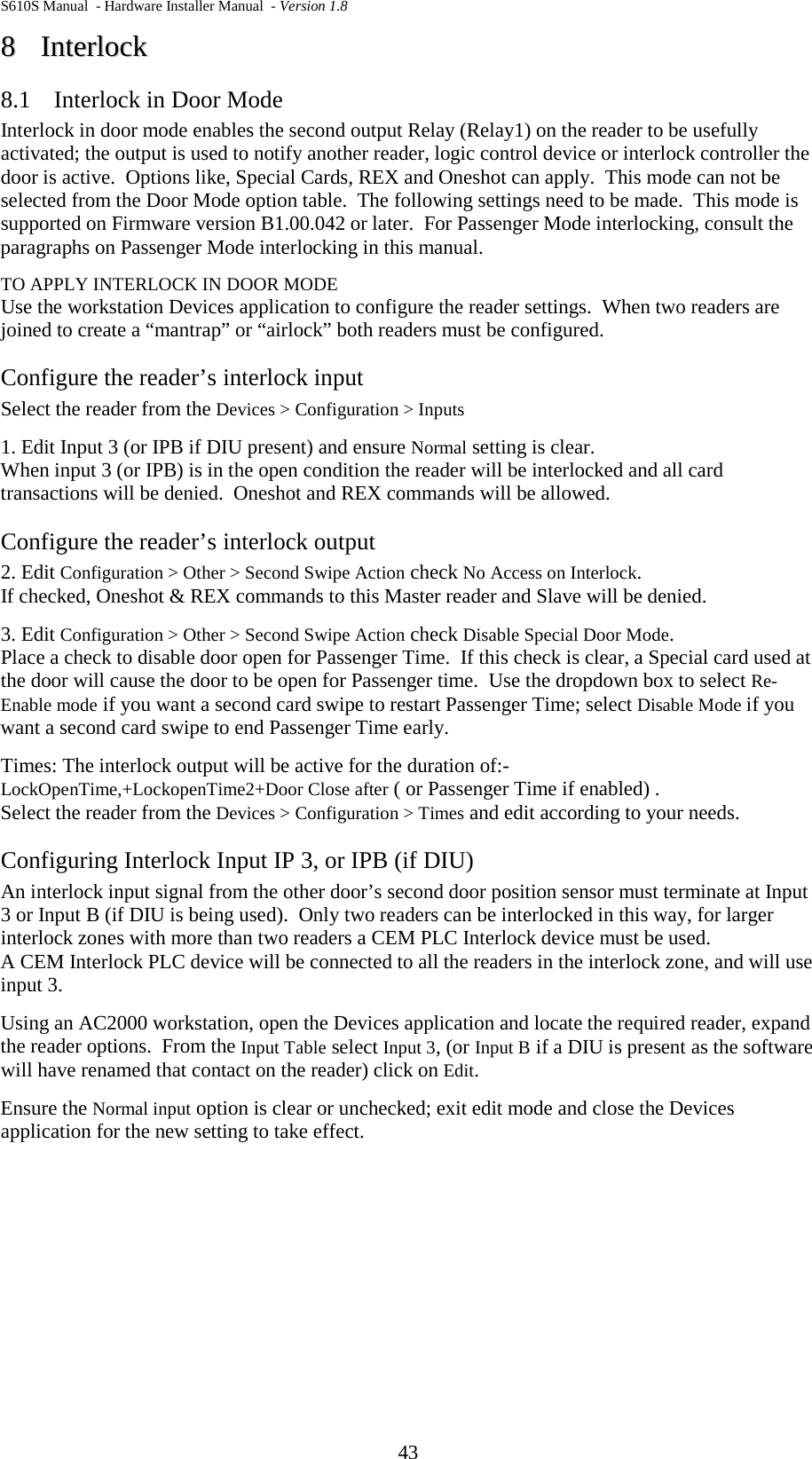
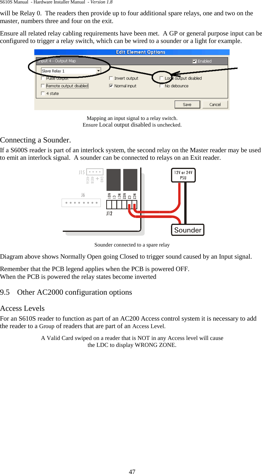
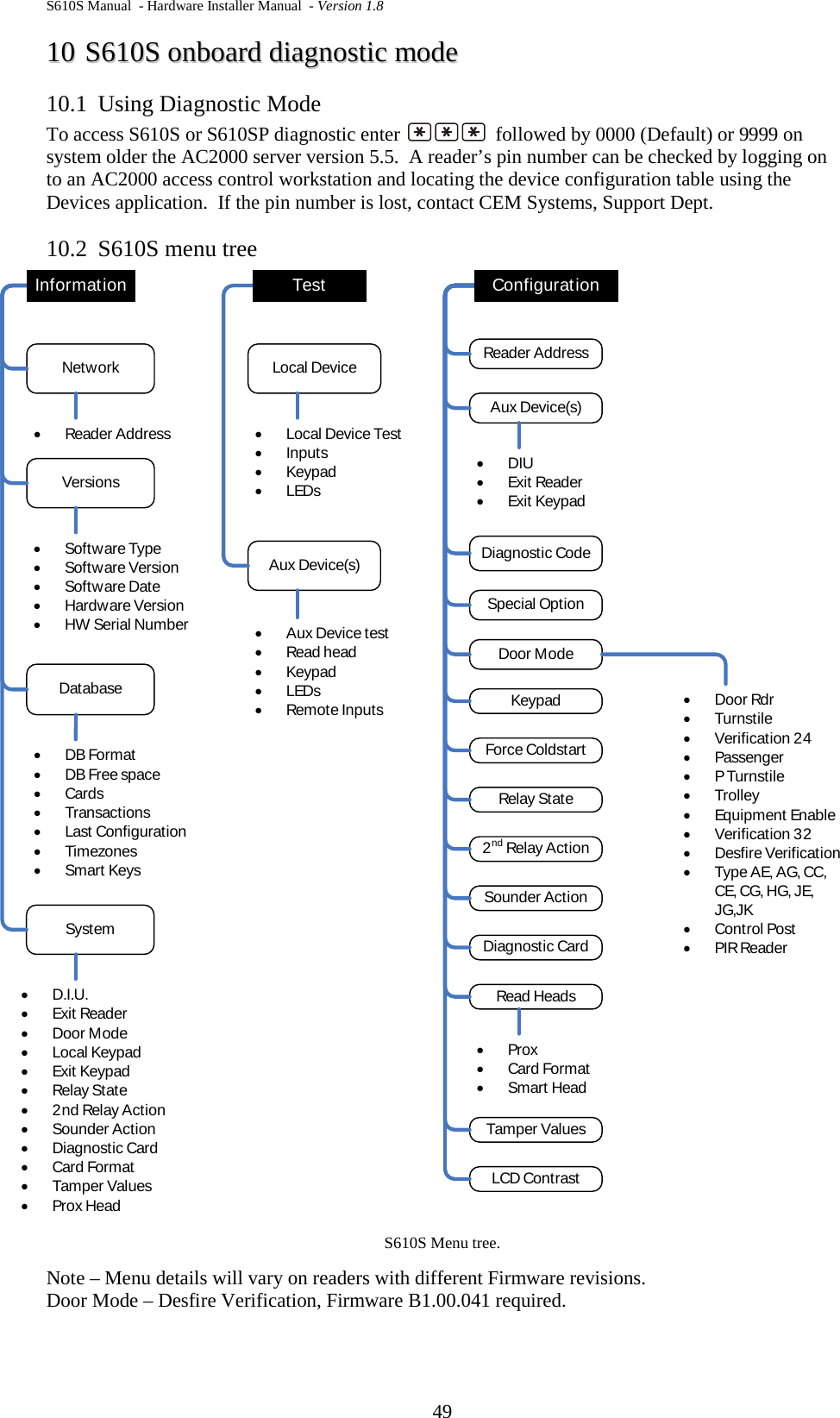
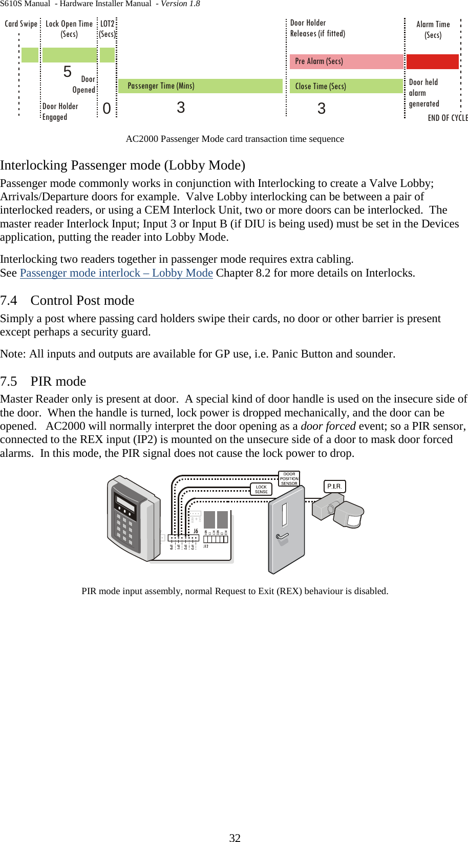
![S610S Manual - Hardware Installer Manual - Version 1.8 31 7.1 Door mode The most common mode for access control readers; on presentation of a valid card, access is granted. Open AC2000 Devices application; select the reader from the Overview table. From the Current configuration table select Door Mode and click Edit, select Door and Save. See also Interlock in Door mode, Interlock chapter in this manual. 7.2 Verification 24, Verification 32 Verification mode can be used to display cards embedded numbers on the reader’s LCD. Reader address must be15, otherwise only a Card Read message is displayed. Swiped card transactions are not stored on the AC2000 system. All compatible cards will be read and the card number and site code displayed. Verification mode is used on Validation readers. For more information on card validation, consult the CEM AC2000 System Guide, or the S610S validation reader Quick Guide available from the CEM website. Desfire Verification As above, but only applies to Desfire technology. The Mifare Desfire contactless smart cards operate in the 13.56 MHz frequency range with read/write capability. The Desfire card type uses encryption. Currently only supported by the S610S reader model. Verification mode is used on Validation readers. Contact CEM for more information. Desfire verification is not supported in the current firmware version B1.00.049. Encrypted verification – Mifare Finch Custom mode: Please contact CEM for more details. Card Number is transmitted from the S600s Reader to the Workstation as an encrypted 6 characters (24 bit) or 8 characters. 32 bit Encrypted Verification mode is activated by choosing [ENCRYPTED VER 32] door mode. When the Reader address is set to 8 to15, Encoded 8 Characters will be displayed on S600s LCD. When reader address is set to 1, information will be transmitted through only COM0 24 bit Encrypted Verification mode is activated by choosing [ENCRYPTED VER 24] door mode. As soon as card is swiped, Card Number is encoded and S600s Reader transmits Encoded 6 characters through selected output ports. When the Reader address is set to between 8 and 15, Encoded 6 characters will be displayed on S600s LCD. Note, In this mode, first two numbers are encoded and displayed only on LCD for SITE. 7.3 Passenger mode Passenger mode extends the normal door open time to Passenger time, set in Minutes. Passenger mode can only be activated by a card holder with Special Usage card status (set in the Personnel application). The Special Usage card holder must press the reader keypad for normal door open time or for Passenger Time door open time. Ordinary card holders remain unaffected by this mode, and will get ordinary access if their access level allows. CONFIGURE PASSENGER MODE Open AC2000 Devices application; select the reader from the Overview table. From the Current configuration table select Door Mode and click Edit, select Passenger and Save. The Passenger Mode configuration will be down loaded to the reader by the system. A Special or Staff Card will be required at the reader to activate Passenger door opening time.](https://usermanual.wiki/Controlled-Electronic-Management-Systems/S610MSCRM/User-Guide-2383622-Page-34.png)
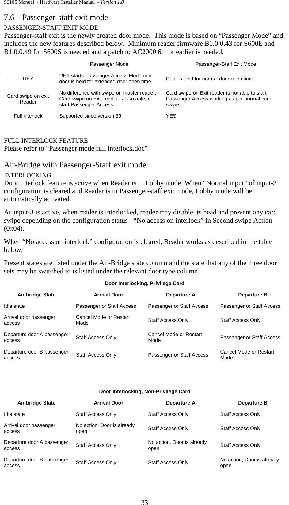
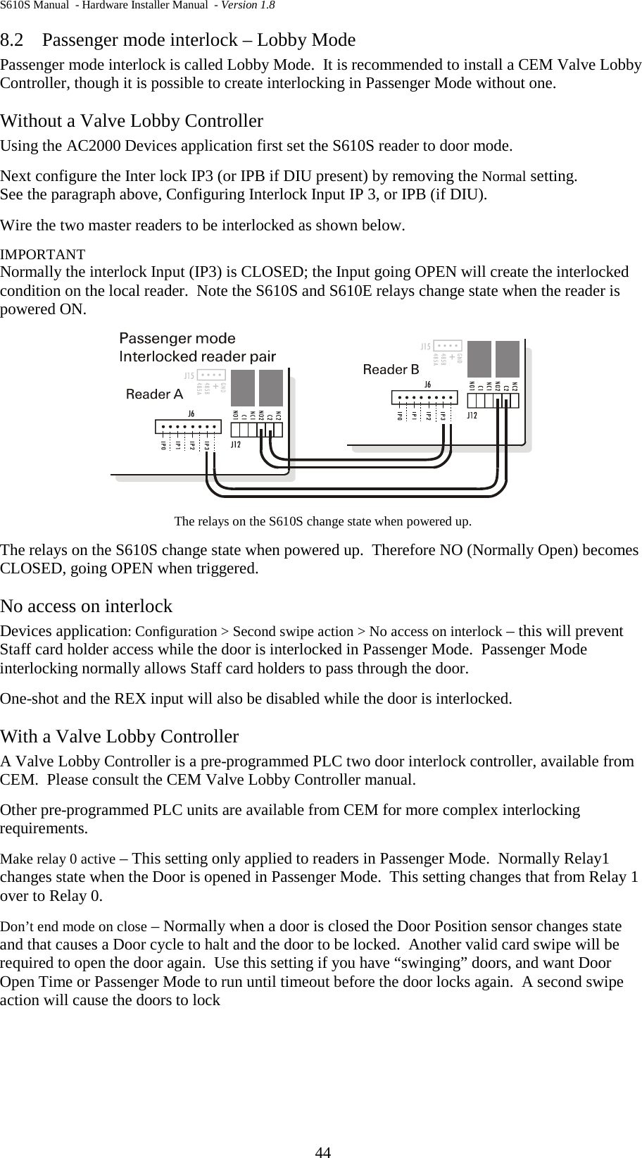
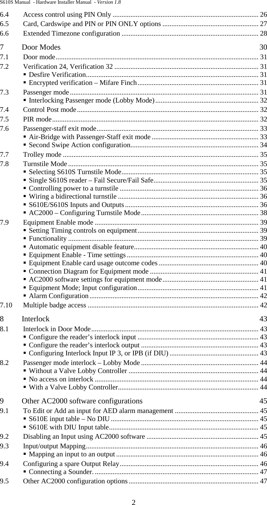
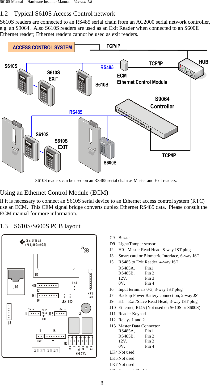
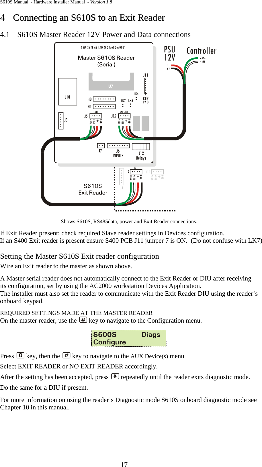
![S610S Manual - Hardware Installer Manual - Version 1.8 34 IDLE STATE In the idle state all doors are closed and locked and the Air-Bridge lobby is secured. The Air-Bridge lobby may change to either passenger access or staff access from the idle state. STAFF ACCESS Staff Access feature is designed to allow single person access. When reader is in the idle state, the normal card swipe de-energises electro-magnetic door lock for door open time while the special usage card swipe de-energises door lock for extended door open time. These door open times are configurable. PASSENGER ACCESS When a special usage card is swiped during Passenger Access mode active, the option to either Cancel or Restart the Passenger Access mode will be given. Cancelling the mode will energise electro-magnetic door lock and make reader ready to generate the door open alarm displaying “CLOSE DOOR !!” message on LCD. If door is not closed for a configured time, Reader will generate the door open alarm. Restarting the mode will re-initialise and extend the mode for the extended door open time. REX Using a REX which interrupts the Passenger Access mode will cancel the mode. When Reader is in the idle state and Door mode is Standard Passenger Mode, REX will start the Passenger Access mode de-energising door lock for the extended door open time. When Reader is in the idle state and Door mode is Passenger-staff exit Mode, REX will work as per a normal card swipe (door open time). Second Swipe Action configuration Second Swipe Action contains three special options to define the action of the card swipe during the Passenger Access mode is ON. Note that Second Swipe Action is basically designed for a special usage card swipe. In some cases, however, a normal card swipe will get the same effect. RE-ENABLE MODE Re-enable mode = 0x00 This is the default value of Second swipe action configuration. Special usage card swipe: When a special usage card is swiped during the Passenger Access mode, The reader displays Mode Extension Menu [ End * Restart # ] and this will allow card holder to either Cancel or Restart the mode. The second card swipe doesn’t affect the Passenger Access mode until one of options is selected and the mode is still on process counting down timer even though Mode Extension Menu is being displayed on the LCD. The diagram below shows a process sequence when Restart is selected. First Card swipe Second card swipe Restart Selected Door Close Mode Passenger Access Mode New Passenger Access Mode Door open time Door open time](https://usermanual.wiki/Controlled-Electronic-Management-Systems/S610MSCRM/User-Guide-2383622-Page-37.png)