Controlled Entry Distributors SK1-H Access Control User Manual
Controlled Entry Distributors, Inc. Access Control Users Manual
Manual
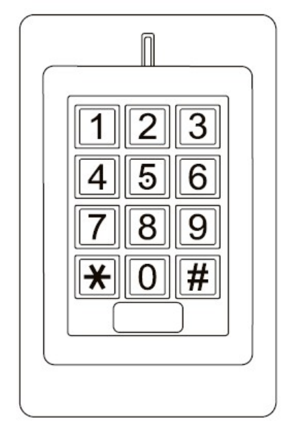
SK1-H
Waterproof Access Control/Reader
User Manual

2
INTRODUCTION
The SK1-H is a single- entry multi-function Access Controller with integrated keypad and card reader. It is
designed and manufactured to perform in a wide range of indoor, outdoor, and harsh environments.
The SK1 supports up to 1000 users in multiple access configurations (Card, Card or PIN, or Card + PIN). The
built in card reader supports HID 125KHz frequency cards. The relay can operate in Pulse Mode (suitable for
access control) or Toggle Mode (suitable for arming/disarming alarms, switching lights, machines….etc)
The SK1-H offers advanced programming features like: Duress PIN/card; Block enrollment; Wiegand 26~37
bits interface. These features make it an ideal choice for door access not only for small shops and domestic
households but also for commercial and industrial applications such as factories, warehouses, laboratories,
banks and prisons.
Features
Waterproof, meets IP66
Vandal Resistant Metal Enclosure
One Programmable Relay Output
Stand Alone or Pass-Through Operation
1000 Users (Card/ Card or PIN /Card+PIN)
10 Panic Card/PIN Codes
Latch Mode to hold door or gate open
Wiegand 26~37 bits input & output
Card Block enrollment
Integrated Alarm Buzzer & Output
Low power consumption (55mA)
Anti-Tamper Alarm
Backlit Keypad
Multi-color LED status display
12-24V DC/ 12-18V AC Power input
Specifications:
User Capacity
Normal User
Panic User
1010 Cards/PINS
1000
10
Operating Voltage
Idle Current
Active Current
12~24V DC/ 12-18V AC
55mA
80mA
Keypad
PIN length
12 Key (3*4)
4-6 digits
Proximity Card Reader
Radio Technology
Read Range
HID
125KHz Industry Standard Proximity Card
3- 6cm
Wiring Connections Electric Lock, Exit Button,
DOTL, External Alarm, Wiegand (in/out)
Relay
Adjustable Relay Output Time
ONE
(NO, NC, COM)
1-99 Seconds (5 seconds default)
3
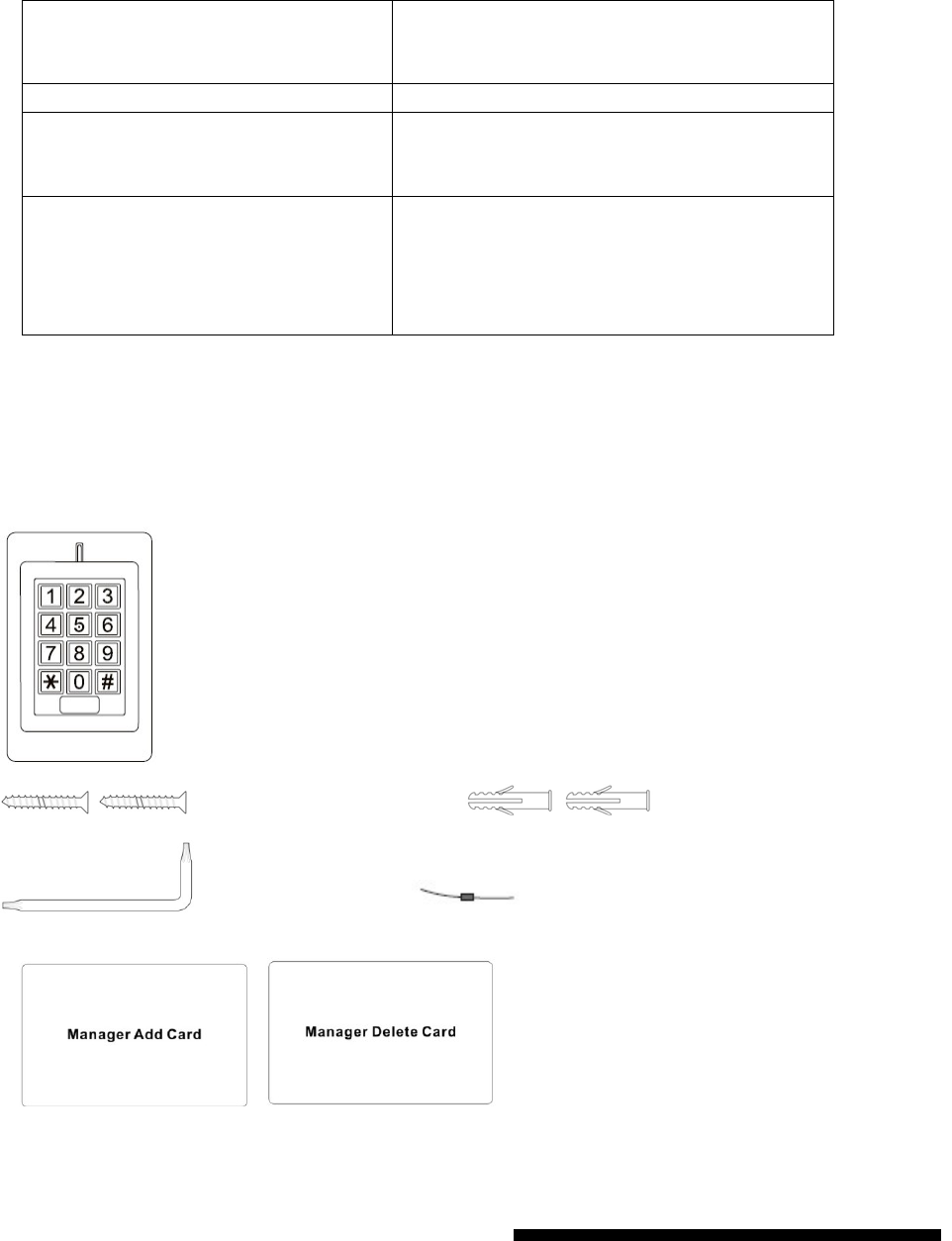
Carton Inventory
SK1-H Access Controller
Self Tapping Screws Wall Anchors
Screw Driver Diode IN4004 (For relay circuit protection)
Manager Card
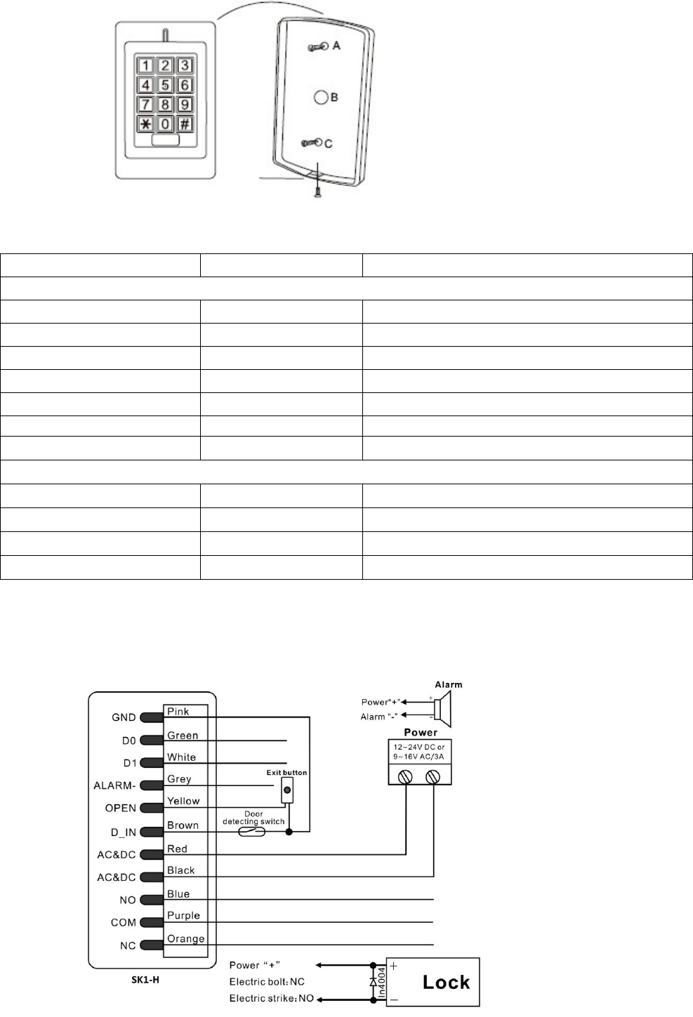
INSTALLATION
Install
Remove the back cover from the unit
Drill 2 holes(A,C) on the wall for the screws and one hole for the cable
Knock the supplied rubber bungs to the screw holes(A,C)
Fix the back cover firmly on the wall with 4 flat head screws
Thread the cable through the cable hole(B)
Adjustable Alarm Output Time
Lock Output Load
Alarm Output Load
0-3 minutes (1 minute default)
3 Amp Maximum
3 Amp Maximum
Wiegand Interface Wiegand 26-37 bit input/output
Environment
Operating Temperature
Operating Humidity
Meets IP66
-30℃ ~60℃, or -22°F ~ 140°F
10% ~ 90% Non-Condensing
Physical
Surface Finish
Dimensions
Unit Weight
Shipping Weight
Zinc-Alloy Enclosure
Powder Coat
L: 120* W: 76 * H: 25 (mm)
600g
700g
4
Attach the unit to the back cover.
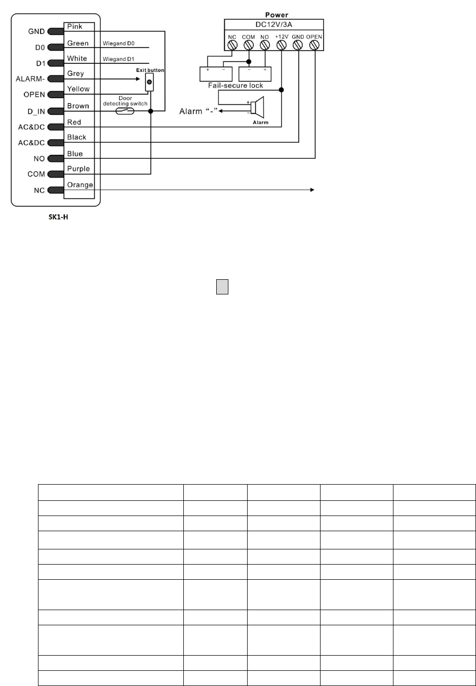
Wiring
Wire Color Function
Notes
Basic Standalone Wiring
Red AC&DC 12~24V DC/ 12-18V AC Regulated Power Input
Black AC&DC 12~24V DC/ 12-18V AC Regulated Power Input
Pink GND Negative Pole
Blue NO Normally Open Relay output
Purple COM Common Connection for Relay output
Orange NC Normally closed Relay Output
Yellow OPEN Request to Exit Button
Advanced Input and Output Features
Green D0 Wiegand Input/Output Data 0
White D1 Wiegand Input/Output Data 1
Grey Alarm - Alarm Negative
Brown D_IN Door status detecting
Connection Diagram
Common Power Supply
5
Access Control Power Supply
To Reset to Factory Default
To reset to factory default, power off, press * , hold it and power on, release it until hear two beeps and
the LED shines in orange, then read any two HID cards, the LED will turn in red, means reset to factory
default setting successfully. Of the two HID cards read, the first one is Manager Add Card, the second one
is Manager Delete Card.
Remarks: Reset to factory default, the user’s information is still retained.
Anti Tamper Alarm
The SK1-H uses a LDR (light dependent resistor) as an anti tamper alarm. If the keypad is removed
from the cover then the tamper alarm will operate.
Sound and Light Indication
Operation Status Red Light
Green Light
Yellow Light Buzzer
Power on Bright
-
-
Short Ring
Stand by Bright
-
-
-
Press keypad -
-
-
Short Ring
Operation successful -
Bright
-
Short Ring
Operation failed -
-
-
3 Short Rings
Enter into programming
mode
Bright
-
-
Short Ring
In the programming mode -
-
Bright
-
Exit from the
programming mode
Bright
-
-
Short Ring
Open the door -
Bright
-
Short Ring
Alarm Bright
-
-
Alarm
6
Standalone Operation
1.1 User Settings
To enter the programming mode * Master code #
666666 is the default factory master code
To exit from the programming mode *
Note that to undertake the following programming the master user must be logged in
To change the master code 0 New code # New code #
The master code is any 6 digits
Setting the working mode:
Set valid card or PIN users
Set valid card and PIN users
Set valid card only users
3 0 # Entry by either card or PIN (default)
3 1 # Entry by card and PIN together
3 2 # Entry by card only
To set a user in either card or PIN mode ( 3 0 # ) (Default setting)
To add a PIN user 1 User ID number # PIN #
The ID number is any number between 1~1000. The PIN is
any 4~6 digits between 0000~999999 with the exception
of 1234 which is reserved. Users can be added continuously
without exiting from programming mode as follows:
1 User ID no 1 # PIN # User ID no 2 # PIN #
To delete a PIN user 2 User ID number #
Users can be deleted continuously without exiting
programming mode
To change the PIN of a PIN user
(This step must be done out of programming
mode)
* ID number # Old PIN # New PIN #
New PIN #
To add a card user (Method 1)
This is the fastest way to add cards using ID
number auto generation.
1 Read card #
Cards can be added continuously without exiting
programming mode
To add a card user (Method 2)
This is the alternative way to add cards using
User ID Allocation. In this method a User ID
is allocated to a card. Only one user ID can be
allocated to a single card.
1 ID number # Card #
To add card user (Method 3)
Add a series cards users – Block Enrollment
5 ID number # The 1st Card number #
Card quantity #
Note that cards must be consecutive, and card quantity is
between 1~1000.
7
Maximum 1,000 cards can be enrolled at a stretch within 1
minute.
To delete a card user by card
Note users can be deleted continuously
without exiting programming mode
2 Read Card #
To delete a card user by user ID
This option can be used when a user has lost
their card
2 User ID #
To delete a card user by Card number
Users can be deleted continuously without
exiting from programming mode
2 Card number #
To set a card and PIN user in card and PIN mode ( 3 1 # )
To Add a card and PIN user
(The PIN is any 4~6 digits between
0000&999999 with the exception of 1234
which is reserved.)
Add the card as for a card user
Press * to exit from the programming mode
Then allocate the card a PIN as follows:
* Read card 1234 # PIN # PIN #
To change a PIN in card and PIN mode
(Method 1)
Note that this is done outside programming
mode so the user can undertake this
themselves
* Read Card Old PIN # New PIN #
New PIN #
To change a PIN in card and PIN mode
(Method 2)
Note that this is done outside programming
mode so the user can undertake this
themselves
* ID number # Old PIN # New PIN #
New PIN #
To delete a Card and PIN user just delete
the card
2 User ID #
To set a card user in card mode ( 3 2 # )
To add and delete a card user The operating is the same as adding and deleting a card
user in 3 0 #
To delete All users
To delete All users
Note that this is a dangerous option so use
with care
2 0000 #
To unlock the door
For a PIN user Enter the PIN then press #
8
For a card User Read card
For a card and PIN user Read card then enter PIN #
1.2 Master Cards Using
Using Master Card to add and delete card users
Add a User Card 1. (Read Master Add Card)
2. (Read User Card)
Repeat Step 2 for additional user cards
3. (Read Master Add Card)
Delete a User Card 1. (Read Master Delete Card)
2. (Read User Card)
Repeat Step 2 for additional user cards
3. (Read Master Delete Card)
1.3 Relay Setting (Pulse mode, Toggle mode)
Pulse mode
(
factory default
)
Pulse mode - door relay time setting 4 1~99 #
The door relay time is between 1~99 seconds, the
factory default setting is 5 seconds.
Toggle mode (Latch mode)
Toggle mode 4 0 #
1.4 Door Detecting, Alarm, Sound and Light Settings
Door Open Detection
Door Open Too Long (DOTL) warning
. When used with an optional magnetic contact or built-in
magnetic contact of the lock, if the door is opened normally, but not closed after 1 minute, the
inside buzzer will beep automatically to remind people to close the door and continue for 1 minute
before switching off automatically.
Door Forced Open warning.
When used with an optional magnetic contact or built-in magnetic
contact of the lock, if the door is opened by force, or if the door is opened after 20 seconds of
the electro-mechanical lock not closed properly, the inside buzzer and alarm output will both
operate. The Alarm Output time is adjustable between 0~3 minutes with the default being 1
minute.
To disable door open detection
(Factory default)
6 0 #
To enable door open detection 6 1 #
Keypad Lockout & Alarm Output options.
If there are 10 invalid cards or 10 incorrect PIN
numbers in a 10 minute period either the keypad will lockout for 10 minutes or the alarm will
operate for 10 minutes, depending on the option selected below.
Normal status: No keypad
7 0 # (factory default)
9
lockout or alarm (factory
default)
Keypad Lockout 7 1 #
Alarm Output 7 2 #
Light and Sound Setting
To set keypad backlight 7 4 # To disable keypad backlight
7 5 # To enable the keypad backlight (factory default)
To set LED 7 6 # To disable the red LED
7 7 # To enable the red LED (factory default)
To set keypad tone 7 8 # To disable the keypad tone
7 9 # To enable the keypad tone (factory default)
Alarm output time
To set the alarm output time (0~3
minutes)
Factory default is 1 minute
9 0~3 #
To remove the alarm
To reset the Door Forced Open
warning
Read valid card or Master Code #
To reset the Door Open Too Long
warning
Close the door or Read valid card or Master Code #
1.5. Panic User Setting
There are 10 groups Panic PIN/card available. When people are under duress to open the
door, they can use the panic PIN or card, and under the situation, the door will open, at
the same time, the output alarm operates.
To set Panic PIN User
To add a PIN user 8 user ID number # PIN #
(The ID number is any number between 1001~1010.)
To delete a PIN user 2 user ID number #
To set Panic card user
To add a card user 8 user ID number # card #
(The ID number is any number between 1001~1010.)
To delete a card user 2 user ID number #
Note:
① User ID number must be any 4digits between 1001~1010
② Panic PIN/card must be unique, should be distinguished from common PIN and card
(When the Panic PIN/card is the same with common PIN and card, they will become
invalid in Duress, and worked as common user function)
10
Wiegand Mode
Wiegand Format Setting
SK1-H supports Wiegand 26~37, both input and output. It can be used as a reader or
controller.
To Set Wiegand format: 9 26~37 # (Default setting: Wiegand 26)
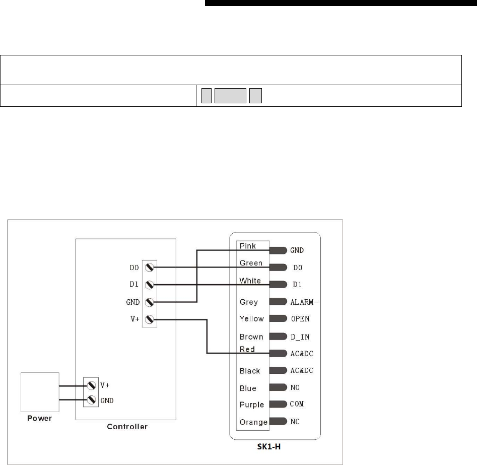
Pass through mode (SK1-H operating as a Wiegand Output Reader)
In this mode the SK1-H supports a Wiegand 26~37 bit output so the Wiegand data lines can be connected to
any controller which supports a Wiegand 26~37 bit input, then the SK1-H will be operated as a slave reader.
Wiring Diagram
Transmission Format:
Keypad Transmission
The Reader will transmit the PIN data when it receives the last key (#) press after PIN code.
Format: PIN Code (any 4~6 digits between 0000~999999)
Example: PIN code: 123456
Press 123456 #, then the output format will be: 0000123456
(Note: if press an invalid PIN (any 4~6 digits), the data will be also transmitted.)
Proximity Card Transmission
The Reader will transmit the card data when it reads the Card.
Format: Card Number
(Note: no matter the card is valid or invalid, the data will be transmitted)
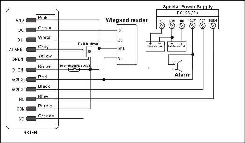
Controller Mode (SK1-H operating as a Controller)
SK1-H supports a Wiegand 26~37 bit input so an external Wiegand device with a 26~37 bit output can be
11
connected to the Wiegand input terminals on the SK1-H. Either an ID card reader (125 KHz) or an IC card
reader (13.56MHz) can be connected to the SK1-H. Cards are required to be added at the external reader,
except where an external HID reader is used, in this case cards can be added at either reader or controller.
Wiring Diagram

12
SK1-H- Simplified Instruction
Function Description Operation
Enter the Programming Mode * (Master Code) #
(666666 is the default factory master code)
Change the Master Code 0(New Master Code )
#
(Repeat New Master
Code)#
(code: 6 digits)
Add Card User 1 (Read Card) #
Add PIN User 1 (User ID) # (PIN) #
The ID number is any number between 1 ~ 1000. The
PIN is any 4-6 digits between 0000 ~ 999999
Delete User 2 (Read Card)
#
2 (User ID) #
Exit from the programming mode *
How to be granted access.
Card User Read card
PIN User Enter (PIN) #
FCC STATEMENT:
This device complies with Part 15 of the FCC Rules. Operation is subject to the following two conditions:
This device may not cause harmful interference, and
This device must accept any interference received, including interference that may cause undesired
operation.
Warning: Changes or modifications not expressly approved by the party responsible for compliance could
void the user's authority to operate the equipment.
NOTE: This equipment has been tested and found to comply with the limits for a Class B digital device,
pursuant to Part 15 of the FCC Rules. These limits are designed to provide reasonable protection against
harmful interference in a residential installation.
This equipment generates uses and can radiate radio frequency energy and, if not installed and used in
accordance with the instructions, may cause harmful interference to radio communications. However, there
is no guarantee that interference will not occur in a particular installation. If this equipment does cause
harmful interference to radio or television reception, which can be determined by turning the equipment off
and on, the user is encouraged to try to correct the interference by one or more of the following measures:
Reorient or relocate the receiving antenna.
Increase the separation between the equipment and receiver.
Connect the equipment into an outlet on a circuit different from that to which the receiver is connected.
Consult the dealer or an experienced radio/TV technician for help.