Controlled Entry Distributors TCO900 Entry control system User Manual 1620135 ENG TCOO900 RCOO900 rev 1
Controlled Entry Distributors, Inc. Entry control system 1620135 ENG TCOO900 RCOO900 rev 1
User Manual
TCOO900 - RCOO900
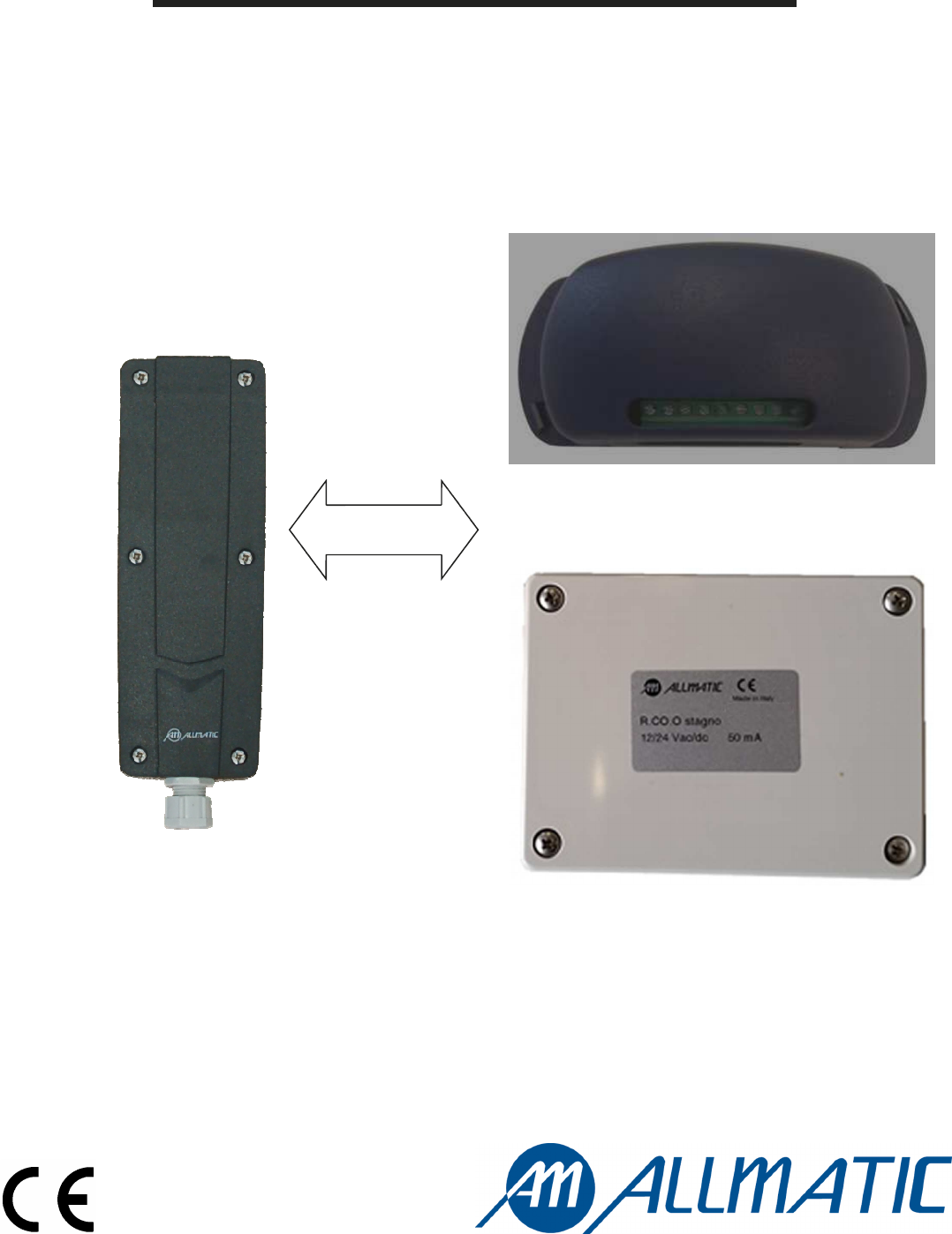
TCOO900
RCOO900 in box
Bidirectional
communication
RCOO900 in watertight box
Transceiver system for mechanical safety and
8,2kΩ resistive edges
ITA ENG FRA ESP DEU POR
2 / 8
6-1620135 rev.1 08/07/2015
SAFETY 1 Mechanical safety edge (N.C./N.O.) Resistive safety edge 8,2kΩ Mechanical safety edge (N.C./N.O.)
SAFETY 2 Mechanical safety edge (N.C./N.O.) Mechanical safety edge (N.C./N.O.) Resistive safety edge 8,2kΩ
Resistive safety edge 8,2kΩ
Mechanical safety edge (N.C./N.O.)
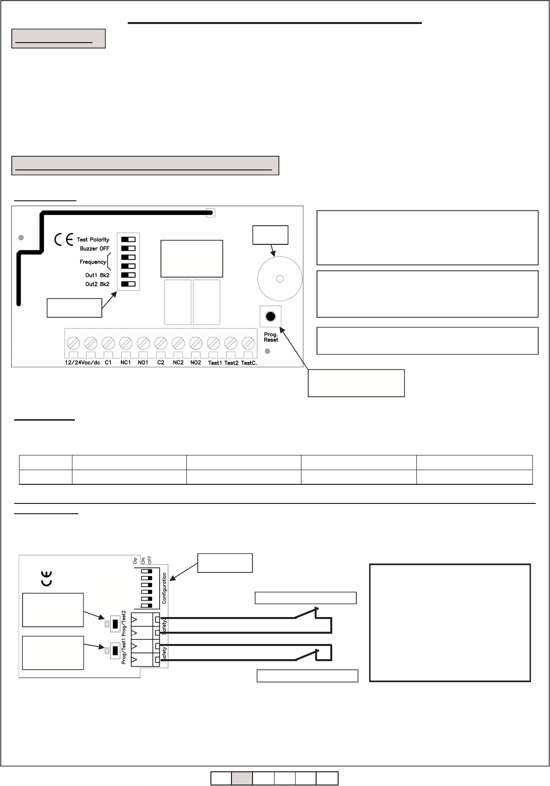
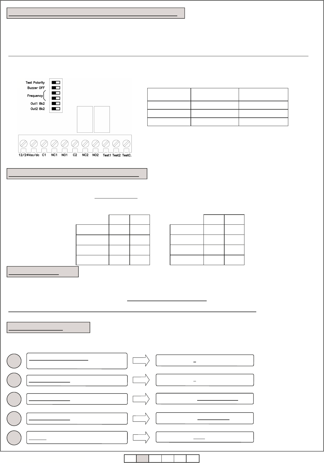
2. CONFIGURATION AND ELECTRICAL CONNECTIONS
1. DESCRIPTION
The system is intended as safety device for gates and includes a RCOO900 (connected to the control unit) and maximum 8 TCOO900 (maximum 8
safety edge for each relay). It can work with both mechanical edges (dry contact N.C. or N.O), and 8,2kΩ resistive edges. The contacts of the fixed
device are independent and can be connected to the relative input of the control unit, put in series to the stop of the control unit, or in series to the
photo devices contacts. Two contacts are also present on the fixed device to be able to carry out the self – test system.
The transmission of the signals between fixed and movable device happens on 902-928 MHz band in bidirectional way.
The installation and the maintenance of the system must be carried out by qualified personnel. Allmatic can not be considered responsible
for any damages caused by an improper, incorrect or irrational use of the product.
Warning: this device can block the automation if the batteries of the movable part is flat.
NOTE: The signals given on the outputs to the relay 1 and 2
are a N.C. contact and a N.O. contact or a N.C. contact and a
resistive output (8,2kΩ). It depends on the setting of dip
switch 5 and 6.
2.2 TCOO900
2.1 RCOO900
Transceiver system for safety edge
Dip switch
Programming / reset key
WARNING: if the power supply of the RCOO900 is carried
out in alternating current (Vac), the power supply must be got
through an insulation transformer (of security, SELV tensions)
which has a limited power or almost a protection against the
short circuit.
Output relay
0.5A a 42.4Vac
1A a 30Vdc
WARNING:
DIP1 OFF: mechanical safety edge 1
If you want to connect a mechanical element on
the input Safety1 (normally closed contact), you
must set dipswitch 1 on «OFF».
DIP2 OFF: mechanical safety edge 2
If you want to connect a mechanical element on
the input Safety2 (normally closed contact), you
must set dipswitch 2 on «OFF».
DIP6 OFF: mechanical safety edge N.C.
If you want to use a mechanical safety edge with a
normally closed contact , you must set dip
switch 6 on «OFF».
NOTE: The level of acoustic pressure generated by the
device is less then 70 dBA.
Led and
programming /
test key 2
Dip switch
Led and
programming /
test key 1
Mechanical edge 1 (N.C.)
Each TCOO900 can be connected to a single RCOO900.
It is possible to connect to the TCOO900 a single safety edge or two different safety edges in the same moment (inputs Safety1 and Safety2). Possible
configurations are:
Mechanical edge 2 (N.C.)
Example: TCOO900 + Mechanical safety edge N.C. 1 + Mechanical safety edge N.C. 2
F
Frequency
Low Power
Safety2 Type
Safety1 Type
Safety2
Safety1
Buzzer
OFF ON
WARNING: in case of use of mechanical safety edges, both safety edges must have a normally open contact or a normally
closed contact.
8k2
8k2
1 2 3 4 5 6
1 2 3 4
5 6
ITA ENG FRA ESP DEU POR
3 / 8
6-1620135 rev.1 08/07/2015
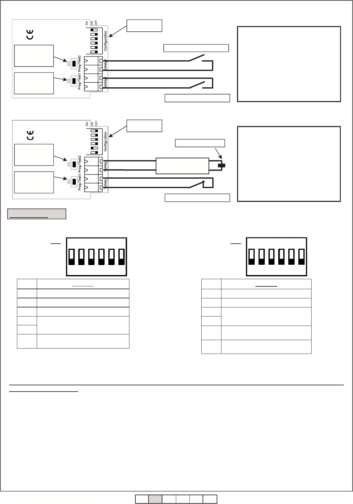
N° DIP Funzione
1 Mechanical (OFF) or resistive (ON) edge 1.
2 Mechanical (OFF) or resistive (ON) edge 2.
3 Low Power.
4
5
6 Mechanical edge with N.C. contact (OFF) or
Mechanical edge with N.O. contact (ON)
Selection frequency of functioning.
It is possible to associate up to a maximum of 8 T.CO.O900 to each RCOO900, while it is possible to associate up to a maximum of 8 different edges
to each relay.
WARNING: for a correct functioning of the system, every TCOO900 must have the frequency dip put on the same way as the
correspondent RCOO900.
On safety system with more than one RCOO900, to avoid interference, we recommend to set different frequency on different RCOO900 and the
associated TCOO900.
RCOO900
3. SETTINGS
TCOO900
DIP
ON
OFF 1 2 3 4 5 6
N° DIP Funzione
1 Test device.
2 Buzzer ON / OFF.
3
4
5 NO1 output: N.O. contact (OFF) or 8k2
signal (ON) 1.
6 NO1 output: N.O. contact (OFF) or 8k2
signal (ON) 2.
Selection frequency of functioning.
DIP
ON
OFF 1 2 3 4 5 6
ATTENZIONE:
DIP1 OFF: mechanical safety edge 1
If you want to connect a mechanical element on
the input Safety1 (normally closed contact), you
must set dipswitch 1 on «OFF».
DIP2 ON: resistive safety edge 8,2kΩ 2
If you want to connect a resistive element on the
input Safety2 (8k2 resistor), you must
set dipswitch 2 on «ON».
DIP6 OFF: mechanical safety edge N.C.
If you want to use a mechanical safety edge with
a normally closed contact , you must set dip
switch 6 on «OFF».
Dip switch
Resistive edge 2
Resistance 8,2kΩ
Example: TCOO900 + 8,2kΩ resistive edge 1 + Mechanical safety edge N.C. 2
Led and
programming /
test key 2
Led and
programming /
test key 1
F
Frequency
Low Power
Safety2 Type
Safety1 Type
Safety2
Safety1
Mechanical edge 1 (N.C.)
Led and
programming /
test key 2
Dip switch
Led and
programming /
test key 1
Mechanical edge 1 (N.O.)
Mechanical edge 2 (N.O.)
Example: TCOO900 + Mechanical safety edge N.O. 1 + Mechanical safety edge N.O. 2
F
Frequency
Low Power
Safety2 Type
Safety1 Type
Safety2
Safety1
1 2 3 4 5 6
1 2 3 4 5 6
WARNING:
DIP1 OFF: mechanical safety edge 1
If you want to connect a mechanical element on
the input Safety1 (normally closed contact), you
must set dipswitch 1 on «OFF».
DIP2 OFF: mechanical safety edge 2
If you want to connect a mechanical element on
the input Safety2 (normally closed contact), you
must set dipswitch 2 on «OFF».
DIP6 ON: mechanical safety edge N.O.
If you want to use a mechanical safety edge with a
normally open contact , you must set dip
switch 6 on «ON».
ITA ENG FRA ESP DEU POR
4 / 8
6-1620135 rev.1 08/07/2015
Depending on the type of signal required, connect the outputs as
explained in the following table:
OUTPUT SIGNAL USED TERMINAL
BOARD SETTING OF
DIP SWITCH
N.C. contact NC1-C1 (o NC2-C2) -
N.O. contact NO1-C1 (o NO2-C2) DIP5 OFF (o DIP6 OFF)
8,2kΩ resistive NO1-C1 (o NO2-C2) DIP5 ON (o DIP6 ON)
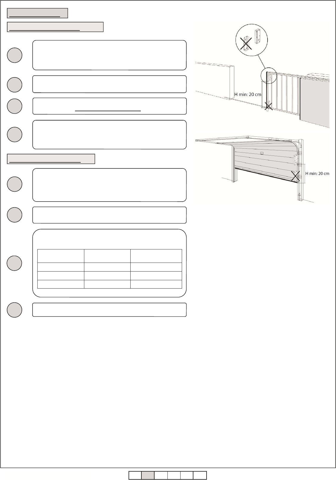
3
4
Fix the device as much higher than possible in such way as there are
no obstacles on the direction of the receiver and in such a way as the
maximum distance between the two devices is less than 15 meters
(max 20 meters).
2
Set the dip switch relative to the utilized frequency (DIP 4 and DIP 5)
which will have to correspond to the one of the RCOO900.
4. CONNECTIONS
4.1 TCOO900 connection
1
Connect the sensitive edge to the terminal boards of the device. Set
the dip switch relative to the type of the used safety edge (DIP 1, DIP
2 and DIP 6).
Orientate and put the device as explained in figure.
Give power to the system connecting the two batteries AA – 1,5 V to
the battery holder. Pay attention to the polarity .
2
3
4
Connect the test inputs to the control unit, in case they are utilized (*).
1
4.2 RCOO900 connection
Put the RCOO900 in such a way to minimize the distance from the
associated TCOO900 and close the to the automation’s control unit
or inside the box of the motor. If fixed to a wall, utilize suitable screws
and plugs so that it can resist to a force of 50N downwards.
Set the dip switch relative to the utilized frequency (DIP 3 and DIP 4)
which will have to correspond to the one of the TCOO900.
(*) The inputs are handled in the same way as the photocells test: the control unit, to carry out the photocells test, switches off the power supply of the
receiver and check that the relays of the correspondent receiver opens itself. In this device, the input TEST1 and TEST2 are for testing the security
devices (see paragraph 12).
WARNING : Allmatic can not be considered responsible
for any damages caused by an improper, incorrect or
irrational use of the product.
WARNING: keep free the areas of access to the devices
and clean periodically them from eventual dirtiness
which can settle on them during the normal
functioning.
WARNING: install the TCOO900 at minimum height of
20 cm from the ground.
ITA ENG FRA ESP DEU POR
5 / 8
6-1620135 rev.1 08/07/2015
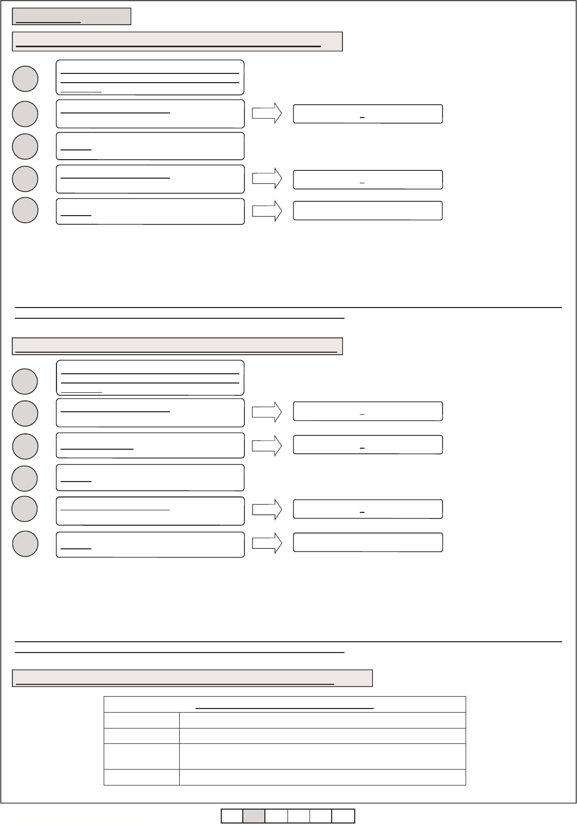
5.2 Learning of the TCOO900 on the second relay of the RCOO900
3
4
6
Release the key on the TCOO900.
RCOO900 emits 2 BIP. (*)
The learning ended correctly.
1
Check that the DIP 4 and 5 of the TCOO900
and DIP 3 e 4 of the RCOO900 are set in the
same way.
Press and keep pressed the key on the
TCOO900 relative to the used input.
5
Number of BIP Meaning
2 Transmitter correctly memorized
4 Fault: the maximum number of safety edges for selected channel has been
reached
1 Maximum time expired for the memorization of the transmitter (10 second)
Acoustic signalling during the learning phase
5.3 Summary of the acoustic signalling during the learning phase
2
2
RCOO900 emits 1 BIP.
3
4
Press and keep pressed the key on the
RCOO900.
Release the key on the RCOO900.
RCOO900 emits 2 BIP. (*)
1
5. LEARNING
5.1 Learning of the TCOO900 on the first relay of the RCOO900
Check that the DIP 4 and 5 of the TCOO900
and DIP 3 e 4 of the RCOO900 are set in the
same way.
Press and keep pressed the key on the
TCOO900 relative to the used input.
Release the key on the TCOO900.
5
The learning ended correctly.
For the successive learning, repeat the operation from point 1.
Press and keep pressed the key on the
RCOO900.
DO NOT RELEASE the key on the RCOO900.
Release the key on the RCOO900.
RCOO900 emits 1 BIP.
RCOO900 emits 2 BIP.
NOTE: when the TCOO900 is used with two connected safety edges, it is necessary to carry out the learning two times, one for each input.
WARNING: the same input of the TCOO900 can be memorized on both the relay. To erase the memorized input it is
necessary to carry out a complete reset of the RCOO900 (see paragraph 9).
(*) In case in which 4 BIP are reproduced, it means that the maximum number of safety edges for the selected channel has been reached and that no
new devices on the same relay can be memorized.
For the successive learning, repeat the operation from point 1.
NOTE: when the TCOO900 is used with two connected safety edges, it is necessary to carry out the learning two times, one for each input.
WARNING: the same input of the TCOO900 can be memorized on both the relay. To erase the memorized input it is
necessary to carry out a complete reset of the RCOO900 (see paragraph 9).
(*) In case in which 4 BIP are reproduced, it means that the maximum number of safety edges for the selected channel has been reached and that no
new devices on the same relay can be memorized.
ITA ENG FRA ESP DEU POR
6 / 8
6-1620135 rev.1 08/07/2015
Through to the button on the RCOO900 it is possible, further than to carry out the programming of the TCOO900 (see paragraph 5), to carry out the
reset of the device deleting all the associated TCOO900. Proceed as follows to carry out the reset:
9. RCOO900 RESET
2
3
RCOO900 emits 1 BIP.
5
Release the key on the RCOO900.
Press and keep pressed the key on the
RCOO900.
DO NOT RELEASE the key on the RCOO900.
RCOO900 emits 6 BIP. The reset is ended.
1
RCOO900 emits 2 BIP.
4
DO NOT RELEASE the key on the RCOO900. RCOO900 emits a series of close BIP.
DO NOT RELEASE the key on the RCOO900. RCOO900 emits a continuos BIP.
The battery life is of about 2 years (5 years in Low Power modality). The TCOO900 keeps constantly under control the state of its batteries. When the
tension gets down under a pre – set value, this state is signaled to the associated RCOO900 which signals it (if the buzzer is active) with 4 BIP. If the
battery is not substituted, the TCOO900 will continue to regularly work until the tension of the batteries won’t get down under the minimum safety
threshold. If this happens, the RCOO900 will signal it with 5 BIP putting itself in state of alarm .
The device will remain in state of alarm until the battery of the transmitter won’t be substituted.
The substitution of the battery must be carried out by qualified personnel being necessary to open the TCOO900.
For each RCOO900 and relative TCOO900 it is possible to select a work frequency. This allows to be able to utilize up to a maximum of 4 RCOO900
on the same range of action without interferences.
For a correct functioning of the system it is indispensable that the frequency set on the RCOO900 corresponds to the frequency set on the
associated TCOO900. The selection of the frequency happens with DIP 3 and 4 on the RCOO900 and with DIP 4 and 5 on the TCOO900 as reported
on the following tables:
RCOO900 DIP 3 DIP 4
Frequency 1 ON ON
Frequency 2 ON OFF
Frequency 3 OFF ON
Frequency 4 OFF OFF
7. SELECTION OF THE WORKING FREQUENCY
8. FLAT BATTERY
TCOO900 DIP 4 DIP 5
Frequency 1 ON ON
Frequency 2 ON OFF
Frequency 3 OFF ON
Frequency 4 OFF OFF
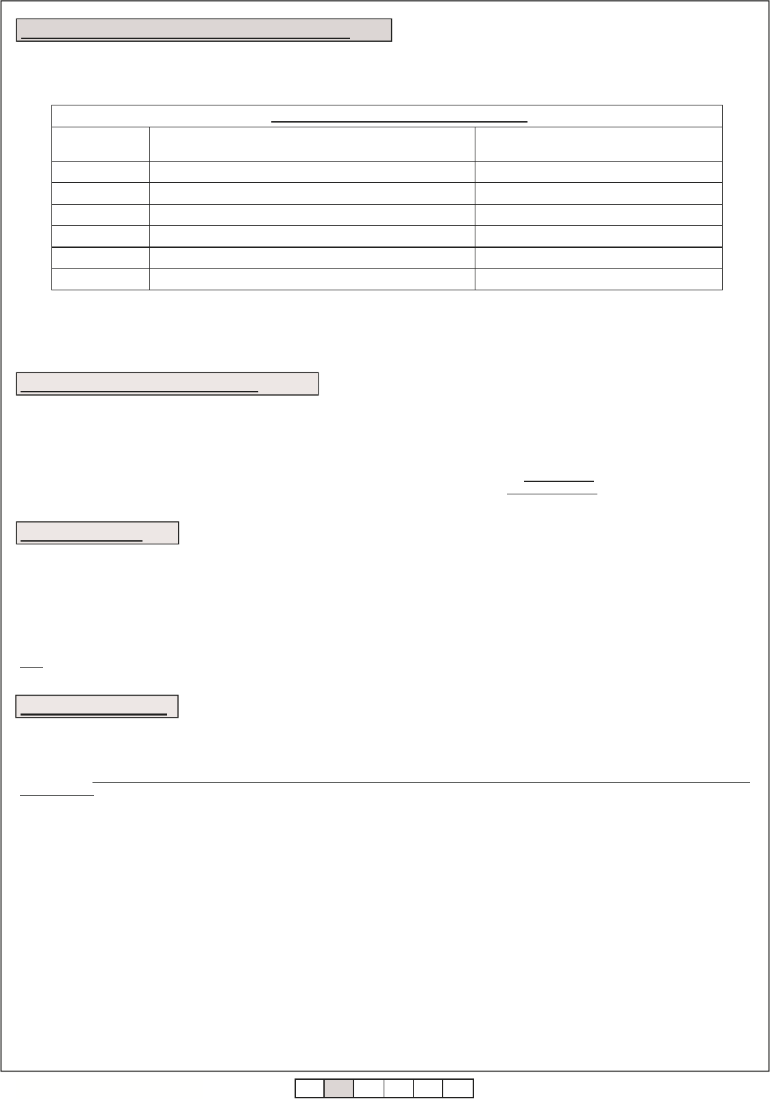
6. SELECTION OF THE TYPE OF SIGNAL ON OUTPUT RELAY
Each relay has two different outputs. These outputs are:
1. N.C. contact (contact opens in case of alarm and closes if there is not alarm);
2. N.O. contact (contact closes in case of alarm and opens if there is not alarm) or a contact type 8K2 (resistance of the contact = 0Ω in case of
alarm and resistance of the contact = 8,2kΩ if there is not alarm): the selection of the output type is through dip switches 5 and 6.
WARNING: in case of using 8k2 signal, the control unit connected to the device must be able to handle this type of signal.
The selection of the signal type is carried out in the following way:
OUTPUT SIGNAL USED TERMINAL
BOARD SETTING OF
DIP SWITCH
N.C. contact NC1-C1 (o NC2-C2) -
N.O. contact NO1-C1 (o NO2-C2) DIP5 OFF (o DIP6 OFF)
8,2kΩ resistive NO1-C1 (o NO2-C2) DIP5 ON (o DIP6 ON)
8k2
8k2
1 2
3 4 5
6
ITA ENG FRA ESP DEU POR
7 / 8
6-1620135 rev.1 08/07/2015
Through the dip switch Low Power present on the TCOO900 it is possible to limit the frequency with which it transmits its state of functioning (period of
interrogation): in this case it will be necessary to keep in consideration the dangerous condition that can be created if the power supply (battery) is
taken off from the TCOO900 during the interval of time before the successive transmission of its state and successively to the alarm from the safety
edge: in this case the RCOO900 will signal the alarm only after the period of interrogation.
With the dip 3 of the TCOO900 on OFF: energy saving deactivated, it checks the state of the TCOO900 each second (Low Power deactivated)
With the dip 3 of the TCOO900 on ON: energy saving activated, it checks the state of the TCOO900 each 15 seconds (Low Power activated)
11. ENERGY SAVING (LOW POWER)
12. DEVICES TEST
Through the dip switch 1 of the RCOO900 it is possible to select if the device test must be carried out with a high logic signal (so the test will activate
itself if between the terminals TEST1 and TESTC will be present a tension from 10V dc to 24 Vdc) or with a low logic signal (so the test will activate
itself if between the terminals TEST1 and TESTC will be present a tension of 0Vdc). In this case, the test will be carried out for the device memorized
to the relay 1. The same is for TEST2 and TESTC for the device memorized to the relay 2.
With the dip 1 of the RCOO900 on OFF: the test of the device is executed by applying a high logic signal 10-24 Vdc at the input.
With the dip 1 of the RCOO900 on ON: the test of the device is executed by applying a low logic signal 0 Vdc at the input.
Note: in case you do not want to use the test of the device, place the dip 1 on OFF.
On each TCOO900, two keys, said “programming/test key”, and two leds are present. The pressure of the key of the safety edge that is tested during
the normal functioning (so not in programming) produces a signal that is sent to the receiver which close the contact of the relay and answers to this
signal with:
Number of BIP /
BLINK
Meaning
1 Regular functioning, no mistake found.
2 One or more sensitive edges on alarm.
3 One or more 8K2 sensitive edges disconnected.
Acoustic signaling during the normal functioning
4 Battery tension under the level of attention.
5 Battery tension under the minimum level.
6 One or more associated devices disconnected
What to do
-
Check the sensitive edges connected
Check the sensitive edges connected
Substitute the batteries of the indicted device
Substitute the batteries of the indicted device
Check each associated device
10. PROGRAMMING / TEST KEY OF THE TCOO900
Note: If one TCOO900 is in alarm but it necessary to open or close the automation in any case, it’s necessary to press and keep pressed the
programming / test button of the indicted TCOO900 and in the same time move the automation.
WARNING: If the batteries are completely flat, it will be necessary to change them.
13. FCC COMPLIANCE
This device complies with part 15 of the FCC rules. Operation is subject to the following two conditions: (1) This device may not cause harmful
interference, and (2) this device must accept any interference received, including interference that may cause undesired operation.
IMPORTANT! Any changes or modifications not expressly approved by the party responsible for compliance could void the user’s authority to operate
this equipment.
NOTE: This equipment has been tested and found to comply with the limits for a Class B digital device, pursuant to part 15 of the FCC Rules. These
limits are designed to provide reasonable protection against harmful interference in a residential installation. This equipment generates, uses and can
radiate radio frequency energy and, if not installed and used in accordance with the instructions, may cause harmful interference to radio
communications. However, there is no guarantee that interference will not occur in a particular installation. If this equipment does cause harmful
interference to radio or television reception, which can be determined by turning the equipment off and on, the user is encouraged to try to correct the
interference by one or more of the following measures:
•
Reorient or relocate the receiving antenna.
•
Increase the separation between the equipment and receiver.
•
Connect the equipment into an outlet on a circuit different from that to which the receiver is connected.
•
Consult the dealer or an experienced radio/ TV technician for help.
FCC Radiation Exposure Statement
This equipment complies with FCC radiation exposure limits set forth for an uncontrolled environment. This equipment should be installed and
operated with minimum distance 20cm between the radiator and your body.
ITA ENG FRA ESP DEU POR
8 / 8
6-1620135 rev.1 08/07/2015
Caratteristiche tecniche Technical features
Nome dispositivo mobile Movable device name TCOO900
Nome dispositivo fisso Fixed device name RCOO900
Frequenza Frequency 902-928 Mhz
Portata del sistema in campo libero Range of the system in free space 20 m
Alimentazione TCOO900 TCOO900 power supply 2 batterie / batteries AA
Alimentazione RCOO900 RCOO900 power supply 12/24 Vac-dc
Durata batteria Battery duration 2 anni (modalità funzionamento normale).
5 anni (modalità risparmio energetico).
2 years (normal functioning mode).
5 years (Low Power mode).
Coste di sicurezza compatibili Compatible safety edges
Meccaniche (N.C. o N.O.) e/o resistive
(8,2kΩ).
Mechanical (N.C. o N.O.) and/or resistive
(8.2 kΩ).
Numero di uscite Number of output 2
Numero massimo di TCOO900
associabili per ogni RCOO900 Maximum number of TCOO900 for
each RCOO900 8 per ogni dispositivo.
8 for each device.
Numero massimo di coste di
sicurezza associabili per ogni uscita Maximum number of safety edges for
each output 8 per ogni relè.
8 for each relay.
14. TECHNICAL FEATURES
GUARANTEE - In compliance with legislation, the manufacturer’s guarantee is valid from the date stamped on the product and is restricted to the re-
pair or free replacement of the parts accepted by the manufacturer as being defective due to poor quality materials or manufacturing defects. The
guarantee does not cover damage or defects caused by external agents, faulty maintenance, overloading, natural wear and tear, choice of incorrect
product, assembly errors, or any other cause not imputable to the manufacturer. Products that have been misused will not be guaranteed or repaired.
Printed specifications are only indicative. The manufacturer does not accept any responsibility for range reductions or malfunctions caused by environ-
mental interference. The manufacturer’s responsibility for damage caused to persons resulting from accidents of any nature caused by our defective
products, are only those responsibilities that come under Italian law.
ALLMATIC S.r.l
32020 Lentiai - Belluno – Italy
Via dell-Artigiano, n°1 – Z.A.
Tel. 0437 751175 – 751163 r.a. Fax 0437 751065
http://www.allmatic.com - E-mail: info@allmatic.com