Cooper Bussmann Ct02Man Users Manual B Line Cable Tray Based On The 2002 National Electrical Code®
CT02MAN CT02MAN
CT02MAN to the manual f719ec89-687d-4585-ac14-aef5a24ba954
2015-02-05
: Cooper-Bussmann Cooper-Bussmann-Ct02Man-Users-Manual-532048 cooper-bussmann-ct02man-users-manual-532048 cooper-bussmann pdf
Open the PDF directly: View PDF ![]() .
.
Page Count: 60
CABLE TRAY MANUAL
Based on the
2002 National Electrical Code®
2002
CT02MAN


Table of Contents Page
No.
Introduction ...................................................................................................................... 2
Why Cable Tray?
Safety .................................................................................................................... 3
Dependability ........................................................................................................... 4
Space Savings .......................................................................................................... 4
Cost Savings ......................................................................................................... 5-8
An In-depth Look at the 2002 NEC®, Section 392
Types of Cable Trays (NEC®392.1 Scope)............................................................ 9-11
EMI/RFI Cable Tray ......................................................................................... 10-11
Cable Tray Materials ............................................................................................... 12
Types of Cables Allowed in Cable Tray [392.3 (A)]..................................................... 12
MI - Mineral Insulated Metal Sheathed Cable [Article 332] ............................... 12
MC - Metal Clad Cable [Article 330] .............................................................. 13
TC - Power and Control Tray Cable [Article 336] ........................................... 13
ITC - Instrumentation Tray Cable [Article 727] ............................................... 13
PLTC - Power Limited Tray Cable [Sections 725.61 (C) and 725.71 (E)] .......... 14
Other Types - Fire Alarm [Article 760],
Multipurpose and Communications Cable [Article 800] ................14
Single Conductor & Type MV Cables [392.3 (B)]....................................................... 14
Cable Tray Use in Hazardous Locations [392.3 (D)].............................................. 15-17
Limitations on Cable Tray Use [392.4] ..................................................................... 18
Cable Tray Loading [392.5 (A)]........................................................................... 18-20
Fiberglass Cable Tray [392.3 (E) & 392.5 (F)]............................................................ 20
Discontinuous Cable Tray and Fittings [392.6 (A)] ................................................ 21-22
Covers [392.6 (D)]................................................................................................... 23
Barriers [392.6 (E) & (F)].......................................................................................... 24
Spacing of Multiple Cable Trays [392.6 (I)] ................................................................ 25
Supporting Conduit from Cable Tray [392.6 (J)] ........................................................ 25
Use of Cable Tray as an Equipment Grounding Conductor [392.7 Grounding]........ 26-29
Fastening Cables [392.8 (B)] .................................................................................... 30
Cable Installation [392.8] ................................................................................... 30-32
Sizing Cable Tray
Multiconductor - 2000 volts or less [392.9]............................................... 32-34
Single conductor - 2000 volts or less [392.10]........................................... 34-36
Type MC or MV - 2001 volts or greater [392.12] ........................................... 37
Ampacities of Cables in Cable Tray .................................................................... 36-38
Cable Tray Wiring System Design and Installation Hints ....................................... 38-39
Fireproofing Tray ................................................................................................... 40
Expansion and Contraction ............................................................................... 41-42
Appendix Index & Appendix Sheets...................................................................... 44-55
Cable Tray Installation & Specification Checklists ........................................... 54-55
Footnotes ..................................................................................................................... 56
1
Cable Tray Manual Cooper B-Line, Inc

INTRODUCTION
The B-Line Cable Tray Manual was produced by B-Line's technical staff. B-Line has recognized
the need for a complete cable tray reference source for electrical engineers and designers. The
following pages address the 2002 National Electric Code®requirements for cable tray systems
as well as design solutions from practical experience. The information has been organized for use as
a reference guide for both those unfamiliar and those experienced with cable tray.
Nearly every aspect of cable tray design and installation has been explored for the use of the
reader. If a topic has not been covered sufficiently to answer a specific question or if additional
information is desired, contact the engineering department at B-Line. We sincerely hope you will
find the B-Line Cable Tray Manual a helpful and informative addition to your technical library.
The information contained herein has been carefully checked for accuracy and is believed to be
correct and current. No warranty, either expressed or implied, is made as to either its applicability
to, or its compatibility with, specific requirements, of this information, nor for damages consequent
to its use. All design characteristics, specifications, tolerances and similar information are subject to
change without notice.
Cooper B-Line, Inc.
509 West Monroe Street
Highland, IL 62249-0326
Tel: (618) 654-2184
Fax: (618) 654-5499
National Electrical Code®and NEC®are registered trademarks of the
National Fire Protection Association, Inc. Quincy, MA 02269.
2
Cooper B-Line, Inc Cable Tray Manual

Large numbers of electrical engineers have
limited detail knowledge concerning wiring systems.
There is the tendency by engineers to avoid
becoming involved in the details of wiring systems,
leaving the wiring system selection and design to
designers or contractors. Certain decisions must be
made for any wiring system installation, and these
decisions should be made in the design and
construction activities' chain where maximum
impact is achieved at the lowest possible cost.
Deferring design decisions to construction can
result in increased costs and wiring systems
incompatible with the owner's future requirements.
Early in the project's design life, the costs and
features of various applicable wiring systems should
be objectively evaluated in detail. Unfortunately,
such evaluations are often not made because of the
time and money involved. It is important to realize
that these initial evaluations are important and will
save time and money in the long run. The
evaluation should include the safety, dependability,
space and cost requirements of the project. Many
industrial and commercial electrical wiring systems
have excessive initial capital costs, unnecessary
power outages and require excessive maintenance.
Moreover, the wiring system may not have the
features to easily accommodate system changes
and expansions, or provide the maximum degree of
safety for the personnel and the facilities.
Cable tray wiring systems are the preferred wiring
system when they are evaluated against equivalent
conduit wiring systems in terms of safety,
dependability, space and cost. To properly evaluate
a cable tray wiring system vs. a conduit wiring
system, an engineer must be knowledgeable of both
their installation and the system features. The
advantages of cable tray installations are listed
below and explained in the following paragraphs.
• Safety Features
• Dependability
• Space Savings
• Cost Savings
• Design Cost Savings
• Material Cost Savings
• Installation Cost & Time Savings
• Maintenance Savings
CABLE TRAY SAFETY FEATURES
A properly engineered and installed cable tray
wiring system provides some highly desirable safety
features that are not obtainable with a conduit wiring
system.
•Tray cables do not provide a significant path for
the transmission of corrosive, explosive, or toxic
gases while conduits do. There have been explosions
in industrial facilities in which the conduit systems
were a link in the chain of events that set up the
conditions for the explosions. These explosions
would not have occurred with a cable tray wiring
system since the explosive gas would not have been
piped into a critical area. This can occur even
though there are seals in the conduits. There does
have to be some type of an equipment failure or
abnormal condition for the gas to get into the
conduit, however this does occur. Conduit seals
prevent explosions from traveling down the conduit
(pressure piling) but they do not seat tight enough to
prevent moisture or gas migration until an explosion
or a sudden pressure increase seats them. The
October 6, 1979 Electrical Substation Explosion at
the Cove Point, Maryland Columbia Liquefied
Natural Gas Facility is a very good example of where
explosive gas traveled though a two hundred foot
long conduit with a seal in it. The substation was
demolished, the foreman was killed and an operator
was badly burned. This explosion wouldn’t have
occurred if a cable tray wiring system had been
installed instead of a conduit wiring system. A New
Jersey chemical plant had the instrumentation and
electrical equipment in one of its control rooms
destroyed in a similar type incident.
•In addition to explosive gases, corrosive gases
and toxic gases from chemical plant equipment
failures can travel through the conduits to equipment
or control rooms where the plant personnel and the
sensitive equipment will be exposed to the gases.
•In facilities where cable tray may be used as the
equipment grounding conductor in accordance with
NEC
®
Sections 392.3(C) & 392.7, the grounding
equipment system components lend themselves to
visual inspection as well as electrical continuity checks.
WHY CABLE TRAY?
BECAUSE A CABLE TRAY WIRING SYSTEM PROVIDES
SAFE AND DEPENDABLE WAYS TO SAVE NOW AND LATER
3
Cable Tray Manual Cooper B-Line, Inc

CABLE TRAY DEPENDABILITY
A properly designed and installed cable tray
system with the appropriate cable types will provide
a wiring system of outstanding dependability for the
control, communication, data handling,
instrumentation, and power systems. The
dependability of cable tray wiring systems has been
proven by a 40 year track record of excellent
performance.
•Cable tray wiring systems have an outstanding
record for dependable service in industry. It is the
most common industrial wiring system in Europe.
In continuous process systems, an electrical system
failure can cost millions of dollars and present
serious process safety problems for the facility, its
personnel and the people in the surrounding
communities. A properly designed and installed
cable tray system with the appropriate cable types
will provide a wiring system of outstanding
dependability for process plants.
•Television broadcast origination facilities and
studios make use of cable tray to support and route
the large volumes of cable needed for their
operations with a high degree of dependability. It
would be impossible to have the wiring system
flexibility they need with a conduit wiring system.
•Large retail and warehouse installations use
cable tray to support their data communication
cable systems. Such systems must be dependable so
that there are no outages of their continuous
inventory control systems.
•Cable tray wiring systems have been widely
used to support cabling in both commercial and
industrial computer rooms overhead and beneath
the floor to provide orderly paths to house and
support the cabling. These types of installations
need a high degree of dependability which can be
obtained using cable tray wiring systems.
CABLE TRAY SPACE SAVINGS
When compared to a conduit wiring system, an
equivalent cable tray wiring system installation
requires substantially less space.
Increasing the size of a structure or a support
system to handle a high space volume conduit
wiring system is unnecessary when this problem can
be avoided by the selection of a cable tray wiring
system.
•Facilities with high density wiring systems
devoted to control, instrumentation, data handling
and branch circuit wiring have the choice of
selecting cable tray or conduit wiring systems. A
conduit wiring system is often a poor choice
because large conduit banks require significant
space, competing with other systems and
equipment. Choosing a cable tray wiring system
greatly reduces this problem.
•Financial institutions with large computer
installations have high density wiring systems under
floors or in overhead plenum areas that are best
handled by cable tray wiring systems.
•Airport facilities have extensive cable tray
wiring systems to handle the ever expanding needs
of the airline industry.
•Cable tray is used in many facilities because of
the ever present need of routing more and more
cables in less space at lower costs.
•Large health care facilities have high density
wiring systems that are ideal candidates for cable
tray.
4
Cooper B-Line, Inc Cable Tray Manual

CABLE TRAY WIRING SYSTEM
COST SAVINGS
Usually, the initial capital cost is the major factor
in selecting a project's wiring system when an
evaluation is made comparing cable tray wiring
systems and conduit wiring systems. Such an
evaluation often covers just the conductors, material,
and installation labor costs. The results of these
initial cost evaluations usually show that the installed
cable tray wiring system will cost 10 to 60 percent
less than an equivalent conduit wiring system. The
amount of cost savings depends on the complexity
and size of the installation.
There are other savings in addition to the initial
installation cost savings for cable tray wiring systems
over conduit wiring systems. They include reduced
engineering costs, reduced maintenance costs,
reduced expansion costs, reduced production losses
due to power outages, reduced environmental
problems due to continuity of power and reduced
data handling system costs due to the continuity of
power. The magnitudes of many of these costs
savings are difficult to determine until the condition
exists which makes them real instead of potential
cost savings.
DESIGN COST SAVINGS
•Most projects are roughly defined at the start of
design. For projects that are not 100 percent
defined before design start, the cost of and time
used in coping with continuous changes during the
engineering and drafting design phases will be
substantially less for cable tray wiring systems than
for conduit wiring systems. A small amount of
engineering is required to change the width of a
cable tray to gain additional wiring space capacity.
Change is a complex problem when conduit banks
are involved.
•The final drawings for a cable tray wiring
system may be completed and sent out for bid or
construction more quickly than for a conduit wiring
system. Cable tray simplifies the wiring system
design process and reduces the number of details.
•Cable tray wiring systems are well suited for
computer aided design drawings. A spread sheet
based wiring management program may be used to
control the cable fills in the cable tray. While such a
system may also be used for controlling conduit fill,
large numbers of individual conduits must be
monitored. For an equal capacity wiring system,
only a few cable tray runs would have to be
monitored.
•Dedicated cable tray installation zones alert
other engineering disciplines to avoid designs that
will produce equipment and material installation
conflicts in these areas. As more circuits are added,
the cable tray installation zone will increase only a
few inches; the space required for the additional
conduits needed would be much greater.
•The fact that a cable can easily enter and
exit cable tray anywhere along its route,
allows for some unique opportunities that provide
highly flexible designs.
•Fewer supports have to be designed and less
coordination is required between the design
disciplines for the cable tray supports compared to
conduit supports.
MATERIAL COST SAVINGS
•Excluding conductors, the cost of the cable
trays, supports, and miscellaneous materials will
provide a savings of up to 80% as compared to the
cost of the conduits, supports, pull boxes, and
miscellaneous materials. An 18 inch wide cable tray
has an allowable fill area of 21 square inches. It
would take 7 - 3 inch conduits to obtain this
allowable fill area (7 x 2.95 square inches = 20.65
square inches).
•The cost of 600 volt insulated multiconductor
cables listed for use in cable tray is greater than the
cost of 600 volt insulated individual conductors used
in conduit. The cost differential depends on the
insulation systems, jacket materials and cable
construction.
•For some electrical loads, parallel conductors
are installed in conduit and the conductors must be
derated, requiring larger conductors to make up for
the deration. If these circuits were installed in cable
tray, the conductor sizes would not need to be
increased since the parallel conductor derating
factors do not apply to three conductor or single
conductor cables in cable tray.
•Typical 300 volt insulated multiconductor
instrumentation tray cables (ITC) and power limited
tray cables (PLTC) cost the same for both cable tray
and conduit wiring systems. This applies for
instrumentation circuits, low level analog and digital
5
Cable Tray Manual Cooper B-Line, Inc
signal circuits, logic input/output (I/O) circuits, etc.
There are other cable tray installations which require
a higher cost cable than the equivalent conduit
installation. Such installations are limited to areas
where low smoke emission and/or low flame spread
ITC or PLTC cables must be used.
•Conduit banks often require more frequent and
higher strength supports than cable trays. 3 inch
and larger rigid metal conduits are the only sizes
allowed to be supported on 20 foot spans [National
Electrical Code®(NEC®) Table 344.30(B)(2)].
•When a cable tray width is increased 6 inches,
the cable tray cost increase is less than 10 percent.
This substantially increases the cable tray’s wiring
capacity for a minimal additional cost. To obtain
such an increase in capacity for a conduit wiring
system would be very costly.
INSTALLATION COST AND
TIME SAVINGS
•Depending on the complexity and magnitude of
the wiring system, the total cost savings for the
initial installation (labor, equipment and material)
may be up to 60 percent for a cable tray wiring
system over a conduit wiring system. When there
are banks of conduit to be installed that are more
than 100 feet long and consist of four or more 2
inch conduits or 12 or more smaller conduits, the
labor cost savings obtained using cable tray wiring
systems are very significant.
•Many more individual components are involved
in the installation of a conduit system and its
conductors compared to the installation of a cable
tray system and its cables. This results in the
handling and installing of large amounts of conduit
items vs. small amounts of cable tray items for the
same wiring capacity.
6
16000
14000
12000
10000
8000
6000
4000
2000
0
Total
Installed
Cost ($)
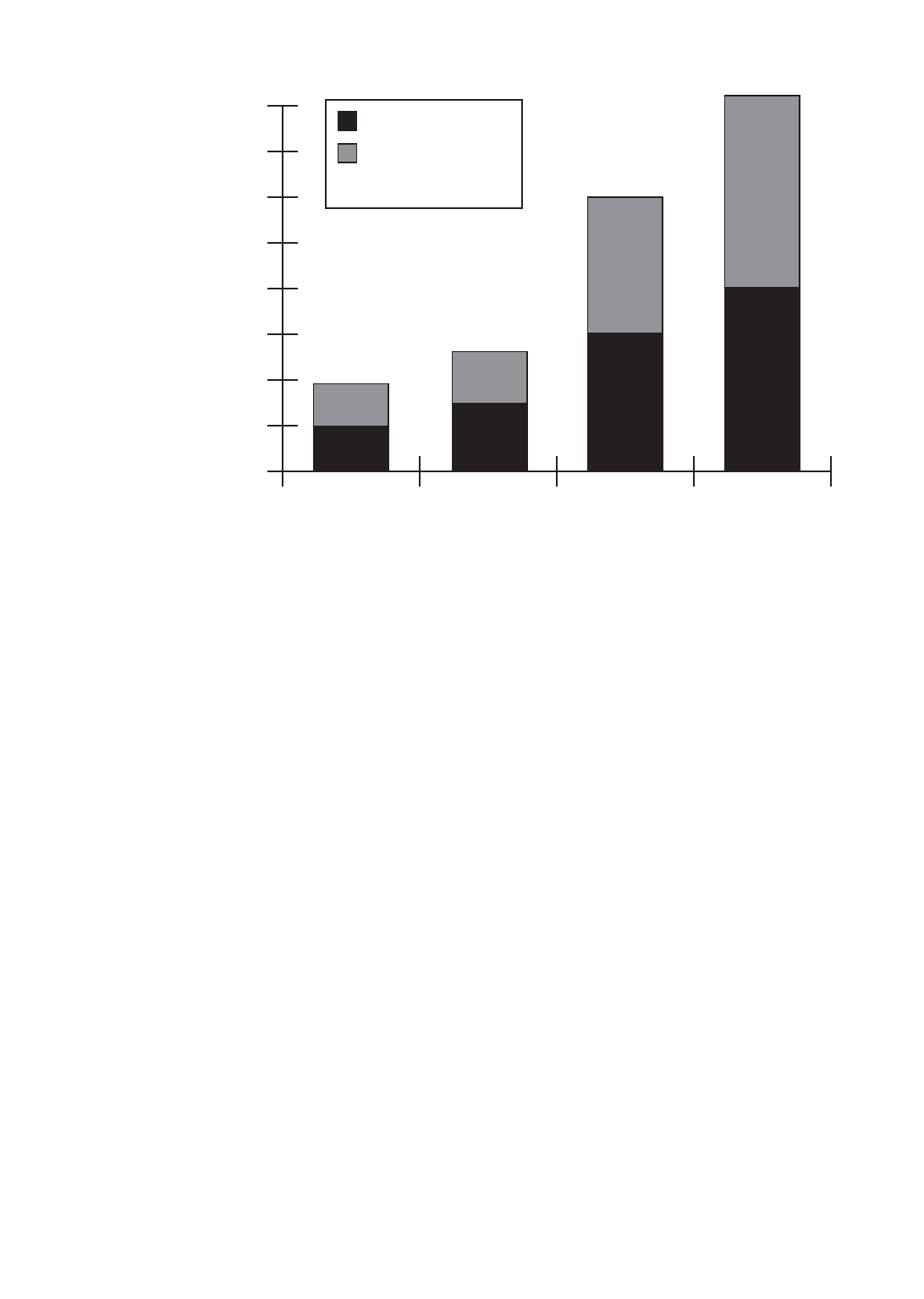
COST - Cable Tray vs. Conduit
(Equivalent Conductor Fill Areas)
Material Cost
Labor Cost @
$25/hr per NECA
labor units.
Ladder
Cable Tray
1
Solid Bottom
Cable Tray
2
EMT
3
Rigid Steel
Conduit
4
Installation: 200 linear feet of cable supported with four 90° direction changes and all
trapeze supports on 8 ft. spans.
1. Hot dip galvanized steel, 18" wide, ladder cable tray (9" rung spacing) with all hardware.
2. Hot dip galvanized steel, 18" wide, solid bottom cable tray and all hardware.
3. 7 parallel runs of 3" diameter EMT with concentric bends.
4. 7 parallel runs of 3" diameter galvanized conduit with concentric bends.
Note: Above costs are historical figures and do not include cable and cable pulling costs. Cable costs differ
per installation and cable/conductor pulling costs have been shown to be considerably less for cable
tray than for conduit.
Cooper B-Line, Inc Cable Tray Manual

•The higher the elevation of the wiring system,
the more important the number of components
required to complete the installation. Many
additional man-hours will be required just moving
the components needed for the conduit system up
to the work location.
•Conduit wiring systems require pull boxes or
splice boxes when there is the equivalent of more
than 360 degrees of bends in a run. For large
conductors, pull or junction boxes may be required
more often to facilitate the conductor’s installation.
Cable tray wiring systems do not require pull boxes
or splice boxes.
•Penetrating a masonry wall with cable tray
requires a smaller hole and limited repair work.
•More supports are normally required for rigid
steel conduit due to the requirements of NEC®
Table 344.30(B)(2).
•Concentric conduit bends for direction changes
in conduit banks are very labor intensive and difficult
to make. However if they are not used, the
installation will be unattractive. The time required to
make a concentric bend is increased by a factor of
3-6 over that of a single shot bend. This time
consuming practice is eliminated when cable tray
wiring systems are used.
•Conductor pulling is more complicated and time
consuming for conduit wiring systems than for cable
tray wiring systems. Normally, single conductor wire
pulls for conduit wiring systems require multiple reel
setups. For conduit wiring systems, it is necessary to
pull from termination equipment enclosure to
termination equipment enclosure. Tray cables being
installed in cable trays do not have to be pulled into
the termination equipment enclosures. Tray cable
may be pulled from near the first termination
enclosure along the cable tray route to near the
second termination enclosure. Then, the tray cable
is inserted into the equipment enclosures for
termination. For projects with significant numbers of
large conductors terminating in switchgear, this may
be a very desirable feature that can save hours of an
electrician's time. Unnecessary power outages can
be eliminated since tray cable pulls may be made
without de-energizing the equipment. For conduit
installations, the equipment will have to be de-
energized for rubber safety blanketing to be
installed, otherwise the conductor pulls might have
to be made on a weekend or on a holiday at
premium labor costs to avoid shutting down
production or data processing operations during
normal working hours.
•Conductor insulation damage is common in
conduits since jamming can occur when pulling the
conductors. Jamming is the wedging of conductors
in a conduit when three conductors lay side by side
in a flat plane. This may occur when pulling around
bends or when the conductors twist. Ninety-two
percent of all conductor failures are the result of the
conductor’s insulation being damaged during the
conductor’s installation. Many common
combinations of conductors and conduits fall into
critical jam ratio values. Critical jam ratio (J.R.=
Conduit ID/Conductor OD) values range from 2.8
to 3.2. The J. R. for 3 single conductor
THHN/THWN insulated 350 kcmil conductors in a
21/2inch conduit would be 3.0 (2.469 inches/
0.816 inches). If conductor insulation damage
occurs, additional costs and time are required for
replacing the conductors. This cannot occur in a
cable tray wiring system.
•Smaller electrician crews may be used to install
the equivalent wiring capacity in cable tray. This
allows for manpower leveling, the peak and average
crew would be almost the same number, and the
electrician experience level required is lower for
cable tray installations.
•Since the work is completed faster there is less
work space conflict with the other construction
disciplines. This is especially true if installations are
elevated and if significant amounts of piping are
being installed on the project.
MAINTENANCE SAVINGS
•One of the most important features of cable
tray is that tray cable can easily be installed in
existing trays if there is space available. Cable tray
wiring systems allow wiring additions or
modifications to be made quickly with minimum
disruption to operations. Any conceivable change
that is required in a wiring system can be done at
lower cost and in less time for a cable tray wiring
system than for a conduit wiring system.
7
Cable Tray Manual Cooper B-Line, Inc

•Moisture is a major cause of electrical
equipment and material failures. Breathing due to
temperature cycling results in the conduits
accumulating relatively large amounts of moisture.
The conduits then pipe this moisture into the
electrical equipment enclosures which over a period
of time results in the deterioration of the equipment
insulation systems and their eventual failure. Also,
moisture may become a factor in the corrosion
failure of some of the critical electrical equipment's
metallic components. Conduit seals are not effective
in blocking the movement of moisture. The conduit
systems may be designed to reduce the moisture
problems but not to completely eliminate it. Few
designers go into the design detail necessary to
reduce the effects of moisture in the conduit
systems. Tray cables do not provide internal
moisture paths as do conduits.
•In the event of external fires in industrial
installations, the damage to the tray cable and cable
tray is most often limited to the area of the flame
contact plus a few feet on either side of the flame
contact area. For such a fire enveloping a steel
conduit bank, the steel conduit is a heat sink and the
conductor insulation will be damaged for a
considerable distance inside the conduit.
Thermoplastic insulation may be fused to the steel
conduit and the conduit will need to be replaced for
many feet. This occurred in an Ohio chemical plant
and the rigid steel conduits had to be replaced for
90 feet. Under such conditions, the repair cost for
fire damage would normally be greater for a conduit
wiring system than for cable tray and tray cable. In
the Ohio chemical plant fire, there were banks of
conduits and runs of cable tray involved. The cable
tray wiring systems were repaired in two days. The
conduit wiring systems were repaired in six days and
required a great deal more manpower.
•In the event of an external fire, the conduit
becomes a heat sink and an oven which decreases
the time required for the conductor insulation
systems to fail. The heat decomposes the cable
jackets and the conductor insulation material. If
these materials contain PVC as do most cables,
hydrogen chloride vapors will come out the ends of
the conduits in the control rooms. These fumes are
very corrosive to the electronic equipment. They are
also hazardous to personnel. A flame impingement
on a cable tray system will not result in the fumes
going into the control room as there is no
containment path for them. They will be dispersed
into the atmosphere.
IN MOST CASES AN OBJECTIVE
EVALUATION OF THE REQUIREMENTS
FOR MOST HIGH DENSITY WIRING
SYSTEMS WILL SHOW THAT A CABLE
TRAY WIRING SYSTEM PROVIDES A
WIRING SYSTEM SUPERIOR TO A
CONDUIT WIRING SYSTEM.
Abandoned Cables
Easily identified, marked, or removed - all
possible from an open Cable Tray System
For the 2002 National Electrical Code, several
proposals were submitted to the NFPA to revise the
1999 NEC®for Articles 300, 640, 645, 725, 760,
770, 800, 820, and 830 to require all abandoned
cables to be removed from plenum spaces.
The purpose of the proposals is to remove the
cables as a source of excess combustibles from
plenums and other confined spaces such as raised
floors and drop ceilings. All of the Code Making
Panels agreed that this should be acceptable practice
except Code Making Panel 3, which oversees
Article 300.
Because Article 300 is exempt from this
requirement only low-voltage and communication
cables are affected.
Each Article adopted a definition of abandoned
cables and the rule for removal. The general
consensus is that abandoned cable is cable that is
not terminated at equipment or connectors and is
not identified for future use with a tag. Please refer
to each individual NEC®Article for specifics.
Having to tag, remove, or rearrange cables within
an enclosed raceway can be a time consuming and
difficult job. Without being able to clearly see the
cables and follow their exact routing throughout a
facility, identifying abandoned cables would be very
difficult and expensive.
With the open accessibility of cable tray, these
changes can be implemented with ease. Abandoned
cables can be identified, marked, rearranged, or
removed with little or no difficulty.
8
Cooper B-Line, Inc Cable Tray Manual
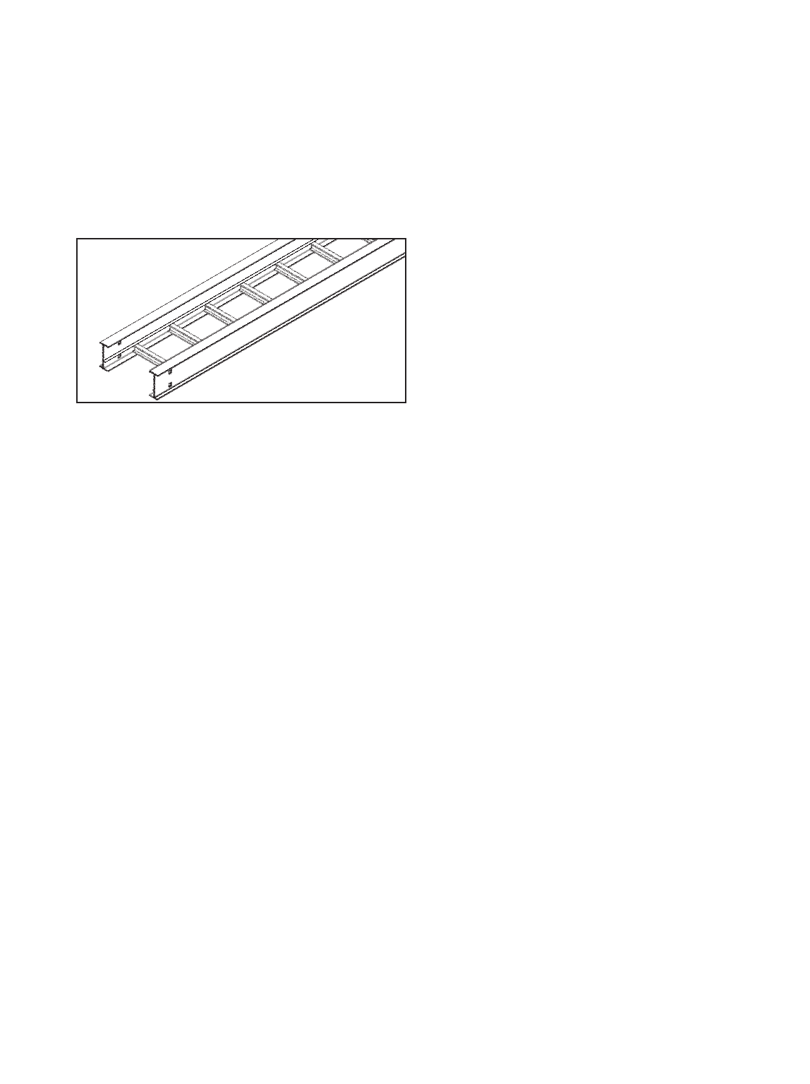
392.1. Scope.
Of the types of cable trays listed in this section,
ladder cable tray is the most widely used type of
cable tray due to several very desirable features.
•The rungs provide a convenient anchor for
tying down cables in vertical runs or where the
positions of the cables must be maintained in
horizontal runs.
•Cables may exit or enter through the top or the
bottom of the tray.
•A ladder cable tray without covers provides for
the maximum free flow of air, dissipating heat
produced in current carrying conductors.
•Moisture cannot accumulate in ladder cable
trays and be piped into electrical equipment as
happens in conduit systems.
•Ladder cable tray cannot pipe hazardous or
explosive gasses from one area to another as
happens with conduit systems.
• In areas where there is the potential for dust to
accumulate, ladder cable trays should be installed.
The dust buildup in ladder cable trays will be less
than the dust buildup in ventilated trough or solid
bottom cable trays.
Ladder cable trays are available in widths of 6, 9,
12, 18, 24, 30, 36, and 42 inches with rung
spacings of 6, 9, 12, or 18 inches. Wider rung
spacings and wider cable tray widths decrease the
overall strength of the cable tray. Specifiers should
be aware that some cable tray manufacturers do not
account for this load reduction in their published
cable tray load charts. B-Line uses stronger rungs in
wider cable trays to safely bear the loads published.
With one exception, the specifier selects the rung
spacing that he or she feels is the most desirable for
the installation. The exception is that 9 inches is the
maximum allowable rung spacing for a ladder cable
tray supporting any 1/0 through 4/0 single
conductor cables [See Section 392.3(B)(1)(a)].
Where the ladder cable tray supports small
diameter multiconductor control and
instrumentation cables; 6, 9, or 12 inch rung
spacings should be specified. Quality Type TC,
Type PLTC, or Type ITC small diameter
multiconductor control and instrumentation cables
will not be damaged due to the cable tray rung
spacing selected, but the installation may not appear
neat if there is significant drooping of the cables
between the rungs.
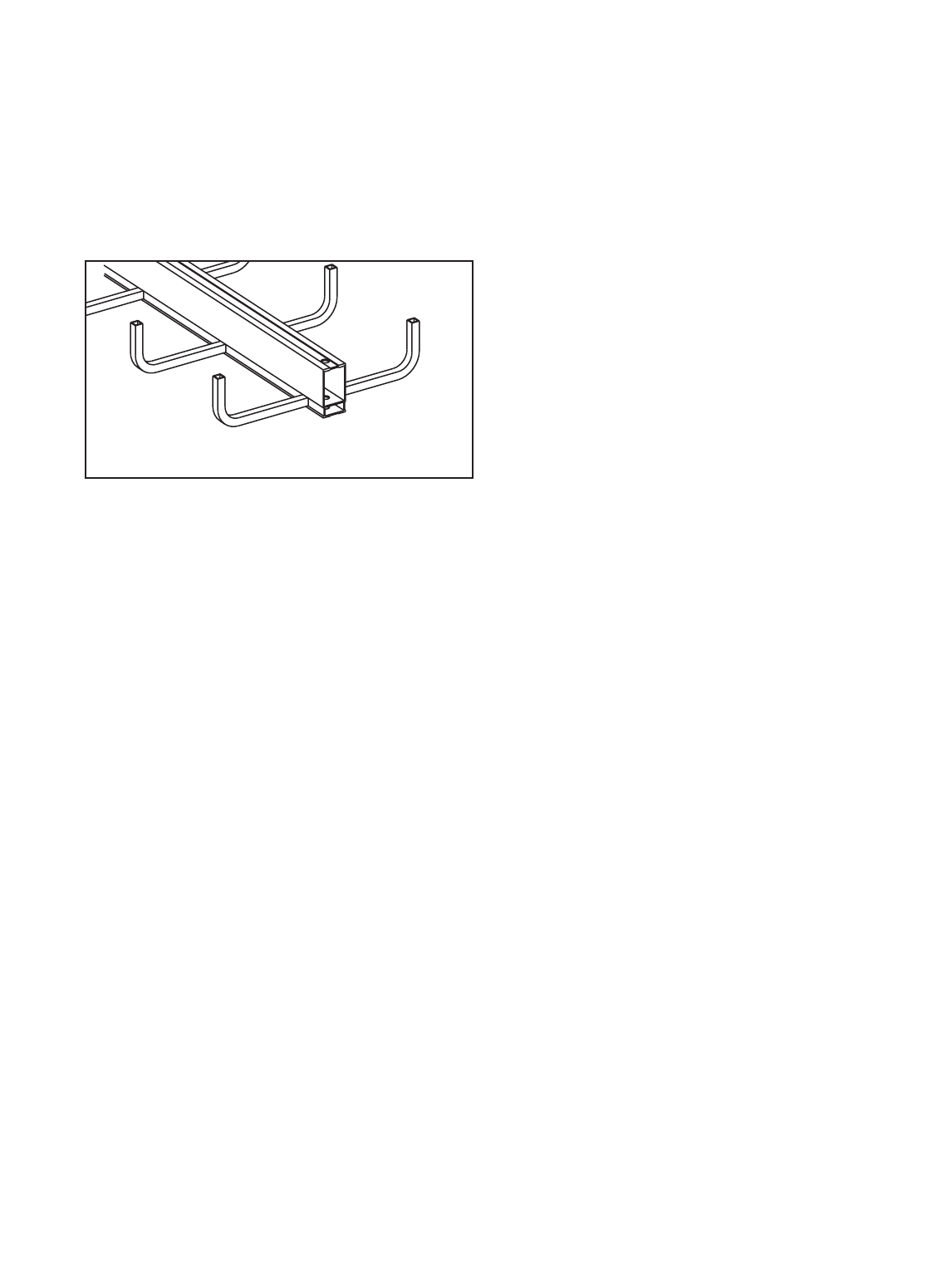
For ladder cable trays supporting large power
cables, 9 inch or wider rung spacings should be
selected. For many installations, the cable trays are
routed over the top of a motor control center (MCC)
or switchgear enclosure. Cables exit out the bottom
of the cable trays and into the top of the MCC or
switchgear enclosure. For these installations, the
cable manufacturer's recommended minimum
bending radii for the specific cables must not be
violated. If the rung spacing is too close, it may be
necessary to remove some rungs in order to
maintain the proper cable bending radii. This
construction site modification can usually be avoided
by selecting a cable tray with 12 or 18 inch rung
spacing.
If you are still uncertain as to which rung spacing
to specify, 9 inch rung spacing is the most common
and is used on 80% of the ladder cable tray sold.
9
Standard Aluminum Ladder
AN IN-DEPTH LOOK AT 2002 NEC®
ARTICLE 392 - CABLE TRAY
(The following code explanations are to be used with a copy of the 2002 NEC®.)
To obtain a copy of the NEC®contact:
National Fire Protection Association®
1 Batterymarch Park • P.O. Box 9101
Quincy, Massachusetts 02269-9101
1-800-344-3555
Cable Tray Manual Cooper B-Line, Inc
The 1999 NEC®added the word ‘ventilated’ in
front of trough to clear up some confusion that solid
trough is treated the same as ventilated trough. It is
not. Solid trough is recognized as solid bottom cable
tray.
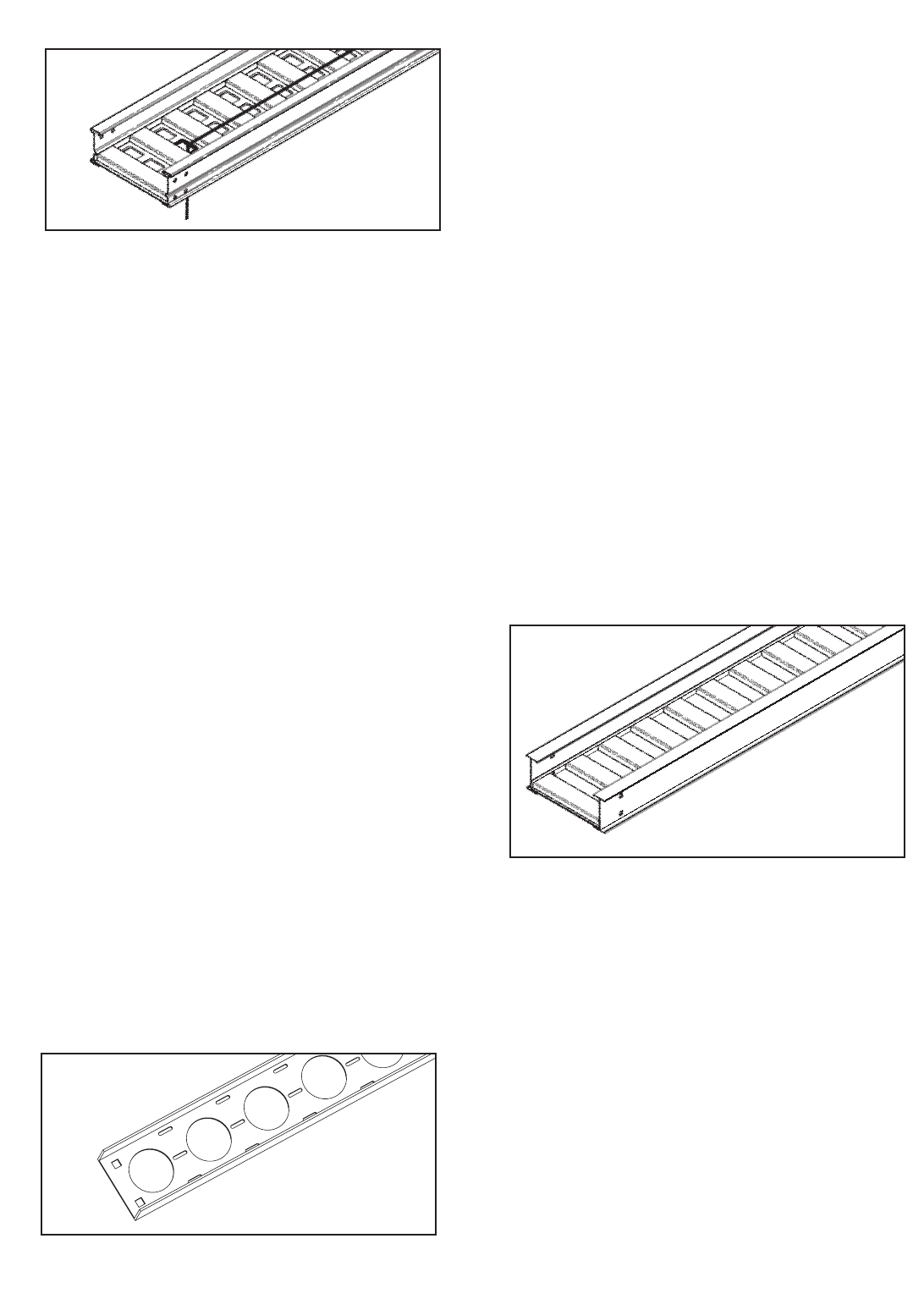
Ventilated trough cable tray is often used when the
specifier does not want to use ladder cable tray to
support small diameter multiconductor control and
instrumentation cables. As no drooping of the small
diameter cables is visible, ventilated trough cable
trays provide neat appearing installations. Small
diameter cables may exit the ventilated trough cable
tray through the bottom ventilation holes as well as
out the top of the cable tray. For installations where
the cables exit the bottom of the cable tray and the
system is subject to some degree of vibration, it is
advisable to use B-Line Trough Drop-Out Bushings
(Cat. No. 99-1124). These snap-in bushings provide
additional abrasion protection for the cable jackets.
Just as for ladder cable tray, ventilated trough cable
tray will not pipe moisture into electrical equipment.
Standard widths for ventilated trough cable tray
systems are 6, 9, 12, 18, 24, 30, and 36 inches.
The standard bottom configuration for ventilated
trough cable tray is a corrugated bottom with 2 7/8
inch bearing surfaces - 6 inches on centers and 2
1/4inch x 4 inch ventilation openings. Since a
corrugated bottom cannot be bent horizontally, the
standard bottom configuration for horizontal bend
fittings consists of rungs spaced on 4 inch centers.
This difference in bottom construction may be
objectionable to some owners, so be sure you are
aware of the owner's sensitivity to aesthetics for the
cable tray installation.
Channel cable tray systems (B-Line's cable
channel) are available in 3, 4, and 6 inch widths
with ventilated or solid bottoms. The 2002 NEC®
now recognizes solid bottom cable channel.
Prior to the 2002 Code, the NEC®did not have
any specific provisions for the use of solid cable
channel.
Instead of large conduits, cable channel may be
used very effectively to support cable drops from the
cable tray run to the equipment or device being
serviced and is ideal for cable tray runs involving a
small number of cables. Cable channel may also be
used to support push buttons, field mounted
instrumentation devices, etc. Small diameter cables
may exit ventilated cable channel through the
bottom ventilation holes, out the top or through the
end. For installations where the cables exit through
the ventilation openings and the cable channel or
the cables are subject to some degree of vibration, it
is advisable to use B-Line Cable Channel Bushings
(Cat. No. 99-1125). These snap-in plastic bushings
provide additional abrasion protection for the cable
jackets.
Some specifiers prefer solid bottom cable tray to
support large numbers of small diameter control and
multiconductor instrumentation cables. Solid bottom
steel cable trays with solid covers and wrap around
cover clamps can be used to provide EMI/RFI
shielding protection for sensitive circuits.
Unlike ladder and ventilated trough cable trays,
solid bottom cable trays can collect and retain
moisture. Where they are installed outdoors or
indoors in humid locations and EMI/RFI shielding
protection is not required, it is recommended that
1/4inch weep holes be drilled in their bottoms at
the sides and in the middle every 3 feet to limit
water accumulation.
10
Vent. Channel Cable Tray
(B-Line's Cable Channel)
Aluminum Solid Bottom Trough
Cooper B-Line, Inc Cable Tray Manual
Steel Ventilated Trough
The words "and other similar structures." were
incorporated in Section 392.1 for future types of
cable tray that might be developed, such as center
supported type cable tray. All the technical
information developed by the 1973 NEC®
Technical Subcommittee on Cable Tray for Article
318 - Cable Trays was based on cable trays with
side rails and this technical information is still the
basis for the 2002 NEC®Article 392 - Cable Trays.
The standard lengths for cable trays are 10, 12,
20 and 24 feet (consult B-Line for the availability of
nonstandard cable tray lengths). Selecting a cable
tray length is based on several criteria. Some of
these criteria include the required load that the cable
tray must support, the distance between the cable
tray supports, and ease of handling and installation.
One industry standard that is strongly
recommended is that only one cable splice be
placed between support spans and, for long
span trays, that they ideally be place at 1/4-span.
This automatically limits the length of tray you
choose, as the tray must be longer than or equal to
the support span you have selected. Matching the
tray length to your support span can help ensure
that your splice locations are controlled.
Cable trays can be organized into 4 categories:
Short Span, Intermediate Span, Long Span, and
Extra-Long Span.
Short Span trays, typically used for non-industrial
indoor installations, are usually supported every 6 to
8 feet, while Intermediate Span trays are typically
supported every 10 to 12 feet. A 10 or 12 foot
cable tray is usually used for both of these types of
installations. To keep from allowing two splices to
occur between supports, a 12 foot tray should be
used for any support span greater than 10 feet, up
to 12 feet. Placing the cable tray splices at 1/4-span
is not critical in a short or intermediate span
application given that most trays have sufficiently
strong splice plates.
In an indoor industrial installation 10 or 12 foot
tray sections may be easier to handle and install as
you may have piping or ducting to maneuver
around. However, using 20 foot instead of 12 foot
straight sections may provide labor savings during
installation by reducing the number of splice joints.
If this is done, the selected tray system should meet
the loading requirements for the support span you
are using. If you are interested in supporting 100
lbs/ft and you are buying 20 foot tray sections while
supporting it every 12 feet, it isn’t necessary to
specify a NEMA 20C tray (100 lbs/ft on a 20 foot
span). A NEMA 20A tray (50 lbs/ft on a 20 foot
span) will support over 130 lbs/ft when supported
on a 12 ft span with a safety factor of 1.5.
Specifying a 20C tray is not an economical use of
product. If you desire to use 20 foot sections of
cable tray, it makes more sense to increase your
support span up to 20 feet. This not only saves
labor by decreasing the number of splices, but also
by decreasing the number of supports that must be
installed.
Long Span trays are typically supported anywhere
from 14 to 20 foot intervals with 20 feet being the
most popular. In long span situations, the placement
of the splice locations at 1/4-span becomes much
more important. Matching the tray length to your
support span can help control your splice locations.
Extra-Long Span trays are supported on spans
exceeding 20 feet. Some outdoor cable tray
installations may have to span anywhere from 20 to
30 feet to cross roads or to reduce the number of
expensive outdoor supports. The distance between
supports affects the tray strength exponentially;
therefore the strength of the cable tray system
selected should be designed around the specific
support span chosen for that run.
[See Section 392.5(A) on page 18 for additional
information on cable tray strength and rigidity.]
B-Line has many cataloged fittings and accessory
items for ladder, ventilated trough, ventilated
channel, and solid bottom cable trays which
eliminate the need for the costly field fabrication of
such items. When properly selected and installed,
these factory fabricated fittings and accessories
improve the appearance of the cable tray system in
addition to reducing labor costs.
11
Cable Tray Manual Cooper B-Line, Inc
Center Supported Cable Tray
(B-Line’s Cent-R-Rail System)

Cable Tray Materials
Metallic cable trays are readily available in aluminum,
pregalvanized steel, hot-dip galvanized after
fabrication, and stainless steel. Aluminum cable tray
should be used for most installations unless specific
corrosion problems prohibit its use. Aluminum's light
weight significantly reduces the cost of installation
when compared to steel.
A fine print note has been added in the 2002 NEC®
that references the National Electrical Manufacturers
Association (NEMA) documents for further
information on cable tray. These documents: NEMA
VE-1, Metal Cable Tray Systems; NEMA VE-2,
Cable Tray Installation Guidelines; and NEMA FG-1,
Non Metallic Cable Tray Systems, are an excellent
industry resource in the application, selection, and
installation of cable trays both metallic and non
metallic. Contact Cooper B-Line for more
information concerning these helpful documents.
392.2. Definition. Cable Tray System.
This section states that cable tray is a rigid
structural support system used to securely fasten or
support cables and raceways. Cable trays are not
raceways. Cable trays are mechanical supports just
as strut systems are mechanical supports. NEC®
Article 392 - Cable Trays is an article dedicated to a
type of mechanical support. It is very important that
the personnel involved with engineering and
installing cable tray utilize it as a mechanical support
system and not attempt to utilize it as a raceway
system. There are items in the NEC®that apply to
raceways and not to cable tray. There are also items
in the NEC®that apply to cable tray and not to
raceways. These differences will be covered at the
appropriate locations in this manual.
392.3. Uses Permitted. Cable tray
installations shall not be limited to
industrial establishments.
The text in Section 392.3 clearly states that cable
tray may be used in non-industrial establishments.
The use of cable tray should be based on sound
engineering and economic decisions.
For clarity, the NEC®now lists all types of circuits
to explicitly permit their use in cable trays. These
circuit types include: services, feeders, branch
circuits, communication circuits, control circuits, and
signaling circuits.
The 2002 NEC®also added a new requirement
that where cables in tray are exposed to the direct
rays of the sun, they shall be identified as sunlight
resistant for all occupancies, not just industrial.
392.3. Uses Permitted. (A) Wiring
Methods.
This section identifies the 300 & 600 volt
multiconductor cables that may be supported by
cable tray. The "Uses Permitted" or "Uses Not
Permitted" sections in the appropriate NEC®cable
articles provide the details as to where that cable
type may be used. Where the cable type may be
used, cable tray may be installed to support it except
as per Section 392.4 which states that cable trays
shall not be installed in hoistways or where subject
to severe physical damage. Where not subject to
severe physical damage, cable tray may be used in
any hazardous (classified) area to support the
appropriate cable types in accordance with the
installation requirements of the various Articles that
make up NEC® Chapter 5 or in any non-hazardous
(unclassified) area.
It should be noted that Section 300.8 of
the NEC®states that cable trays containing
electric conductors cannot contain any other
service that is not electrical. This includes
any pipe or tube containing steam, water, air,
gas or drainage.
For commercial and industrial cable tray wiring
systems: Type ITC, Type MC, Type TC, and Type
PLTC multiconductor cables are the most commonly
used cables. Type MI and Optical-Fiber cables are
special application cables that are desirable cables
for use in some cable tray wiring systems. The
following paragraphs provide information and
comments about these cable types.
Type MI Cable: Mineral-Insulated, Metal
Sheathed Cable (Article 332). This cable has a
liquid and gas tight continuous copper sheath over
its copper conductors and magnesium oxide
insulation. Developed in the late 1920's by the
French Navy for submarine electrical wiring systems,
properly installed MI cable is the safest electrical
wiring system available. In Europe, Type MI cable
has had a long, successful history of being installed
(with PVC jackets for corrosion protection) in cable
trays as industrial wiring systems. This cable may be
installed in hazardous (classified) areas or in non-
hazardous (unclassified) areas. The single limitation
12
Cooper B-Line, Inc Cable Tray Manual

on the use of Type MI cable is that it may not be
used where it is exposed to destructive corrosive
conditions unless protected by materials suitable for
the conditions. Type MI cable without overall
nonmetallic coverings may be installed in ducts or
plenums used for environmental air and in other
space used for environmental air in accordance with
Sections 300.22(B) and (C). Cable tray may be
installed as a support for Type MI cable in any
location except where the cable is installed in a
hoistway. Section 332-30 states that MI cable shall
be securely supported at intervals not exceeding 6
feet (1.83 m). Type MI cable has a UL two hour fire
resistive rating when properly installed. An
installation requirement for this rating is that the
cable be securely supported every 3 feet. Steel or
stainless steel cable trays should be used to support
Type MI cable being used for critical circuit service.
During severe fire conditions, steel or stainless steel
cable tray will remain intact and provide support
longer than aluminum or fiberglass reinforced plastic
cable trays.
Type MC Cable: Metal-clad cable (Article 330).
There are large amounts of Type MC cable installed
in industrial plant cable tray systems. This cable is
often used for feeder and branch circuit service and
provides excellent service when it is properly
installed. The metallic sheath may be interlocking
metal tape or it may be a smooth or corrugated
metal tube. A nonmetallic jacket is often extruded
over the aluminum or steel sheath as a corrosion
protection measure. Regular MC cable, without
nonmetallic sheath, may be supported by cable tray
in any hazardous (classified) area except Class I and
Class II, Division 1 areas. For Type MC cables to
qualify for installation in Class I and Class II Division
I areas (Section 501-4(A) (1) (c&d), they must have a
gas/vapor tight continuous corrugated aluminum
sheath with a suitable plastic jacket over the sheath.
They must also contain equipment grounding
conductors and listed termination fittings must be
used where the cables enter equipment. Type MC
Cable employing an impervious metal sheath
without overall nonmetallic coverings may be
installed in ducts or plenums used for environmental
air in accordance with Section 300.22(B) and may
be installed in other space used for environmental
air in accordance with Section 300.22(C). The
maximum support spacing is 6 feet (1.83 m).
Type TC Cable: Power and control tray cable
(Article 336). This cable type was added to the
1975 NEC®(as an item associated with the revision
of Article 318-Cable Trays). Type TC cable is a
multiconductor cable with a flame retardant
nonmetallic sheath that is used for power, lighting,
control, and signal circuits. It is the most common
cable type installed in cable tray for 480 volt
feeders, 480 volt branch circuits, and control
circuits. Where Type TC cables comply with the
crush and impact requirements of Type MC cable
and is identified for such use, they are permitted as
open wiring between a cable tray and the utilization
equipment or device. In these instances where the
cable exits the tray, the cable must be supported and
secured at intervals not exceeding 6 feet (See
Section 336.10(6)). The service record of UL listed
Type TC cable where properly applied and installed
has been excellent.
For those installations where the NEC®allows its
use, a cost savings is realized by using Type TC
cables instead of Type MC cables. Type TC cable
may be installed in cable tray in hazardous
(classified) industrial plant areas as permitted in
Articles 392, 501, 502, 504 and 505 provided the
conditions of maintenance and supervision assure
that only qualified persons will service the
installation [See Section 336.10(3)].
Where a cable tray wiring system containing Type
TC cables will be exposed to any significant amount
of hot metal splatter from welding or the torch
cutting of metal during construction or maintenance
activities, temporary metal or plywood covers should
be installed on the cable tray in the exposure areas
to prevent cable jacket and conductor insulation
damage. It is desirable to use only quality Type TC
cables that will pass the IEEE 383 and UL Vertical
Flame Tests (70,000 BTU/hr). Type TC cable
assemblies may contain optical fiber members as per
the UL 1277 standard.
Type ITC Cable: Instrumentation Tray Cable
(Article 727). Although this was a new cable article
in the 1996 NEC®, it is not a new type of cable.
Thousands of miles of ITC cable have been installed
in industrial situations since the early 1960’s. This
is a multiconductor cable that most often has a
nonmetallic jacket. The No. 22 through No. 12
insulated conductors in the cables are 300 volt
rated. A metallic shield or a metallized foil shield
with a drain wire usually encloses the cable’s
conductors. These cables are used to transmit the
low energy level signals associated with the industrial
13
Cable Tray Manual Cooper B-Line, Inc

instrumentation and data handling systems. These
are very critical circuits that impact on facility safety
and on product quality. Type ITC cable must be
supported and secured at intervals not exceeding 6
feet [See Section 727.4].
Type ITC Cable may be installed in cable trays in
hazardous (classified) areas as permitted in Articles
392, 501, 502, 504 and 505. It states in Article
727 that Type ITC cables that comply with the
crush and impact requirements of Type MC cable
and are identified for such use, are permitted as
open wiring in lengths not to exceed 50 ft. between
a cable tray and the utilization equipment or device.
Where a cable tray wiring system containing Type
ITC cables will be exposed to any significant amount
of hot metal splatter from welding or the torch
cutting of metal during construction or maintenance
activities, temporary metal or plywood covers should
be installed on the cable tray to prevent cable jacket
or conductor insulation damage. It is desirable to use
only quality Type ITC cables that will pass the IEEE
383 and UL Vertical Flame Tests (70,000BTU/hr).
Type PLTC Cable: Power-Limited Tray Cable
(Sections 725-61(C), and 725-71(E)). This is a
multiconductor cable with a flame retardant
nonmetallic sheath. The No. 22 through No. 12
insulated conductors in the cables are 300 volt
rated. A metallic shield or a metallized foil shield
with drain wire usually encloses the cable's
conductors. This cable type has high usage in
communication, data processing, fire protection,
signaling, and industrial instrumentation wiring
systems.
There are versions of this cable with insulation and
jacket systems made of materials with low smoke
emission and low flame spread properties which
make them desirable for use in plenums. In
Industrial Establishments where the conditions of
maintenance and supervision ensure that only
qualified persons service the installation and where
the cable is not subject to physical damage Type
PLTC cable may be installed in cable trays
hazardous (classified) areas as permitted in Section
501.4(B), 502.4(B) and 504.20. Type PLTC cables
that comply with the crush and impact requirements
of Type MC cable and are identified for such use,
are permitted as open wiring in lengths not to
exceed a total of 50 ft. between a cable tray and the
utilization equipment or device. In this situation, the
cable needs to be supported and secured at intervals
not exceeding 6 ft. Where a cable tray wiring system
containing Type PLTC cables will be exposed to any
significant amount of hot metal splatter from
welding or the torch cutting of metal during
construction or maintenance activities, temporary
metal or plywood covers should be installed on the
cable tray to prevent cable jacket and conductor
insulation damage. It is desirable to use only quality
Type PLTC cables that will pass the IEEE 383 and
UL Vertical Flame Tests (70,000 BTU/hr). Type
PLTC cable assemblies may contain optical fiber
members as per the UL 1277 standard.
Optical Fiber Cables (Article 770). The addition
of optical fiber cables in the Section 392.3(A) cable
list for the 1996 NEC was not a technical change.
Optical fiber cables have been allowed to be
supported in cable trays as per Section 770.6.
Optical fibers may also be present in Type TC
cables as per UL Standard 1277.
For the 1999 NEC®code, Article 760 - Fire
Alarm Cables and Articles 800 - Multipurpose and
Communications Cables were added to the list of
cables permitted to be installed in cable tray
systems.
For the 1993 NEC®, the general statement in the
1990 NEC®which allowed all types of raceways to
be supported by cable trays was replaced by
individual statements for each of the ten specific
raceway types that may now be supported by cable
tray. The chances of any such installations being
made are very low, since strut is a more convenient
and economic choice than cable tray to support
raceway systems.
392.3. Uses Permitted. (B) In Industrial
Establishments.
This section limits the installation of single
conductor cables and Type MV multiconductor
cables in cable trays to qualifying industrial
establishments as defined in this section.
Per the 2002 NEC®solid bottom cable trays are
now permitted to support single conductor cables
only in industrial establishments where conditions of
maintenance and supervision ensure that only
qualified persons will service the installed cable tray
system. However, at this time, no fill rules for single
conductor cables in solid bottom cable tray have
been established. [see Section 392.3(B)]
14
Cooper B-Line, Inc Cable Tray Manual

392.3. Uses Permitted. (B) In Industrial
Establishments. (1) Single Conductor.
Section 392.3(B)(1) covers 600 volt and Type MV
single conductor cables.
There are several sections which cover the
requirements for the use of single conductor cables
in cable tray even though they only comprise a small
percentage of cable tray wiring systems. Such
installations are limited to qualifying industrial
facilities [See Section 392.3(B)]. Many of the facility
engineers prefer to use three conductor power
cables. Normally, three conductor power cables
provide more desirable electrical wiring systems than
single conductor power cables in cable tray (See
Section 392.8. Cable installation - three conductor vs. single
conductor cables).
392.3(B)(1)(a)
Single conductor cable shall be No. 1/0 or larger
and shall be of a type listed and marked on the
surface for use in cable trays. Where Nos. 1/0
through 4/0 single conductor cables are used, the
maximum allowable rung spacing for ladder cable
tray is 9 inches.
392.3(B)(1)(b)
Welding cables shall comply with Article 630, Part
IV which states that the cable tray must provide
support at intervals not to exceed 6 inches. A
permanent sign must be attached to the cable tray
at intervals not to exceed 20 feet. The sign must
read “CABLE TRAY FOR WELDING CABLES
ONLY”.
392.3(B)(1)(c)
This section states that single conductors used as
equipment grounding conductors (EGCs) in cable
trays shall be No. 4 or larger insulated, covered or
bare.
The use of a single conductor in a cable tray as
the EGC is an engineering design option. Section
300.3(B) states that all conductors of the same
circuit and the EGC, if used, must be contained
within the same cable tray.
The other options are to use multiconductor
cables that each contain their own EGC or to use
the cable tray itself as the EGC in qualifying
installations [see Section 392.3(C)]
If an aluminum cable tray is installed in a moist
environment where the moisture may contain
materials that can serve as an electrolyte, a bare
copper EGC should not be used. Under such
conditions, electrolytic corrosion of the aluminum
may occur. For such installations, it is desirable to
use a low cost 600 volt insulated conductor and
remove the insulation where connections to
equipment or to equipment grounding conductors
are made. (See Section 392.7. Grounding, for additional
information on single conductors used as the EGC for cable
tray systems).
392.3. Uses Permitted. (B) In Industrial
Establishment (2) Medium Voltage.
Single and multiconductor type MV cables (Article
328) must be sunlight resistant if exposed to direct
sunlight. Single conductors shall be installed in
accordance with 392.3(B)(1)
392.3. Uses Permitted. (C) Equipment
Grounding Conductors.
Cable tray may be used as the EGC in any
installation where qualified persons will service the
installed cable tray system. There is no restriction as
to where the cable tray system is installed. The
metal in cable trays may be used as the EGC as per
the limitations of table 392.7(B)(2). See Section
392.7. Grounding in this manual for additional
information on the use of cable trays as the EGC.
392.3. Uses Permitted. (D) Hazardous
(Classified) Locations.
This section states that if cable tray wiring systems
are installed in hazardous (classified) areas, the
cables that they support must be suitable for
installation in those hazardous (classified) areas. The
cable carries the installation restriction. The
installation restriction is not on the cable tray except
that the cable tray installations must comply with
Section 392.4. The following is an explanation of
the parts of the code which affect the use of cable
tray in hazardous locations.
501.4. Wiring Methods - Listed Termination
Fittings. (A) Class I, Division 1 (Gases or Vapors).
501-4(A)(1)(b) Type MI cable may be installed in
cable tray in this type of hazardous (classified) area.
501-4(A)(1)(c) allows Type MC-HL cables to be
installed in Class I, Division I areas if they have a
gas/vapor tight continuous corrugated aluminum
sheath with a suitable plastic jacket over the sheath.
They must also contain equipment grounding
conductors sized as per Section 250.122 and listed
termination fittings must be used where the cables
enter equipment.
15
Cable Tray Manual Cooper B-Line, Inc

501-4(A)(1)(d) allows Type ITC-HL cable to be
installed in Class I, Division I areas if they have a
gas/vapor tight continuous corrugated aluminum
sheath with a suitable plastic jacket over the sheath
and provided with termination fittings listed for the
application.
501.4. Wiring Methods. (B) Class I, Division 2
(Gases or Vapors). Types ITC, PLTC, MI, MC, MV,
or TC cables may be installed in cable tray in this
type of hazardous (classified) area. Under the
conditions specified in Section 501.5(E), Cable seals
are required in Class 1, Division 2 areas. Cable seals
should be used only when absolutely necessary.
501.5. Sealing and Drainage. (E) Cable Seals,
Class 1, Division 2. (1) Cables will be required to be
sealed only where they enter certain types of
enclosures used in Class 1, Division 2 areas. Factory
sealed push buttons are an example of enclosures
that do not require a cable seal at the entrance of
the cable into the enclosure.
501.5. Sealing and Drainage. (E) Cable Seals,
Class 1, Division 2. (2) Gas blocked cables are
available from some cable manufacturers but they
have not been widely used. For gas to pass through
the jacketed multiconductor cable's core, a pressure
differential must be maintained from one end of the
cable to the other end or to the point where there is
a break in the cable's jacket. The existence of such a
condition is extremely rare and would require that
one end of the cable be in a pressure vessel or a
pressurized enclosure and the other end be exposed
to the atmosphere. The migration of any significant
volume of gas or vapor though the core of a
multiconductor cable is very remote. This is one of
the safety advantages that cable tray wiring systems
have over conduit wiring systems. There are
documented cases of industrial explosions caused by
the migration of gases and vapors through conduits
when they came in contact with an ignition source.
There are no known cases of cables in cable tray
wiring systems providing a path for gases or vapors
to an ignition source which produced an industrial
explosion.
501.5. Sealing and Drainage. (E) Cable Seals,
Class 1, Division 2. (3)
Exception: Cables with an unbroken gas/vapor-
tight continuous sheath shall be permitted to pass
through a Class 1, Division 2 location without
seals.
This is an extremely important exception stating
that cable seals are not required when a cable goes
from an unclassified area through a classified area
then back to an unclassified area.
501.5. Sealing and Drainage. (E) Cable Seals,
Class 1, Division 2. (4)
If you do not have a gas/vapor-tight continuous
sheath, cable seals are required at the boundary of
the Division 2 and unclassified location.
The sheaths mentioned above may be fabricated
of metal or a nonmetallic material.
502.4. Wiring Methods. (A) Class II, Division 1
(Combustible Dusts). Type MI cable may be
installed in cable tray in this type of hazardous
(classified) area.
The Exception allows Type MC cables to be
installed in Class II, Division 1 areas if they have a
gas/vapor tight continuous corrugated aluminum
sheath with a suitable plastic jacket over the sheath.
They must also contain equipment grounding
conductors sized as per Section 250.122 and listed
termination fittings must be used where the cables
enter equipment.
502.4. Wiring Methods. (B) Class II, Division 2
(Combustible Dusts).
This section states:
Type ITC and PLTC cables may be installed in
ladder or ventilated cable trays following the same
practices as used in non-hazardous (unclassified)
areas. No spacing is required between the ITC or
PLTC cables. This is logical as the ITC and PLTC
cable circuits are all low energy circuits which do not
produce any significant heat or heat dissipation
problems.
Type MC, MI and TC [See Section 336.4(3)] cables
may be installed in ladder, ventilated trough, or
ventilated cable channel, but they are not allowed to
be installed in solid bottom cable trays.
Required Spacing in Cable Trays for Type MC, MI & TC
Cables in Class II, Division 2 Hazardous (Classified) Areas
16
Cooper B-Line, Inc Cable Tray Manual
D1 D1 D2 D2 D3
D2 D1 D1 D1

Note 1. The cables are limited to a single layer
with spacing between cables equal to the diameter
of the largest adjacent cable. This means that the
cables must be tied down at frequent intervals in
horizontal as well as vertical cable trays to maintain
the cable spacing. A reasonable distance between
ties in the horizontal cable tray would be
approximately 6 feet (See Section 392.8 Cable
Installation - Tying cables to cable trays).
Note 2. Spacing the cables a minimum of 1 inch
from the side rails to prevent dust buildup is
recommended. This is not an NEC requirement but
a recommended practice.
Where cable tray wiring systems with current
carrying conductors are installed in a dust
environment, ladder type cable trays should be used
since there is less surface area for dust buildup than
in ventilated trough cable trays. The spacing of the
cables in dust areas will prevent the cables from
being totally covered with a solid dust layer. In dusty
areas, the top surfaces of all equipment, raceways,
supports, or cable jacket surfaces where dust layers
can accumulate will require cleanup housekeeping at
certain time intervals. Good housekeeping is
required for personnel health, personnel safety and
facility safety. Excessive amounts of dust on
raceways or cables will act as a thermal barrier
which may not allow the power and lighting
insulated conductors in a raceway or cable to safely
dissipate internal heat. This condition may result in
the accelerated aging of the conductor insulation. A
cable tray system that is properly installed and
maintained will provide a safe dependable wiring
system in dust environments.
Exception: Type MC cable listed for use in Class
II,Division I locations shall be permitted to be
installed without the above spacing limitations. This
was a new exception for the 1999 NEC®code.
For this type of wiring there is no danger of the
cables being overheated when covered with dust.
The current flow in these circuits is so low that the
internally generated heat is insufficient to heat the
cables and cable spacing is not a necessity. Even
under such conditions, layers of dust should not be
allowed to accumulate to critical depths as they may
be ignited or explode as the result of problems
caused by other than the electrical system.
502.4(B)(3). Nonincendive Field Wiring
Wiring in nonincendive circuits shall be permitted
using any of the wiring methods suitable for wiring
in ordinary locations.
503.3. Wiring Methods. (A) Class III, Division 1
and (B) Class III, Division 2 (Ignitable Fibers or
Flyings). Type MI or MC cables may be installed in
cable tray in these types of hazardous (classified)
areas. The installations should be made using
practices that minimize the build-up of materials in
the trays. This can be done by using ladder cable
tray with a minimum spacing between the cables
equal to the diameter of the largest adjacent cable.
In some cases, a greater spacing between cables
than that based on the cable diameters might be
desirable depending on the characteristics of the
material that requires the area to be classified. Here
again, it must be emphasized that good
housekeeping practices are required for all types of
wiring systems to insure the safety of the personnel
and the facility.
504.20. Wiring Methods. This section allows
intrinsically safe wiring systems to be installed in
cable trays in hazardous (classified) areas. Section
504.30 specifies the installation requirements for
intrinsically safe wiring systems that are installed in
cable trays. Section 504.70 specifies the sealing
requirements for cables that may be part of a cable
tray wiring system. Section 504.80(B) states that
cable trays containing intrinsically safe wiring must
be identified with permanently affixed labels.
Cable trays are ideal for supporting both
intrinsically safe and nonintrinsically safe cable
systems as the cables may be easily spaced and tied
in position or a standard metallic barrier strip may
be installed between the intrinsically and
nonintrinsically safe circuits.
505.15. Wiring Methods. This section was
added to the 2002 NEC®to explicitly permit cable
trays in hazardous areas classified by the
international zone system, if the cables comply with
the cable requirements for zone locations.
392.3. Uses Permitted. (E) Nonmetallic
Cable Tray.
There are limited numbers of applications where
nonmetallic cable trays might be preferred over
metallic cable trays for electrical safety reasons
and/or for some corrosive conditions. An example
of an electrical safety application would be in an
electrolytic cell room. Here, the amperages are very
high and significant stray current paths are present.
Under such conditions, there is the possibility for a
17
Cable Tray Manual Cooper B-Line, Inc

high amperage short circuit if a low resistance
metallic path (metallic cable tray or metallic raceway)
is present [See information under Section 392.5(F)
Nonmetallic Cable Trays].
392.4. Uses Not Permitted.
This is the only place in the NEC®where all the
various types of cable tray have limitations on their
place of use. No cable trays can be used in
hoistways or where subject to severe physical
damage. The designer must identify the zones of
installation where a cable tray might be subjected to
severe physical damage. Usually such areas are
limited and provisions can be made to protect the
cable tray by relocating it to a more desirable
location or as a last resort to provide protection
using the appropriate structural members.
The second sentence of Section 392.4 states that
cable tray shall not be used in environmental air
spaces except to support the wiring methods
recognized for use in such spaces. This is not a
restriction on cable tray as long as it is used as a
support for the appropriate cable types.
Metallic cable trays may support cable types
approved for installation in Ducts or Plenums Used
for Environmental Air as per Section 300.22(B) and
the cable types approved for installation in Other
Space Used for Environmental Air as per Section
300.22(C).
The second sentence of Section 300.22(C)(1) is as
follows:
Other types of cables and conductors shall
be installed in electrical metallic tubing,
flexible metallic tubing, intermediate metal
conduit, rigid metal conduit without an
overall nonmetallic covering, flexible metal
conduit, or, where accessible, surface metal
raceway or metal wireway with metal covers
or solid bottom metal cable tray with solid
metal covers.
Reprinted with permission from NFPA 70-1999, the National Electrical Code®,
Copyright© 1998, National Fire Protection Association, Quincy, MA 02269. This reprinted
material is not the complete and official position of the National Fire Protection Association,
on the referenced subject which is represented only by the standard in its entirety.
This part of Section 300.22(C) is confusing. The
statement as underlined in the above paragraph
leads some to assume, for installations in Other
Spaces Used for Environmental Air, that the types
of insulated single conductors which are installed in
raceway installations may also be installed in solid
bottom metal cable trays with metal covers. This is
not so. Only the appropriate multiconductor cable
types as per Section 392.3(A) may be installed in
solid bottom cable trays.
Cable tray may be used to support data process
wiring systems in air handling areas below raised
floors as per Sections 300.22(D) and 800.52(D).
392.5. Construction Specifications. (A)
Strength and Rigidity.
The designer must properly select a structurally
satisfactory cable tray for their installation. This
selection is based on the cable tray's strength, the
cable tray loading and the spacing of the supports.
The NEMA Metallic Cable Tray Systems Standard
Publication VE-1 contains the cable tray selection
information and it is duplicated in B-Line's Cable
Tray Systems Catalog.
The NEMA Standard provides for a static load
safety factor of 1.5. A number (Span in Feet - the
distance between supports) and letter (Load in lbs/ft)
designation is used to properly identify the cable
tray class on drawings, in specifications, in quotation
requisitions, and in purchase requisitions to
guarantee that the cable tray with the proper
characteristics will be received and installed. The
designer must specify the cable tray type, the
material of construction, section lengths, minimum
bend radius, width, rung spacing (for a ladder type
cable tray), and the total loading per foot for the
cables on a maximum support spacing (See page 52
for cable tray specifications checklist). For many
installations, the cable trays must be selected so that
they are capable of supporting specific concentrated
loads, the weight of any equipment or materials
attached to the cable tray, ice and snow loading,
and for some installations the impact of wind
loading and/or earthquakes must be considered.
Most cable trays are utilized as continuous beams
with distributed and concentrated loads. Cable trays
can be subjected to static loads like cable loads and
dynamic loads such as wind, snow, ice, and even
earthquakes. The total normal and abnormal loading
18
Cooper B-Line, Inc Cable Tray Manual

for the cable tray is determined by adding all the
applicable component loads. The cable load + the
concentrated static loads + ice load (if applicable) +
snow load (if applicable) + wind load (if applicable) +
any other logical special condition loads that might
exist. This total load is used in the selection of the
cable tray.
The following is an explanation of the
‘historical’ NEMA cable tray load
classifications found in NEMA VE-1.
There used to be four cable tray support span
categories, 8, 12, 16, and 20 feet, which are
coupled with one of three load designations, "A" for
50 lbs/ft, "B" for 75 lbs/ft, and "C" for 100 lbs/ft.
For example, a NEMA class designation of 20B
identifies a cable tray that is to be supported at a
maximum of every 20 feet and can support a static
load of up to 75 lbs/linear foot.
The cable load per foot is easy to calculate using
the cable manufacturer's literature. If the cable tray
has space available for future cable additions, a
cable tray has to be specified that is capable of
supporting the final future load. Although these
historical load designations are still useful in
narrowing down the choices of cable trays, NEMA
has recently changed the VE-1 document. NEMA
VE-1 now requires the marking on the cable trays to
indicate the exact rated load on a particular span.
Trays are no longer limited to the four spans and
three loads listed above. Now, for example, a tray
may be rated for 150 lbs/ft on a 30 ft. span. It is
recommended when specifying cable tray, to specify
the required load, support span and straight section
length to best match the installation.
Example of Cable Loading per foot:
10 - 3/C No. 4/0 (2.62 lbs/ft)
Total = 26.20 lbs/ft
3 - 3/C No. 250 kcmil (3.18 lbs/ft)
Total = 9.54 lbs/ft
4 - 3/C No. 500 kcmil (5.87 lbs/ft)
Total = 23.48 lbs/ft
Total Weight of the Cables = 59.22 lbs/ft
These cables would fill a 30 inch wide cable tray
and if a 36 inch wide cable tray were used there
would be space available for future cables (See pages
47 thru 53 for information on calculating tray width.). To
calculate the proper cable tray design load for the
36" wide cable tray multiply 59.22 lbs/ft x 36
inches/30 inches = 71.06 lbs/ft. If this cable tray is
installed indoors, a load symbol "B" cable tray would
be adequate. If there were additional loads on the
cable tray or the cable tray were installed outdoors,
it would be necessary to calculate all the additional
potential loads. The potential load most often
ignored is installation loads. The stresses of pulling
large cables through cable trays can produce 3 times
the stress of the cables' static load. If the installation
load is not evaluated the cable tray may be damaged
during installation. A 16C or 20C NEMA Class
should be specified if large cables are to be pulled.
Even though walking on cable tray is not
recommended by cable tray manufacturers and
OSHA regulations, many designers will want to
specify a cable tray which can support a 200 lb.
concentrated load "just in case". A concentrated
static load applied at the midspan of a cable tray is
one of the most stressful conditions a cable tray will
experience. To convert a static concentrated load at
midspan to an equivalent distributed load take twice
the concentrated load and divide it by the support
span [(2 x 200 lbs.)/Span]. The strength of the rung
is also a very important consideration when
specifying a concentrated load. The rung must be
able to withstand the load for any tray width, as well
as additional stresses from cable installation.
Excessive rung deflection can weaken the entire
cable tray system. B-Line uses heavier rungs on
their wider industrial trays as a standard. Most cable
tray manufacturer's rungs are not heavy enough to
withstand concentrated loads at 36" tray widths.
For outdoor installations a cable tray might be
subject to ice, snow, and wind loading. Section 25
of the National Electrical Safety Code (published by
the Institute of Electrical and Electronic Engineers)
contains a weather loading map of the United States
to determine whether the installation is in a light,
medium, or heavy weather load district. NESC Table
250-1 indicates potential ice thicknesses in each
loading district as follows: 0.50 inches for a heavy
loading district, 0.25 inches for a medium loading
district, and no ice for a light loading district. To
calculate the ice load use 57 pounds per cubic foot
for the density of glaze ice. Since tray cables are
circular and the cable tray has an irregular surface
the resulting ice load on a cable tray can be 1.5 to
2.0 times greater than the glaze ice load on a flat
surface.
Snow load is significant for a cable tray that is
completely full of cables or a cable tray that has
covers. The density of snow varies greatly due to its
19
Cable Tray Manual Cooper B-Line, Inc

moisture content, however the minimum density
that should be used for snow is 5 pounds per cubic
foot. The engineer will have to contact the weather
service to determine the potential snow falls for the
installation area or consult the local building code
for a recommended design load.
Usually cable trays are installed within structures
such that the structure and equipment shelter the
cable trays from the direct impact of high winds. If
wind loading is a potential problem, a structural
engineer and/or the potential cable tray
manufacturer should review the installation for
adequacy. To determine the wind speed for proper
design consult the Basic Wind Speed Map of the
United States in the NESC (Figure 250-2).
For those installations located in earthquake areas,
design engineers can obtain behavioral data for
B-Line cable trays under horizontal, vertical and
longitudinal loading conditions. Testing done for
nuclear power plants in the 1970's indicates that
cable trays act like large trusses when loaded
laterally and are actually stronger than when loaded
vertically. Cable tray supports may still need to be
seismically braced and designers should consult the
B-Line Seismic Restraints Catalog for detailed
design information.
The midspan deflection multipliers for all B-Line
cable trays are listed in the Cable Tray Systems
catalog. Simply pick your support span and multiply
your actual load by the deflection multiplier shown
for that span. The calculated deflections are for
simple beam installations at your specified load
capacity. If a deflection requirement will be
specified, extra care needs to be taken to ensure
that it does not conflict with the load requirement
and provides the aesthetics necessary. Keep in mind
that continuous beam applications are more
common and will decrease the deflection values
shown by up to 50%. Also, aluminum cable trays
will deflect 3 times more than steel cable trays of the
same NEMA class.
To complete the design, the standard straight
section length and minimum bend radius must be
chosen. When selecting the recommended length of
straight sections, be sure that the standard length is
greater than or equal to the maximum support span.
Choose a fitting radius which will not only meet or
exceed the minimum bend radius of the cables but
will facilitate cable installation.
[See page 11 for more information on selecting the
appropriate cable tray length]
392.5. Construction Specifications. (B)
Smooth Edges.
This is a quality statement for cable tray systems
and their construction. B-Line cable tray is designed
and manufactured to the highest standards to
provide easy, safe installation of both the cable tray
and cables.
392.5. Construction Specifications. (C)
Corrosion Protection.
Cable tray shall be protected from corrosion per
Section 300.6, which lists some minimum criteria
for different corrosive environments. The B-Line
Cable Tray Catalog contains a corrosion chart for
cable tray materials. Cable trays may be obtained in
a wide range of materials including aluminum,
pregalvanized steel, hot dipped galvanized steel
(after fabrication), Type 304 or 316 stainless steel,
polyvinyl chloride (PVC) or epoxy coated aluminum
or steel and also nonmetallic (fiber reinforced
plastic). Check with a metallurgist to determine
which metals and coatings are compatible with a
particular corrosive environment. B-Line has
corrosion information available and may be able to
recommend a suitable material. Remember that no
material is totally impervious to corrosion. Stainless
steel can deteriorate when attacked by certain
chemicals and nonmetallic cable trays can
deteriorate when attacked by certain solvents.
392.5. Construction Specifications. (D) Side
Rails.
The technical information in Article 392 was
originally developed for cable trays with rigid side
rails by the 1973 NEC®Technical Subcommittee
on Cable Tray. “Equivalent Structural Members” was
added later to incorporate new styles of cable tray
such as center rail type tray and ‘mesh’ or wire
basket tray.
392.5. Construction Specifications. (E)
Fittings.
This section has been misinterpreted to mean that
cable tray fittings must be used for all changes in
direction and elevation [See Section 392.6(A) Complete
system for further explanation). When two cable tray
runs cross at different elevations, lacing a cable
between the rungs of one tray and dropping into the
other is a common practice which changes the
direction of the cable while providing adequate cable
20
Cooper B-Line, Inc Cable Tray Manual
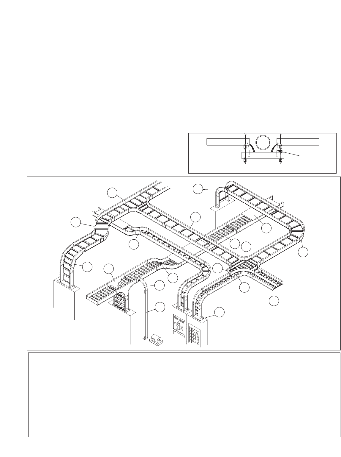
support. Although the use of cable tray fittings is not
mandatory, it is often desirable to use them when
possible to improve the appearance of the
installation.
392.5. Construction Specifications. (F)
Nonmetallic Cable Tray.
This type of cable tray is usually made of
Fiberglass Reinforced Plastic (FRP). Applications for
FRP cable tray systems include some corrosive
atmospheres and where non-conductive material is
required. B-Line fiberglass cable tray systems are
manufactured from glass fiber reinforced plastic
shapes that meet ASTM flammability and self-
extinguishing requirements. A surface veil is applied
during pultrusion to ensure a resin rich surface and
increase ultraviolet resistance, however, for extended
exposure to direct sunlight, additional measures,
such as painting the tray, are sometimes employed
to insure the longevity of the product. Ambient
temperature is also a design consideration when
FRP cable tray is used. An ambient temperature of
100°F will decrease the loading capacity of poltester
resin fiberglass cable tray by 10%.
392.6. Installation. (A) Complete System.
This section states that cable tray systems can
have mechanically discontinuous segments, and that
the mechanically discontinuous segment cannot be
greater than 6 feet. A bonding jumper sized per
Section 250.102 is necessary to connect across any
discontinuous segment. The bonding of the system
should be in compliance with Section 250.96.
21
Cable Tray Manual Cooper B-Line, Inc
Nomenclature
1. Ladder Type Cable Tray 10. 30° Vertical Inside Bend, Ladder Type Tray
2. Ventilated Trough Type Cable Tray 11. Vertical Bend Segment (VBS)
3. Splice Plate 12. Vertical Tee Down, Ventilated Trough Type Tray
4. 90° Horizontal Bend, Ladder Type Tray 13. Left Hand Reducer, Ladder Type Tray
5. 45° Horizontal Bend, Ladder Type Tray 14. Frame Type Box Connector
6. Horizontal Tee, Ladder Type Tray 15. Barrier Strip Straight Section
7. Horizontal Cross, Ladder Type Tray 16. Solid Flanged Tray Cover
8. 90° Vertical Outside Bend, Ladder Type Tray 17. Cable Channel Straight Section, Ventilated
9. 45° Vertical Outside Bend, Ventilated Type Tray 18. Cable Channel, 90° Vertical Outside Bend
1
2
3
4
6
7
8
10
11 12 13
14
15
16
17
18
Typical Cable
Tray Layout
5
9
Cable Tray Elevation Change Without Fittings
Bonding
Jumper
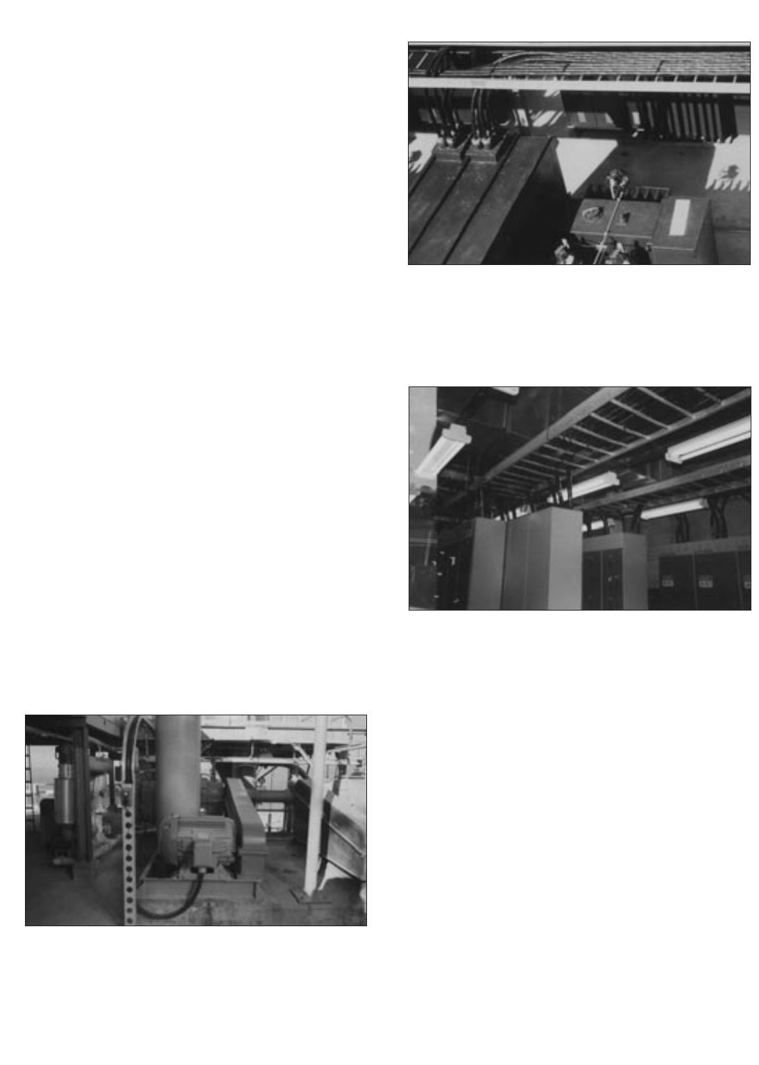
There are some designers, engineers, and
inspectors that do not think that cable tray is a
mechanical support system just as strut is a
mechanical support system. Cable tray is not a
raceway in the NEC®but some designers, engineers,
and inspectors attempt to apply the requirements for
raceway wiring systems to cable tray wiring systems
even when they are not applicable. Cable tray wiring
systems have been used by American industry for
over 35 years with outstanding safety and continuity
of service records. The safety service record of cable
tray wiring systems in industrial facilities has been
significantly better than those of conduit wiring
systems. There have been industrial fires and
explosions that have occurred as a direct result of the
wiring system being a conduit wiring system. In these
cases, cable tray wiring systems would not have
provided the fires and explosions that the conduit
systems did by providing as explosion gas flow path
to the ignition source even though the conduit
systems contained seals.
The most significant part of this section is that the
metallic cable tray system must have electrical
continuity over its entire length and that the support
for the cables must be maintained. These
requirements can be adequately met even though
there will be installation conditions where the cable
tray is mechanically discontinuous, such as at a
firewall penetration, at an expansion gap in a long
straight cable tray run, where there is a change in
elevation of a few feet between two horizontal cable
tray sections of the same run, or where the cables
drop from an overhead cable tray to enter
equipment. In all these cases, adequate bonding
jumpers must be used to bridge the mechanical
discontinuity.
Control Cable Entering Pushbutton and
Power Cable Entering Motor Terminal Box
from 6 Inch Channel Cable Tray System
(Bottom entries provide drip loops to prevent moisture
flow into enclosures.)
Cables Exiting 480 Volt Outdoor
Switchgear and Entering Cable Tray System
(Cable fittings with clamping glands are required to prevent
moisture flow into equipment due to the cable's overhead
entry into the switchgear enclosure).
Cables Entering and Exiting Motor Control
Centers from Cable Tray Systems.
392.6. Installation. (B) Completed Before
Installation.
This means that the final cable tray system must
be in place before the cables are installed. It does
not mean that the cable tray must be 100%
mechanically continuous. The electrical bonding of
the metallic cable tray system must be complete
before any of the circuits in the cable tray system
are energized whether the cable tray system is being
utilized as the equipment grounding conductor in
qualifying installations or if the bonding is being
done to satisfy the requirements of Section 250.96.
22
Cooper B-Line, Inc Cable Tray Manual
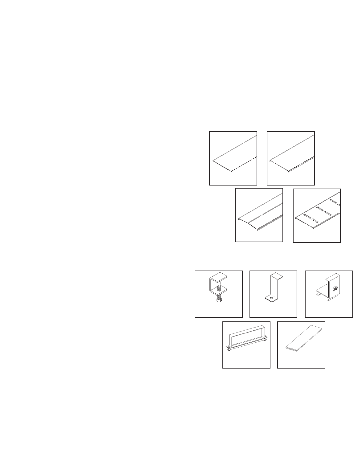
392.6. Installation. (C) Supports.
The intent of this section is to ensure that the
conductor insulation and cable jackets will not be
damaged due to stress caused by improper support.
Multiconductor 600 volt Type TC cables and 300
volt Type PLTC cables exhibit a high degree of
damage resistance when exposed to mechanical
abuse at normal temperatures.
During an inspection of industrial installations by
the 1973 NEC®Technical Subcommittee on Cable
Tray, a test setup was constructed of an 18 inch
wide Class 20C aluminum cable tray supported
three feet above ground level containing several
sizes of multiconductor cables. This installation was
continuously struck in the same area with eight
pound sledge hammers until the cable tray was
severely distorted, the cables however, exhibited
only cosmetic damage. When these cables were
tested electrically, they checked out as new tray
cable. Since that time, significant improvements
have been made in cable jacket and conductor
insulation materials so that the cables available today
are of better quality than the 1973 test cables.
Although tray cables are capable of taking a great
deal of abuse without any problems, cable tray
installations must be designed by taking appropriate
measures to ensure that the tray cables will not be
subjected to mechanical damage.
392.6. Installation. (D) Covers.
Cable tray covers provide protection for cables
where cable trays are subject to mechanical damage.
The most serious hazard to cable in cable trays is
when the cables are exposed to significant amounts
of hot metal spatter during construction or
maintenance from torch cutting of metal and
welding activities. For these exposure areas, the
cable tray should be temporarily covered with
plywood sheets. If such exposure is to be a frequent
occurrence, cable tray covers should be installed in
the potential exposure areas. Where cable trays
contain power and lighting conductors, raised or
ventilated covers are preferable to solid covers since
the raised or ventilated covers allow the cable heat
to be vented from the cable tray.
When covers are installed outdoors, they should
be attached to the cable trays with heavy duty wrap
around clamps instead of standard duty clips. During
high winds, the light duty clips are not capable of
restraining the covers. Outdoor cover installations
should be overlapped at expansion joint locations to
eliminate cover buckling. Covers which fly off the
cable tray create a serious hazard to personnel, as
was the case at a Texas gulf coast chemical plant
where operators would not leave their control room
because hurricane force winds had stripped many
light gauge stainless steel covers off a large cable
tray system. These sharp edged metal covers were
flying though the air all during the high wind period,
posing a serious threat to the worker's safety.
Types of Cable Tray Covers.
Aluminum Cable Tray Cover Accessories -
Equivalent Items are available for Steel Cable Trays.
23
Cable Tray Manual Cooper B-Line, Inc
Standard
Cover Clamp
Combination Cover
& Hold Down Clamp
Heavy Duty
Cover Clamp Cover Joint Strip
Raised
Cover Clamp
Solid Non-Flanged Solid Flanged
Ventilated Flanged
Peaked Flanged
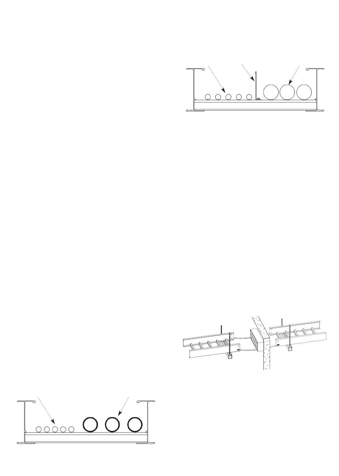
392.6. Installation. (E) Multiconductor
Cables Rated 600 Volts or Less.
Cables containing 300 or 600 volt insulated
conductors may be installed intermingled in the
same cable tray which is different from the
requirements for raceways. This is a reasonable
arrangement because a person may safely touch a
300 or 600 volt cable which is in good condition, so
having the cables come into contact with each other
is not a problem either. Many cable tray users
separate the instrumentation cables from the power
and control cables by installing them in separate
cable trays or by installing barriers in the cable trays.
Often, because of the volume of the instrumentation
cable, using separate cable trays is the most
desirable installation practice.
Numerous cable tray systems have been installed
where the instrumentation cables and branch circuit
cables are installed in the same cable trays with and
without barriers with excellent performance and
reliability. Most problems that occur involving
instrumentation circuits are due to improper
grounding practices. For analog and digital
instrumentation circuits, good quality twisted pair
Type ITC and Type PLTC cables with a cable shield
and a shield drain wire should be used. Do not
purchase this type of cable on price alone, it should
be purchased because of it's high quality. Engineers
specifying cables should be knowledgeable of the
cable's technical details in order to design systems
which will provide trouble free operation.
392.6. Installation. (F) Cables Over 600
Volts.
Cables with insulation rated 600 volts or less may
be installed with cables rated over 600 volts if either
of the following provisions are met.
No. 1: Where the cables over 600 volts are
Type MC.
No. 2: Where separated with a fixed solid
barrier of a material compatible with the cable
tray.
392.6. Installation. (G) Through Partitions
and Walls.
Whether penetrating fire rated walls with tray cable
only or cable tray and tray cable, the designer should
review with the local building inspector the method
he proposes to use to maintain the fire rating
integrity of the wall at the penetration. Many
methods for sealing fire wall penetrations are
available, including bag or pillow, caulk,
cementitious, foam, putty and mechanical barrier
systems.
Many designers prefer to run only the tray cable
through fire rated walls. Sealing around the cables is
easier than sealing around the cables and the cable
tray. Also, should the cable tray or its supports
become damaged, the tray will not exert forces
which could damage the wall or the penetration.
392.6. Installation. (H) Exposed and
Accessible.
Article 100 - Definitions.
Exposed: (as applied to wiring methods)
on or attached to the surface or behind
panels designed to allow access.
24
Cooper B-Line, Inc Cable Tray Manual
300 & 600
Volt Cables Fixed Solid Barrier
Comparable Material Cables Rated
Over 600 Volts
NO. 2
300 & 600
Volt Cables Cables Rated Over
600 Volts Are Type MC
NO. 1

Accessible: (As applied to wiring methods)
Capable of being removed or exposed
without damaging the building structure or
finish, or not permanently closed in by the
structure or finish of the building.
Reprinted with permission from NFPA 70-1999, the National Electrical Code®,
Copyright© 1998, National Fire Protection Association, Quincy, MA 02269. This reprinted
material is not the complete and official position of the National Fire Protection Association,
on the referenced subject which is represented only by the standard in its entirety.
392.6. Installation. (I) Adequate Access.
Cable tray wiring systems should be designed and
installed with adequate room around the cable tray
to allow for the set up of cable pulling equipment.
Also, space around the cable tray provides easy
access for installation of additional cables or the
removal of surplus cables. Where cable trays are
mounted one above the other, a good rule to follow
is to allow 12 to 18 inches between the underside
and the top of adjacent cable trays or between the
structure's ceiling and the top of the cable tray.
392.6. Installation. (J) Conduits and
Cables Supported from Cable Tray.
For the 1996 NEC®, a significant change was
made in this section. The installations covered in
this section may now only be made in qualifying
industrial facilities.
In Section 392.6(J) of the 1993 NEC®, cable tray
installations that supplied support for conduits were
not restricted to qualifying industrial facilities. The
1996 NEC®, Section 392.6(J) text restricts the use
of such installations even though there is no
documented history of problems in non-industrial
installations.
As a result of the change in this section, identical
functional installations in non-qualifying installations
(commercial and industrial) and qualifying industrial
installations have different physical requirements. In
a qualifying industrial installation, a conduit
terminated on a cable tray may be supported from
the cable tray. In a commercial or non-qualifying
industrial installation, the conduit that is terminated
on the cable tray must be securely fastened to a
support that is within 3 feet of the cable tray or
securely fastened to a support that is within 5 feet of
the cable tray where structural members don’t
readily permit a secure fastening within 3 feet. The
conduit of the non-qualifying installation still needs
to be bonded to the cable tray. A fitting may be used
for this bonding even though it will not count as a
mechanical support.
Over 99 percent of the conduits supported on
cable trays are the result of conduits being
terminated on the cable tray side rails [See Section
392.8(C)]. For over 40 years, it has been common
practice to house the cables exiting the cable tray in
conduits or cable channel where the distance from
the cable tray system to the cable terminations
requires the cable be supported. Several
manufacturers supply UL approved cable tray to
conduit clamps such as the B-Line 9ZN-1158.
In addition to conduit and cables being supported
from cable tray; industrial companies have been
mounting instrumentation devices, push buttons, etc.
on cable tray and cable channel for over 40 years.
This section once lead some to believe that only
conduit or cables may be supported from cable trays
which is not correct as cable tray is a mechanical
support just as strut is a mechanical support.
Because of this, the wording in Section 392.6(J) of
the 2002 NEC®was changed. Instead of allowing
only cable and conduit to be supported from cable
tray, the code now states that raceways, cables,
boxes and conduit bodies are now permitted to
be supported from the cable tray. Where boxes or
conduit bodies are attached to the bottom or side of
the cable tray, they must be fastened and supported
in accordance with Section 314.23.
25
Cable Tray Manual Cooper B-Line, Inc

26
Cooper B-Line, Inc Cable Tray Manual
UL Listed Conduit To
Cable Tray Clamp
See NEC®Table 344.30(B)(2) To Obtain The
Support Requirements For Other Conduit Sizes.
Conduit Terminated On And Supported By The Cable Tray Side Rail.
Installation For Qualifying Industrial Facilities As Per 392.6(J).
16 Feet
2 Inch Rigid Metal Conduit
Position Of The First
Conduit Support
From The Cable Tray
(Conduit Must Be
Securely Fastened To
The Support)
Conduit Bushing
Cable Tray
Side Rail
Cable Tray
UL Listed Conduit To
Cable Tray Clamp
See Section 344.30
Conduit Terminated On The Cable Tray Side Rail.
Installation For Commercial And Non-Qualifying Industrial Facilities As Per 392.6(J).
3 Feet or 5 Feet
Any Size Of Rigid Metal Conduit
Position Of The First
Conduit Support
From The Cable Tray
(Conduit Must Be
Securely Fastened To
The Support)
Conduit Bushing
Cable Tray
Side Rail
Cable Tray
392.7. Grounding. (A) Metallic Cable
Trays.
All metallic cable trays shall be grounded as
required in Article 250 regardless of whether or not
the cable tray is being used as an equipment
grounding conductor (EGC).
The EGC is the most important conductor in an
electrical system as its function is electrical safety.
There are three wiring options for providing an
EGC in a cable tray wiring system: (1) An EGC
conductor in or on the cable tray. (2) Each
multiconductor cable with its individual EGC
conductor. (3) The cable tray itself is used as the
EGC in qualifying facilities.
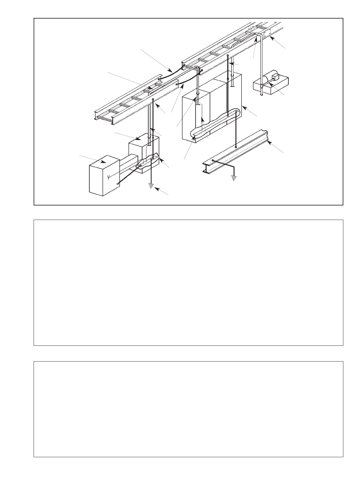
27
Cable Tray Manual Cooper B-Line, Inc
Ground Bus
Bonded To
Enclosure
EGC
EGC In
Cable
Discontinuous Joints
Require Bonding
For Qualifying Facilities
EGCs in the Cables or
EGC Cables Are Not
Required If Rating Of The
Feeder Overcurrent Device
Permits Using The Tray
For the EGC
Bonding Jumper Not
Required For Rigidly
Bolted Joints
Conduit
Three Phase
Motor Installation
Building Steel
Lightning
Protection
Grounding
Bond
Switchgear
Bond
System Ground
Transformer
(Solidly
Grounded
Secondary)
Motor Control Center
Correct Bonding Practices To Assure That The
Cable Tray System Is Properly Grounded
If an EGC cable is installed in or on a cable tray, it should be bonded to each or alternate cable
tray sections via grounding clamps (this is not required by the NEC®but it is a desirable practice). In
addition to providing an electrical connection between the cable tray sections and the EGC, the
grounding clamp mechanically anchors the EGC to the cable tray so that under fault current
conditions the magnetic forces do not throw the EGC out of the cable tray.
A bare copper equipment grounding conductor should not be placed in an aluminum cable tray
due to the potential for electrolytic corrosion of the aluminum cable tray in a moist environment.
For such installations, it is best to use an insulated conductor and to remove the insulation where
bonding connections are made to the cable tray, raceways, equipment enclosures, etc. with tin or
zinc plated connectors.
See Table 250.122 on page 51
for the minimum size EGC for
grounding raceway and equipment.

28
Cooper B-Line, Inc Cable Tray Manual
392.7. Grounding. (B) Steel or Aluminum
Cable Tray Systems. (1) & (2)
Reprinted with permission from NFPA 70-1999, the National Electrical Code®,
Copyright© 1998, National Fire Protection Association, Quincy, MA 02269. This reprinted
material is not the complete and official position of the National Fire Protection Association,
on the referenced subject which is represented only by the standard in its entirety.
Table 392.7(B) "Metal Area Requirements for
Cable Trays used as Equipment Grounding
Conductors" shows the minimum cross-sectional
area of cable tray side rails (total of both side rails)
required for the cable tray to be used as the
Equipment Grounding Conductor (EGC) for a
specific Fuse Rating, Circuit Breaker Ampere Trip
Rating or Circuit Breaker Ground Fault Protective
Relay Trip Setting. These are the actual trip settings
for the circuit breakers and not the maximum
permissible trip settings which in many cases are the
same as the circuit breaker frame size. If the
maximum ampere rating of the cable tray is not
sufficient for the protective device to be used, the
cable tray cannot be used as the EGC and a
separate EGC must be included within each cable
assembly or a separate EGC has to be installed in or
attached to the cable tray. [See also Section 250-
120 for additional information]
The subject of using cable tray for equipment
grounding conductors was thoroughly investigated
by the 1973 NEC®Technical Subcommittee on
Cable Tray. Many calculations were made and a
number of tests were performed by Monsanto
Company Engineers at the Bussman High Current
Laboratory. The test setup to verify the capability of
cable tray to be used as the EGC is shown in Figure
1 on page 29. The test amperes available were
forced through one cable tray side rail which had
three splice connections in series. No conductive
joint compound was used at the connections and the
bolts were wrench tight. Copper jumper cables were
used from the current source to the cable tray. The
cable tray was NEMA Class 12B. The test results
are shown on Page 45 (Appendix Sheet 1), Table I
for aluminum and Table II for steel cable tray.
One of the most interesting results of the tests was
for an aluminum cable tray with a corroded joint and
only two nylon bolts. 34,600 amperes for 14 cycles
produced only a 34° C temperature rise at the splice
plate area. If the protective devices work properly,
the temperature rises recorded at the cable tray
splices during these tests would not be sufficient to
damage the cables in the cable tray. Also note that
in these tests only one side rail was used, but in a
regular installation, both side rails would conduct
fault current and the temperature rise at the splice
plate areas would be even lower.
When the cable tray is used as the EGC,
consideration has to be given to the conduit or
ventilated channel cable tray connections to the
cable tray so that the electrical grounding continuity
is maintained from the cable tray to the equipment
utilizing the electricity. Conduit connections to the
cable tray were also tested. At that time, no
commercial fittings for connecting conduit to cable
tray were available, so right angle beam clamps
were used with very good results. There are now UL
Listed fittings for connecting and bonding conduit to
cable tray. This test setup and results are shown on
page 46 (Appendix Sheet 2).
Table 392.7(B).
Metal Area Requirements for Cable Trays
Used as Equipment Grounding Conductors
Maximum Fuse Ampere Rating,
Circuit Breaker Ampere Trip Minimum Cross-Sectional Area
Setting, or Circuit Breaker of Metal* In Square Inches
Protective Relay Ampere Trip
Setting for Ground-Fault
Protection of Any Cable Circuit Steel Aluminum
In the Cable Tray System Cable Trays Cable Trays
60 0.20 0.20
100 0.40 0.20
200 0.70 0.20
400 1.00 0.40
600 1.50** 0.40
1000 --- 0.60
1200 --- 1.00
1600 --- 1.50
2000 --- 2.00**
For SI units: one square inch = 645 square millimeters.
*Total cross-sectional area of both side rails for ladder or
trough cable trays; or the minimum cross-sectional area of
metal in channel cable trays or cable trays of one-piece
construction.
**Steel cable trays shall not be used as equipment grounding
conductors for circuits with ground-fault protection above 600
amperes. Aluminum cable trays shall not be used as equipment
grounding conductors for circuits with ground-fault protection
above 2000 amperes.
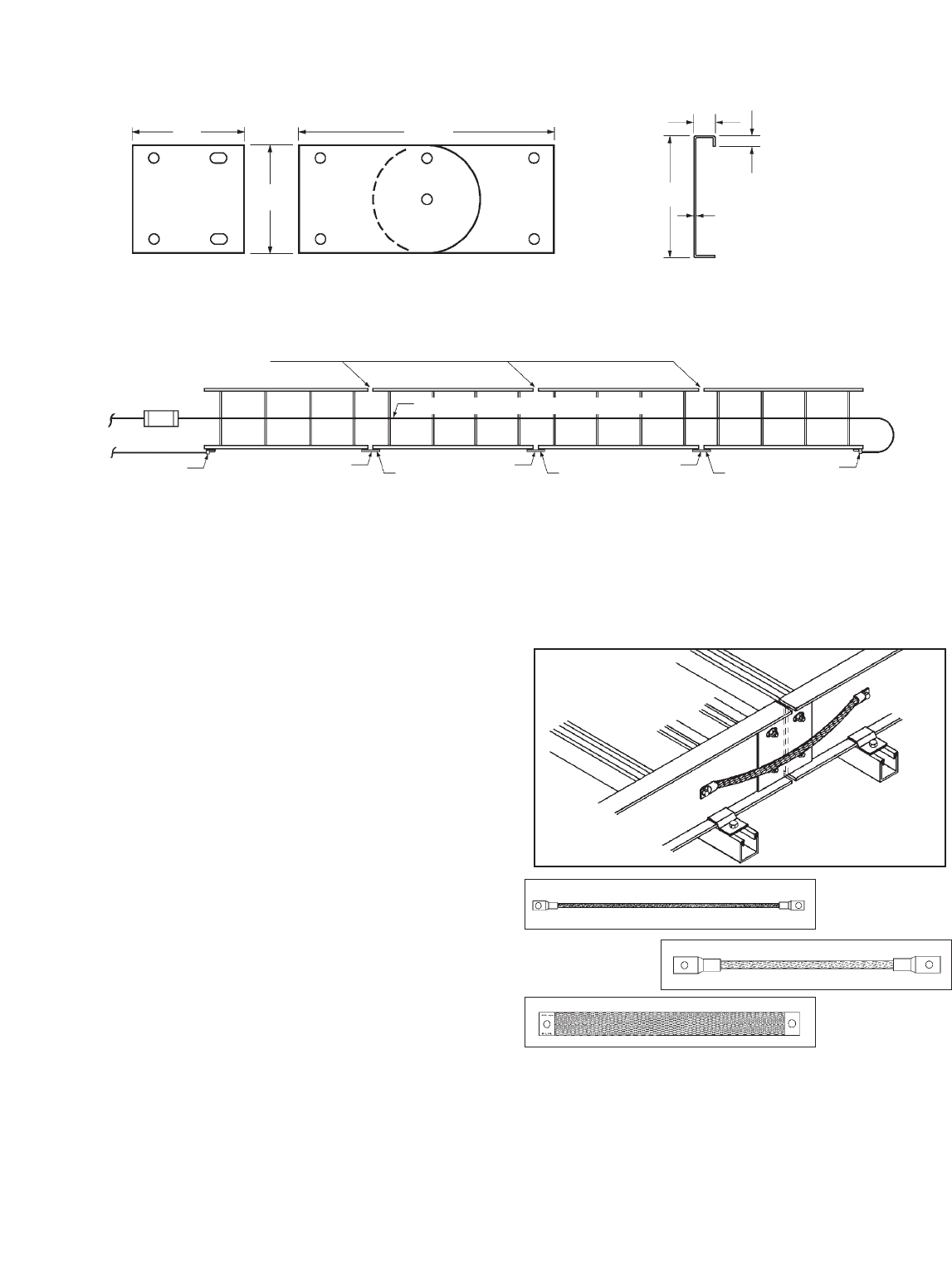
29
Cable Tray Manual Cooper B-Line, Inc
Material Thickness: 0.125" Aluminum or 14 Gauge Steel Cross Section Area,
2 Rails:
Aluminum - 1.00 sq. in.
Steel - 0.76 sq. in.
13/16"
3/8"
0.080" Aluminum or
14 Gauge Steel
3/8" Bolting Hardware
Cross Section Cable
Tray Side Rail
Adjustable Vertical
Rigid
Cable Tray Connectors
41/2"
91/2"
4"
4"
Figure 1
(See Page 45 Appendix Sheet 1)
Temperature Rise Test
C1
T T T
C2 C3
Current Source
500 kcmil copper, Type RH Insulation
Insulated Joints
Cable Lug
Fuse (if used)
Cable Lug
T - Temperature Measurement at each Tray Connection C1,
C2, & C3 - Cable Tray Connectors or Bonding Jumpers
392.7. Grounding. (B) Steel or Aluminum
Cable Tray Systems. (3) & (4)
For a cable tray to be used as an EGC the
manufacturer must provide a label showing the
cross-sectional area available. This also holds true
for some mechanically constructed cable tray
systems such as Redi-Rail®. Redi-Rail has been
tested and UL Classified as an EGC. B-Line's label is
shown at the top of page 30.
The cable tray system must be electrically
continuous whether or not it is going to serve as the
EGC. At certain locations (expansion joints,
discontinuities, most horizontal adjustable splice
plates, etc.), bonding jumpers will be required.
Section 250.96. Bonding Other Enclosures states
that cable tray shall be effectively bonded where
necessary to assure electrical continuity and to
provide the capacity to conduct safely any fault
current likely to be imposed on them (also see Sections
250.92(A)(1) & 250.118(12)).
It is not necessary to install bonding jumpers at
standard splice plate connections. The splice
connection is UL classified as an EGC component
of the cable tray system.
NOTE: The NEC®only recognizes aluminum and
steel cable trays as EGC’s. As with all metallic cable
trays, stainless steel cable trays must be bonded
according to NEC® guidelines. Fiberglass cable
trays do not require bonding jumpers since fiberglass
is non-conductive.
99-N1
600 amps max.
99-40
1600 amps max.
99-1620
2000 amps max.

30
Cooper B-Line, Inc Cable Tray Manual
Cable Tray Label
392.8. Cable Installation. (A) Cable
Splices.
There is no safety problem due to cable splices
being made in cable trays if quality splicing kits are
used, provided that the splice kits do not project
above the siderails and that they are accessible. A
box or fitting is not required for a cable splice in a
cable tray
392.8. Cable Installation. (B) Fastened
Securely.
There is no safety or technical reason to tie down
multiconductor cables in horizontal cable tray runs
unless the cable spacing needs to be maintained or
the cables need to be confined to a specific location
in the cable tray. In non-horizontal cable tray runs,
small multiconductor cables should be tied down at
3 or 4 foot intervals and larger (1 inch diameter and
above) Type MC and Type TC multiconductor
cables should be tied down at 6 foot intervals. If
used outdoors, plastic ties should be sunlight,
ultraviolet (UV), resistant and be made of a material
that is compatible with the industrial environment.
Installed outdoors, white nylon plastic ties without a
UV resistant additive will last 8 to 14 months before
breaking. Also available for these applications are
stainless steel ties and P-clamps.
(P-Clamp shown installed on industrial aluminum rung)
For single conductor cables installed in cable tray
in a single layer, each single conductor cable should
be tied to the cable tray at 6 foot intervals. Where a
circuit group of single conductors (Phase A, Phase
B, Phase C, and a Neutral if used) are bound
together with ties, the ties should be at three or four
foot intervals. In horizontal cable tray runs, the
circuit groups with ties do not have to be tied to the
cable tray. Where ties are used, they should be
made from high strength UV resistant plastic or
stainless steel. The high amperages flowing under
fault conditions in the 1/0 and larger cables
produce strong magnetic fields which result in the
conductors repelling each other until the circuit
protective device de-energizes the circuit. Under
such conditions, the cables might be forced out of
the cable tray. This happened at a northern Florida
textile plant where several hundred feet of Type MV
single conductor cable was forced out of a cable tray
run by an electrical fault because the cables were not
tied down properly.
WARNING!
Use Only As A Mechanical Support For Cables, Tubing and Raceways.
Do Not Use As A Walkway, Ladder,
Or Support For Personnel.
VENTILATED
09/05/2002
816 LIONS DRIVE
TROY, IL 62294
(618) 667-6779
Catalog Number: 24A09-12-144 STR SECTION
(and description)
Shipping Ticket: 260203 00 001
Mark Number: 78101115400
Purchase Order: D798981
Minimum Area: 1.000 SQ. IN.
Load Class: D1 179 KG/M 3 METER SPAN
REFERENCE FILE # LR360266
This product is classified by Underwriters Laboratories, Inc. as to
its suitability as an equipment grounding conductor only. 556E
30781011154005
1 of 1
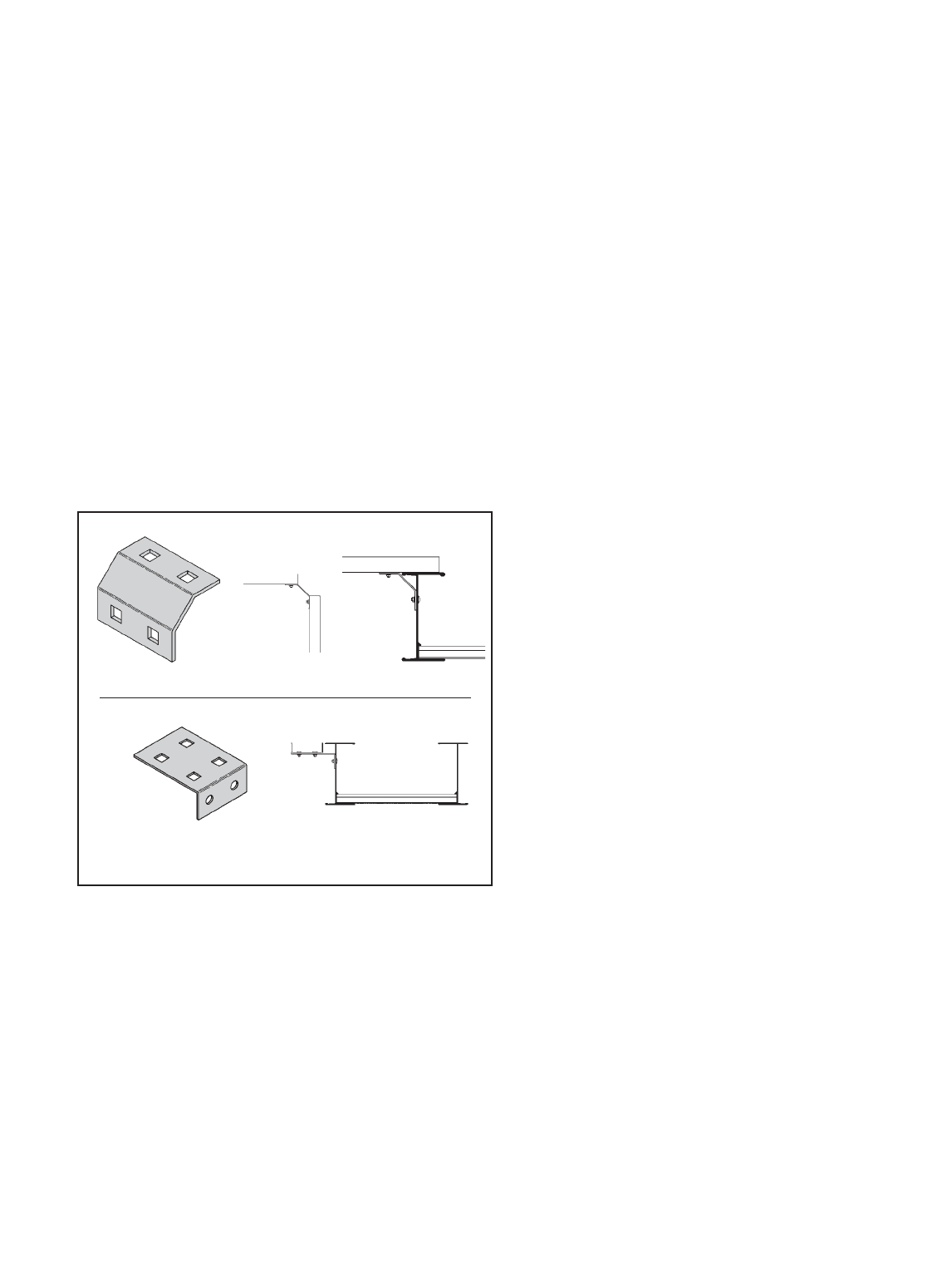
392.8. Cable installation. (C) Bushed
Conduit and Tubing.
For most installations, using a conduit to cable tray
clamp for terminating conduit on cable tray is the
best method. Where a cable enters a conduit from
the cable tray, the conduit must have a bushing to
protect the cable jacket from mechanical damage; a
box is not required [See Section 300.15(C). Boxes,
Conduit Bodies, or Fittings - Where Required. Where
cables enter or exit from conduit or tubing that is
used to provide cable support or protection against
physical damage. A fitting shall be provided on the
end(s) of the conduit or tubing to protect the wires or
cables from abrasion.]. There are some special
installations where the use of conduit knockouts in
the cable tray side rail for terminating conduit is
appropriate. This would not be a good standard
practice because it is costly and labor intensive, and
if randomly used may result in damaging and
lowering the strength of the cable tray.
392.8. Cable Installation. (D) Connected
in Parallel.
Section 310.4. Conductors in Parallel. States the
following:
The paralleled conductors in each phase, neutral
or grounded conductor shall:
(1) Be the same length.
(2) Have the same conductor material.
(3) Be the same size in circular mil area.
(4) Have the same insulation type.
(5) Be terminated in the same manner.
Where run in separate raceways or cables, the
raceways or cables shall have the same physical
characteristics. Conductors of one phase, neutral, or
grounded circuit shall not be required to have the
same physical characteristics as those of another
phase, neutral, or grounded circuit conductor to
achieve balance.
A difference between parallel conductors in
raceways and those in cable trays is that the
conductors in the cable tray are not derated unless
there are more than three current carrying
conductors in a cable assembly [as per Exception
No.2 of Section 310.15(B)(2)(a) and Section
392.11(A)(1)]. Where the single conductor cables
are bundled together as per Section 392.8(D) and if
there are neutrals that are carrying currents due to
the type of load involved (harmonic currents) it may
be prudent to derate the bundled single conductor
cables .
To maintain the minimum distance between
conductors, the single conductor cables should be
securely bound in circuit groups every three or four
feet using high strength plastic or stainless steel ties.
These circuit groups provide the lowest possible
circuit reactance which is a factor in determining the
current balance among various circuit groups.
For installations that involve phase conductors of
three conductor or single conductor cables installed
in parallel, cable tray installations have conductor
cost savings advantages over conduit wiring systems.
This is because the conductors required for a cable
tray wiring system are often a smaller size than
those required for a conduit wiring system for the
same circuit. No paralleled conductor ampacity
adjustment is required for single conductor or three
conductor cables in cable trays [See NEC®Section
392.11(A)].
There were changes in the 1993 NEC®and 1996
NEC®for installations where an equipment
grounding conductor is included in a multiconductor
cable: the equipment grounding conductor must be
fully rated per Section 250.122. If multiconductor
cables with internal equipment grounding
conductors are paralleled, each multiconductor cable
must have a fully rated equipment grounding
conductor.
Section 250.122 now prohibits the use of standard
three conductor cables with standard size EGCs when
they are installed in parallel and the EGCs are
paralleled. There have been no safety or technical
31
Cable Tray Manual Cooper B-Line, Inc
Cable Channel Branch Circuit
Reprinted with permission from NFPA 70-1999, the National Electrical Code®, Copyright© 1998, National Fire
Protection Association, Quincy, MA 02269. This reprinted material is not the complete and official position of the National
Fire Protection Association, on the referenced subject which is represented only by the standard in its entirety.
Channel to Tray
Channel to
Channel

problems due to operating standard three conductor
cables with standard sized EGCs in parallel. This has
been a standard industrial practice for over 40 years
with large numbers of such installations in service.
This change was made without any safety or
technical facts to justify this change.
To comply with Section 250.122, Three options
are available: 1. Order special cables with increased
sized EGCs which increases the cost and the
delivery time. 2. Use three conductor cables without
EGCs and install a single conductor EGC in the
cable tray or use the cable tray as the EGC in
qualifying installations. 3. Use standard cables but
don’t utilize their EGCs, use a single conductor EGC
or the cable tray as the EGC in qualifying
installations.
Should industry be required to have special cables
fabricated for such installations when there have
been absolutely no safety problems for over 40
years? Each designer and engineer must make his
own decision on this subject. If the installations are
properly designed, quality materials are used, and
quality workmanship is obtained, there is no safety
reason for not following the past proven practice of
paralleling the EGCs of standard three conductor
cable.
392.8. Cable Installation. (E) Single
Conductors.
This section states that single conductors in ladder
or ventilated trough cable tray that are Nos. 1/0
through 4/0, must be installed in a single layer.
In addition to the fill information that is in Section
392.10(A)(4), an exception was added which allows
the cables in a circuit group to be bound together
rather than have the cables installed in a flat layer.
The installation practice in the exception is desirable
to help balance the reactance’s in the circuit group.
This reduces the magnitudes of voltage unbalance in
three phase circuits.
Where ladder or ventilated trough cable trays
contain multiconductor power or lighting cables, or
any mixture of multiconductor power, lighting,
control, or signal cables, the maximum number of
cables that can be installed in a cable tray are limited
to the Table 392.9 allowable fill areas. The cable
tray fill areas are related to the cable ampacities.
Overfill of the cable tray with the conductors
operating at their maximum ampacities will result in
cable heat dissipation problems with the possibility
of conductor insulation and jacket damage.
392.9. Number of Multiconductor Cables.
Rated 2000 Volts or less, in Cable Trays.
(A) Any Mixture of Cables. (1) 4/0 or
Larger Cables
The ladder or ventilated trough cable tray must
have an inside usable width equal to or greater than
the sum of the diameters (Sd) of the cables to be
installed in it. For an example of the procedure to
use in selecting a cable tray width for the type of
cable covered in this section see page 47 (Appendix
Sheet 3), [Example 392.9(A)(1)].
Increasing the cable tray side rail depth increases
the strength of the cable tray but the greater side rail
depth does not permit an increase in cable fill area
for power or lighting cables or combinations of
power, lighting, control and signal cables. The
maximum allowable fill area for all cable tray with a
3 inch or greater loading depth side rail is limited to
the 38.9 percent fill area for a 3 inch loading depth
32
Cooper B-Line, Inc Cable Tray Manual
Compatibility Of Cable Tray Types And
Cable Trays Based On The NEC®
3", 4", & 6" Wide Solid or
Ventilated Channel Cable Tray
Solid Bottom Cable Tray
Ventilated Trough Cable Tray
Ladder Cable Tray
X - Indicates the Installations Allowed by Article 392
* - For cables rated up to 2000 volts.
** - For cables rated above 2000 volts.
*** - For 1/0 - 4/0 AWG single conductor cables
installed in ladder cable tray, maximum rung
spacing is 9 inches.
XXXX
* * *
X X X
X X X
X X X
Multiconductor Cables
300 & 600 Volt *
Single Conductor
Cables - 600 Volt *
Type MV Multiconductor
Cables **
Type MV Single Conductor
Cables **

33
Cable Tray Manual Cooper B-Line, Inc
side rail (Example: 3 inches x 6 inches inside cable
tray width x 0.389 = 7.0 square inch fill area. This
is the first value in Column 1 of Table 392.9. All
succeeding values for larger cable tray widths are
identically calculated).
392.9. Number of Multiconductor Cables.
Rated 2000 Volts or less, in Cable Trays.
(A) Any Mixture of Cable. (2) Cables
Smaller Than 4/0
The allowable fill areas for the different ladder or
ventilated trough cable tray widths are indicated in
square inches in Column 1 of Table 392.9. The
total sum of the cross-sectional areas of all the
cables to be installed in the cable tray must be equal
to or less than the cable tray allowable fill area. For
an example of the procedure to use in selecting a
cable tray width for the type of cable covered in this
section see page 48 (Appendix Sheet 4), [Example
392.9(A)(2)].
392.9. Number of Multiconductor Cables.
Rated 2000 Volts or less, in Cable Trays.
(A) Any Mixture of Cables. (3) 4/0 or
Larger Cables Installed With Cables
Smaller Than 4/0
The ladder or ventilated trough cable tray needs to
be divided into two zones (a barrier or divider is not
required but one can be used if desired) so that the
No. 4/0 and larger cables have a dedicated zone as
they are to be placed in a single layer.
The formula for this type of installation is shown
in Column 2 of Table 392.9. This formula is a trial
and error method of selecting a cable tray of the
proper width. A direct method for determining the
cable tray width is available by figuring the cable tray
widths that are required for each of the cable
combinations and then adding these widths together
to select the proper cable tray width. [Sd (sum of
the diameters of the No. 4/0 and larger cables)] +
[Sum of Total Cross Sectional Area of all Cables No.
3/0 and Smaller) x (6 inches/7 square inches)] =
The Minimum Width of Cable Tray Required. For an
example of the procedure to use in selecting a cable
tray width for the type of cable covered in this
section, see page 49, (Appendix Sheet 5), [EXAMPLE
392.9(A)(3)].
392.9. Number of Multiconductor Cables.
Rated 2000 Volts or less, in Cable Trays.
(B) Multiconductor Control and/or Signal
Cables Only.
A ladder or ventilated trough cable tray, having a
loading depth of 6 inches or less containing only
control and/or signal cables, may have 50 percent
of its cross-sectional area filled with cable. If the
cable tray has a loading depth in excess of 6 inches,
that figure cannot be used in calculating the
allowable fill area as a 6 inch depth is the maximum
value that can be used for the cross-sectional area
calculation. For an example of the procedure to use
in selecting a cable tray width for the type of cable
covered in this section, see page 50 (Appendix Sheet
6),[Example 392.9 (B)].
392.9. Number of Multiconductor Cables,
Rated 2000 Volts, Nominal, or Less, in
Cable Trays. (C) Solid Bottom Cable Trays
Containing Any Mixture.
For solid bottom cable tray, the allowable cable fill
area is reduced to approximately 30 percent as
indicated by the values in Columns 3 and 4 of Table
392.9. The first value in Column 3 was obtained as
follows: 3 in. loading depth x 6 in. inside width x
0.305 = 5.5 square inches. The other values in
Column 3 were obtained in a like manner. The Sd
term in Column 4 has a multiplier of 1 vs. the
multiplier of 1.2 for Column 2.
392.9. Number of Multiconductor Cables,
Rated 2000 Volts, Nominal, or Less, in
Cable Trays. (C) Solid Bottom Cable
Trays Containing any Mixture. (1) 4/0 or
Larger Cables
The procedure used in selecting a cable tray width
for the type of cable covered in this section is similar
to that shown on Appendix Sheet 3 page 47, but
only 90 percent of the cable tray width can be used.
34
Cooper B-Line, Inc Cable Tray Manual
392.9. Number of Multiconductor Cables,
Rated 2000 Volts, Nominal, or Less, in
Cable Trays. (C) Solid Bottom Cable
Trays Containing Any Mixture. (2) Cables
Smaller Than 4/0
The procedure used in selecting a cable tray width
for the type of cable covered in this section is similar
to that shown on Appendix Sheet 4 page 48. The
maximum allowable cable fill area is in Column 3 of
Table 392.9.
392.9. Number of Multiconductor Cables,
Rated 2000 Volts, Nominal, or Less, in
Cable Trays. (C) Solid Bottom Cable
Trays Containing any Mixture. (3) 4/0 or
Larger Cables Installed With Cables
Smaller Than 4/0
No. 4/0 and larger cables must have a dedicated
zone in the tray in order to be installed in one layer.
Therefore the cable tray needs to be divided into
two zones (a barrier or divider is not required but
one can be used if desired).
The formula for this type of installation is shown
in Column 4 of Table 392.9. This formula is a trial
and error method of selecting a cable tray of the
proper width. A direct method for determining the
cable tray width is available by figuring the cable tray
widths that are required for each of the cable
combinations and then adding these widths together
to select the proper cable tray width. [Sd (sum of the
diameters of the No. 4/0 and larger cables) x
(1.11)] + [(Sum of Total Cross-Sectional Area of all
Cables No. 3/0 and Smaller) x (6 inches/5.5
square inches) = The Minimum Width of Cable Tray
Required. The procedure used in selecting a cable
tray width for the type of cables covered in this
section is similar to that shown on Appendix Sheet
5 page 49.
392.9. Number of Multiconductor Cables,
Rated 2000 Volts, Nominal, or Less, in
Cable Trays. (D) Solid Bottom Cable Tray
Multiconductor Control and/or Signal
Cables Only.
This is the same procedure as for ladder and
ventilated trough cable trays except that the
allowable fill has been reduced from 50 percent to
40 percent. The procedure used in selecting a cable
tray width for the type of cable covered in this
section is similar to that shown on Appendix Sheet
6 page 50. [Example 392.9(B)]
392.9. Number of Multiconductor Cables,
Rated 2000 Volts, Nominal, or Less in
Cable Trays. (E) Ventilated Channel Cable
Trays.
392.9(E)(1)
Where only one multiconductor cable is installed
in a ventilated channel cable tray.
392.9(E)(2)
The fill areas for combinations of multiconductor
cables of any type installed in ventilated channel
cable tray.
392.9. Number of Multiconductor Cables,
Rated 2000 Volts, Nominal, or Less in
Cable Trays. (F) Solid Channel Cable
Trays.
392.9(F)(1)
Where only one multiconductor cable is installed
in a solid channel cable tray.
Ventilated Channel Maximum Allowable
Cable Tray Size Fill Area
3 Inch Wide 1.3 Square Inches
4 Inch Wide 2.5 Square Inches
6 Inch Wide 3.8 Square Inches
Ventilated Channel Maximum Cross-Sectional
Cable Tray Size Area of the Cable
3 Inch Wide 2.3 Square Inches
4 Inch Wide 4.5 Square Inches
6 Inch Wide 7.0 Square Inches
Solid Channel Maximum Cross-Sectional
Cable Tray Size Area of the Cable
2 Inch Wide 1.3 Square Inches
3 Inch Wide 2.0 Square Inches
4 Inch Wide 3.7 Square Inches
6 Inch Wide 5.5 Square Inches
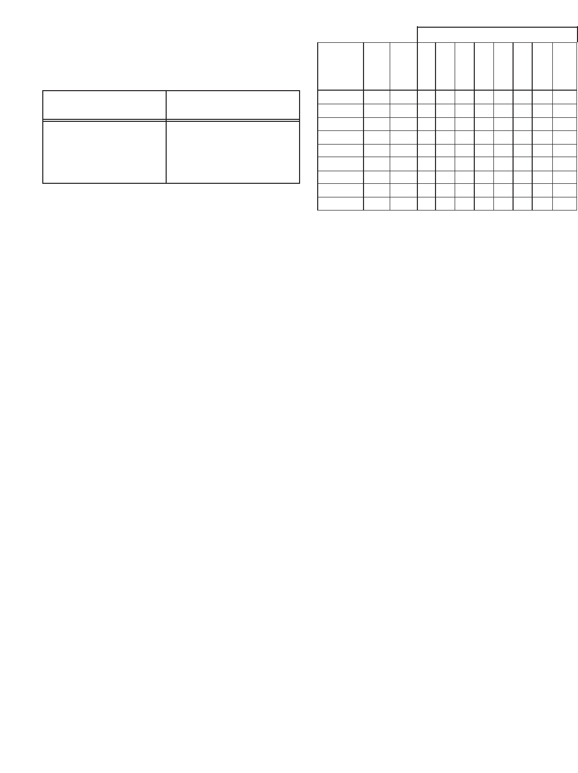
392.9(F)(2)
The fill areas for combinations of multiconductor
cables of any type installed in solid channel cable
tray.
392.10. Number of Single Conductor
Cables, Rated 2000 Volts or Less in Cable
Trays.
Installation of single conductors in cable tray is
restricted to industrial establishments where
conditions of maintenance and supervision assure
that only qualified persons will service the installed
cable tray systems. Single conductor cables for these
installations must be 1/0 or larger, and they may
not be installed in solid bottom cable trays.
392.10. Number of Single Conductor
Cables, Rated 2000 Volts or Less in Cable
Trays. (A) Ladder or Ventilated Trough
Cable Trays. (1) 1000 KCMIL or Larger
Cables
The sum of the diameters (Sd) of all single
conductor cables shall not exceed the cable tray
width.
392.10. Number of Single Conductor
Cables, Rated 2000 Volts or Less, in
Cable Trays. (A) Ladder or Ventilated
Trough Cable Trays. (2) 250 KCMIL to
1000 KCMIL Cables
Number Of 600 Volt Single Conductor Cables
That May Be Installed In Ladder Or Ventilated
Trough Cable Tray - Section 392.10(A) (2)
392.10. Number of Single Conductor
Cables, Rated 2000 Volts or Less in Cable
Trays. (A) Ladder or Ventilated Trough
Cable Trays. (3) 1000 KCMIL or Larger
Cables Installed With Cables Smaller Than
1000 KCMIL.
Such installations are very rare.
392.10. Number of Single Conductor
Cables, Rated 2000 Volts or Less in Cable
Trays. (A) Ladder or Ventilated Trough
Cable Trays. (4) Cables 1/0 Through 4/0
The sum of the diameters (Sd) of all 1/0 through
4/0 cables shall not exceed the inside width of the
cable tray.
35
Cable Tray Manual Cooper B-Line, Inc
Dia. (Note
Single In. Area #2)
Conductor (Note) Sq. 6 9 12 18 24 30 36 42
Size #1 In. In. In. In. In. In. In. In. In.
1/0 0.58 -- 10 15 20 31 41 51 62 72
2/0 0.62 -- 9 14 19 29 38 48 58 67
3/0 0.68 -- 8 13 17 26 35 44 52 61
4/0 0.73 -- 8 12 16 24 32 41 49 57
250 Kcmil 0.84 0.55 11 18 24 35 47 59 71 82
350 Kcmil 0.94 0.69 9 14 19 28 38 47 57 65
500 Kcmil 1.07 0.90 7 11 14 22 29 36 43 50
750 Kcmil 1.28 1.29 5 8 10 15 20 25 30 35
1000 Kcmil 1.45 -- 4 6 8 12 16 20 24 28
Cable Tray Width
Notes:
#1. Cable diameter's used are those for Okonite-
Okolon 600 volt single conductor power cables.
#2. 42 inch wide is ladder cable tray only.
#3. Such installations are to be made only in qualifying
industrial facilities as per Sections 392.3(B) &
(B)(1).
#4. To avoid problems with unbalanced voltages, the
cables should be bundled with ties every three feet
or four feet. The bundle must contain the circuit's
three phase conductors plus the neutral if one is
used.
#5. The single conductor cables should be firmly tied to
the cable trays at six foot or less intervals.
Solid Channel Maximum Allowable
Cable Tray Size Fill Area
2 Inch Wide 0.8 Square Inches
3 Inch Wide 1.1 Square Inches
4 Inch Wide 2.1 Square Inches
6 Inch Wide 3.2 Square Inches

392.10. Number of Single Conductor
Cables, Rated 2000 Volts or Less in Cable
Trays. (B) Ventilated Channel Cable Trays.
The sum of the diameters (Sd) of all single
conductors shall not exceed the inside width of the
ventilated cable channel.
Number Of 600 Volt Single Conductor Cables
That May Be Installed In A Ventilated Channel
Cable Tray - Section 392.10(B)
392.11. Ampacity of Cables Rated 2000
Volts or Less in Cable Trays.
(A) Multiconductor Cables.
Ampacity Tables 310.16 and 310.18 are to be
used for multiconductor cables which are installed in
cable tray using the allowable fill areas as per Section
392.9. The ampacities in Table 310.16 are based
on an ambient temperature of 30˚ Celsius. Conduit
and cable tray wiring systems are often installed in
areas where they will be exposed to high ambient
temperatures. For such installations, some designers
and engineers neglect using the Ampacity Correction
Factors listed below the Wire Ampacity Tables which
results in the conductor insulation being operated in
excess of its maximum safe temperature. These
correction factors must be used to derate a cable for
the maximum temperature it will be subjected to
anywhere along its length.
392.11(A)(1)
Section 310.15(B)(2)(a) refers to Section 392.11
which states that the derating information of Table
310.15(B)(2)(a) applies to multiconductor cables with
more than three current carrying conductors but not
to the number of conductors in the cable tray.
392.11(A)(2)
Where cable trays are continuously covered for more
than 6 feet (1.83m) with solid unventilated covers,
not over 95 percent of the allowable ampacities of
Tables 310.16 and 310.18 shall be permitted for
multiconductor cables.
This is for multiconductor cables installed using
Table 392.16 or 392.18. If these cables are installed
in cable trays with solid unventilated covers for more
than 6 feet the cables must be derated. Where cable
tray covers are to be used, it is best to use raised or
ventilated covers so that the cables can operate in a
lower ambient temperature.
392.11(A)(3)
Where multiconductor cables are installed in a
single layer in uncovered trays, with a maintained
spacing of not less than one cable diameter between
cables, the ampacity shall not exceed the allowable
ambient temperature corrected ampacities of
multiconductor cables, with not more than three
insulated conductors rated 0-2000 volts in free air, in
accordance with Section 310.15(C).
By spacing the cables one diameter apart, the
engineer may increase the allowable ampacities of
the cables to the free air rating as per Section
310.15(C) and Table B-310.3 in Appendix B.
Notice that the allowable fill of the cable tray has
been decreased in this design due to the cable
spacing.
36
Cooper B-Line, Inc Cable Tray Manual
Notes:
#1. Cable diameter's used are those for Okonite-
Okolon 600 volt single conductor power cables.
#2. Such installations are to be made only in qualifying
industrial facilities as per Sections 392.3(B) &
(B)(1).
#3. The phase, neutral, and EGCs cables are all
counted in the allowable cable fill for the ventilated
channel cable tray.
#4. To avoid problems with unbalanced voltages, the
cables should be bundled with ties every three feet
or four feet. The bundle must contain the circuit's
three phase conductors plus the neutral if one is
used. If a cable is used as the EGC, it should also
be in the cable bundle. If the designer desires, the
ventilated channel cable tray may be used as the
EGC as per Table 392.7(B)(2).
#5. The single conductor cables should be firmly tied to
the ventilated channel cable tray at six foot or less
intervals.
Single Diameter 3 Inch 4 Inch 6 Inch
Conductor Inches V. Channel V. Channel V. Channel
Size (Note #1) C.T. C.T. C.T.
1/0 AWG 0.58 5 6 10
2/0 AWG 0.62 4 6 9
3/0 AWG 0.68 4 5 8
4/0 AWG 0.73 4 5 8
250 Kcmil 0.84 3 4 7
350 Kcmil 0.94 3 4 6
500 Kcmil 1.07 2 3 5
750 Kcmil 1.28 2 3 4
1000 Kcmil 1.45 2 2 4
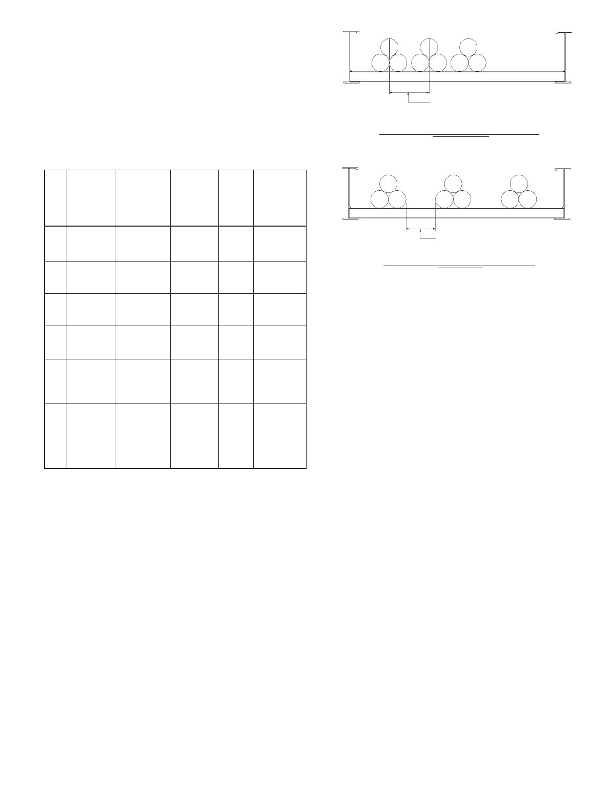
392.11. Ampacity of Cables Rated 2000
Volts or Less in Cable Trays. (B) Single
Conductor Cables.
Single conductor cables can be installed in a cable
tray cabled together (triplexed, quadruplexed, etc.) if
desired. Where the cables are installed according to
the requirements of Section 392.10, the ampacity
requirements are shown in the following chart as
per Section 392.11(B)(1), (2), (3), & (4):
392.12. Number of Type MV and Type
MC Cables (2001 Volts or Over) in Cable
Trays.
Sum the diameters of all the cables (Sd) to
determine the minimum required cable tray width.
Triplexing or quadruplexing the cables does not
change the required cable tray width. Whether the
cables are grouped or ungrouped, all installations
must be in a single layer.
392.13. Ampacity of Type MV and Type
MC Cables (2001 Volts or Over) in Cable
Trays. (A) Multiconductor Cables (2001
Volts or Over).
Provision No. 1: Where cable trays are
continuously covered for more than six feet
(1.83 m) with solid unventilated covers, not
more than 95% of the allowable ampacities
of Tables 310.75 and 310.76 shall be
permitted for multiconductor cables.
Cables installed in cable trays with solid
unventilated covers must be derated. Where cable
tray covers are to be used, it is best to use raised or
ventilated covers so that the cables can operate in a
lower ambient temperature.
37
Cable Tray Manual Cooper B-Line, Inc
Mult.
Solid Applicable Amp.
Sec. Cable Unventilated Ampacity Table Special
No. Sizes Cable Tray Tables Values Conditions
Cover (*) By
600 kcmil No Cover 310.17
(1) and Allowed and 0.75
Larger (**) 310.19
600 kcmil 310.17
(1) and Yes and 0.70
Larger 310.19
1/0 AWG No Cover 310.17
(2) through Allowed and 0.65
500 kcmil (**) 310.19
1/0 AWG 310.17
(2) through Yes and 0.60
500 kcmil 310.19
1/0 AWG Maintained
(3) & Larger No Cover 310.17 1.00 Spacing Of
In Single Allowed and One Cable
Layer (**) 310.19 Diameter
Single
Conductors 310.20 Spacing Of
(4) In Triangle No Cover [See NEC 2.15 x One
Config. Allowed Section 1.00 Conductor
1/0 AWG (**) 310.15(B)] O.D.
Between
and Larger Cables(***)
(*) The ambient ampacity correction factors must be used.
(**) At a specific position, where it is determined that the tray
cables require mechanical protection, a single cable tray cover of
six feet or less in length can be installed.
The wording of Section 392.11(B)(4) states that a spacing of
2.15 times one conductor diameter is to be maintained between
circuits. Two interpretations of this statement are possible.
Interpretation #1. - The 2.15 times one conductor diameter is
the distance between the centerlines of the circuits (the center
lines of the conductor bundles). Interpretation #2. - The 2.15
times one conductor diameter is the free air distance between the
adjacent cable bundles. The use of the word “circuit” is
unfortunate as its presence promotes Interpretation #1. An
installation based on Interpretation #1 is not desirable as a free
air space equal to 2.15 times one conductor diameter between
the cable bundles should be maintained to promote cable heat
dissipation.
Spacing Between Conductors
(2.15 x O.D. of Conductor)
Technically Desirable Installation
Spacing Between Conductors
(2.15 x O.D. of Conductor)
Technically Undesirable Installation
Interpretation #1
Interpretation #2
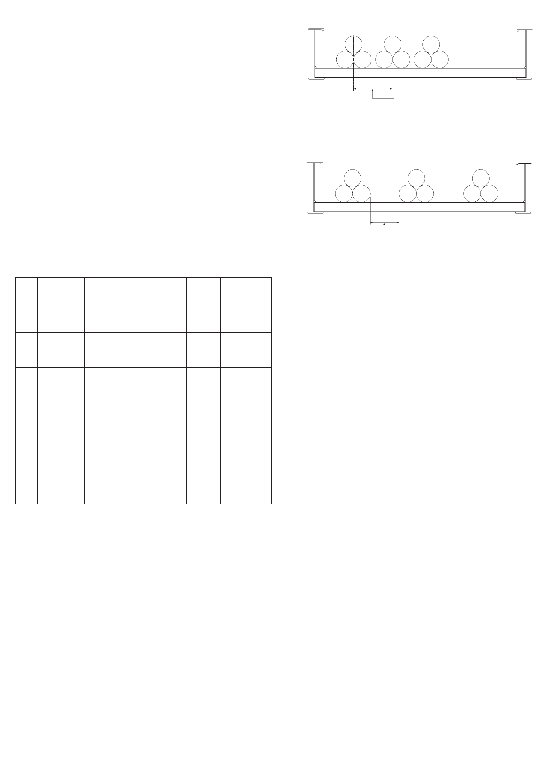
Provision No. 2: Where multiconductor
cables are installed in a single layer in
uncovered cable trays with a maintained
spacing of not less than one cable diameter
between cables, the ampacity shall not
exceed the allowable ampacities of Table
310.71 and 310.72.
If the cable tray does not have covers and the
conductors are installed in a single layer spaced not
less than one cable diameter apart, the cable
conductor ampacities can be 100 percent of the
ambient temperature corrected capacities in Tables
310.71 or 310.72.
392.13. Ampacity of Type MV and Type
MC Cables (2001 Volts or Over) in Cable
Trays. (B) Single Conductor Cables (2001
Volts or Over).
CABLE TRAY WIRING SYSTEM DESIGN
AND INSTALLATION HINTS.
Cable tray wiring systems should have a
standardized cabling strategy. Standard cable types
should be used for each circuit type. Most of the
following circuits should be included; feeder circuits,
branch circuits, control circuits, instrumentation
circuits, programmable logic controller input and
output (I/O) circuits, low level analog or digital
signals, communication circuits and alarm circuits.
Some cables may satisfy the requirements for
several circuit types. Minimizing the number of
different cables used on a project reduces installed
costs. Some companies have cable standards based
on volume usage to minimize the numbers of
different cables used on a project. For example: if a
6 conductor No. 14 control cable is needed but 7
conductor No. 14 control cable is stocked, a 7
conductor control cable would be specified and the
extra conductor would not be used. Following such a
practice can reduce the number of different cables
handled on a large project without increasing the
cost since high volume cable purchases result in cost
savings. Orderly record keeping also helps provide
quality systems with lower installation costs. The
following items should be included in the project's
cable records:
38
Cooper B-Line, Inc Cable Tray Manual
(*) The ambient ampacity correction factors must be used.
(**) At a specific position, where it is determined that the tray
cables require mechanical protection, a single cable tray cover of
six feet or less in length can be installed.
The wording of Section 392.13(B)(3) states that a spacing of
2.15 times one conductor diameter is to be maintained between
circuits. Two interpretations of this statement are possible.
Interpretation #1. - The 2.15 times one conductor diameter is
the distance between the centerlines of the circuits (the center
lines of the conductor bundles). Interpretation #2. - The 2.15
times one conductor diameter is the free air distance between the
adjacent cable bundles. The use of the word “circuit” is
unfortunate as its presence promotes Interpretation #1. An
installation based on Interpretation #1 is not desirable as a free
air space equal to 2.15 times one conductor diameter between
the cable bundles should be maintained to promote cable heat
dissipation.
Mult.
Solid Applicable Amp.
Sec. Cable Unventilated Ampacity Table Special
No. Sizes Cable Tray Tables Values Conditions
Cover (*) By
1/0 AWG No Cover 310.69
(1) and Allowed and 0.75
Larger (**) 310.70
1/0 AWG 310.69
(1) and Yes and 0.70
Larger 310.70
1/0 AWG Maintained
(2) & Larger No Cover 310.69 1.00 Spacing Of
In Single Allowed and One Cable
Layer (**) 310.70 Diameter
Single
Conductors Spacing Of
(3) In Triangle No Cover 310.67 2.15 x One
Config. Allowed and 1.00 Conductor
1/0 AWG (**) 310.68 O.D.
Between
and Larger Cables(***)
Spacing Between Conductors
(2.15 x O.D. of Conductor)
Technically Desirable Installation
Spacing Between Conductors
(2.15 x O.D. of Conductor)
Technically Undesirable Installation
Interpretation #1
Interpretation #2

39
Cable Tray Manual Cooper B-Line, Inc
•Cable Tray Tag Numbers - The tagging system
should be developed by the design personnel with
identification numbers assigned to cable tray runs on
the layout drawings. Cable tray tag numbers are
used for controlling the installation of the proper
cable tray in the correct location, routing cables
through the tray system and controlling the cable fill
area requirements.
•Cable Schedules - A wire management system
is required for any size project. Cable schedules
must be developed to keep track of the cables. This
is especially true for projects involving more than
just a few feeder cables. A typical cable schedule
would contain most or all of the following:
•The Cable Number, the Cable Manufacturer &
Catalog Number, Number of conductors, the
conductor sizes, and the approximate cable length.
•Cable Origin Location - The origin equipment
ID with the compartment or circuit number and
terminals on which the cable conductors are to be
terminated. It should also include the origin
equipment layout drawing number, and the origin
equipment connection diagram number.
•Cable Routing - Identifies the cable tray sections
or runs that a cable will occupy. Cable tray ID tag
numbers are used to track the routing.
•Cable Termination Location - The device or
terminal equipment on which the cable conductors
are to be terminated. It should also include the
termination equipment layout drawing number, and
the termination equipment connection diagram
number.
Some design consultants and corporate
engineering departments use spread sheets to
monitor the cable tray runs for cable fill. With such a
program, the cable tray fill area values for each
cable tray run or section can be continuously
upgraded. If a specified cable tray run or section
becomes overfilled, it will be flagged for corrective
action by the designer.
•Cable Installation Provisions - The cable tray
system must be designed and installed, to allow
access for cable installation. For many installations,
the cables may be hand laid into the cable trays and
no cable pulling equipment is required. There are
other installations where sufficient room must be
allotted for all the cable pulling activities and
equipment.
The cable manufacturers will provide installation
information for their cables such as maximum
pulling tension, allowable sidewall pressures,
minimum bending radii, maximum permissible
pulling length etc.. Lubricants are not normally used
on cables being installed in cable trays.
The engineer and designers should discuss in
detail the installation of the cables with the
appropriate construction personnel. This will help to
avoid installation problems and additional installation
costs. It is important that the cable pull is in the
direction that will result in the lowest tension on the
cables. Keep in mind there also needs to be room at
the ends of the pulls for the reel setups and for the
power pulling equipment. Cable pulleys should be
installed at each direction change. Triple pulleys
should be used for 90 degree horizontal bends and
all vertical bends. Single pulleys are adequate for
horizontal bends less than 90 degrees. Use rollers
in-between pulleys and every 10 to 20 feet
depending on the cable weight. Plastic jacketed
cables are easier to pull than are the metallic
jacketed cables and there is less chance of cable
damage. The pulling eye should always be attached
to the conductor material to avoid tensioning the
insulation. For interlocked armor cables, the
conductors and the armor both have to be attached
to the pulling eye.
Normally, the cables installed in cable trays are not
subjected to the damage suffered by insulated
conductors pulled into conduit. Depending on the
size of the insulated conductors and the conduit,
jamming can take place which places destructive
stresses on the cable insulation. In the October,
1991 issue of EC]&M magazine, the article on cable
pulling stated that 92 percent of the insulated
conductors that fail do so because they were
damaged in installation.
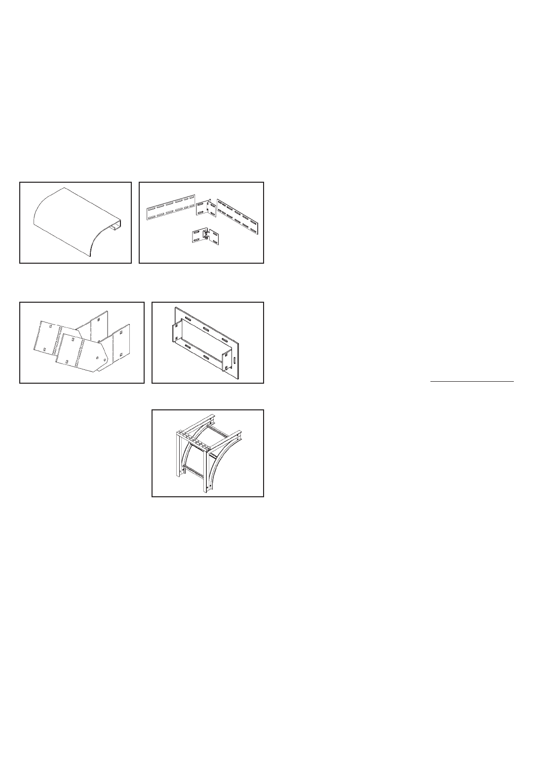
CABLE TRAY ACCESSORIES.
B-Line manufactures a full line of prefabricated
accessories for all types of B-Line cable trays. The
use of the appropriate accessories will provide
installation cost and time savings. In addition to
providing desirable electrical and mechanical
features for the cable tray system, the use of the
appropriate accessories improves the physical
appearance of the cable tray system. Some of the
most common accessories are shown below.
FIREPROOFING CABLE TRAY
Cable trays should not be encapsulated for fire
protection purposes other than for the short lengths
at fire rated walls unless the cables are adequately
derated. Encapsulation to keep fire heat out will also
keep conductor heat in. If conductors cannot
dissipate their heat, their insulation systems will
deteriorate. If the cable tray will be encapsulated,
the cable manufacturer should be consulted for
derating information.
CABLE TRAY MAINTENANCE AND
REPAIR
If the cable tray finish and load capacity is
properly specified and the tray is properly installed,
virtually no maintenance is required.
Pre-Galvanized - This finish is for dry indoor
locations. No maintenance is required.
Hot Dip Galvanized - This finish is maintenance
free for many years in all but the most severe
environments. If components have been cut or
drilled in the field, the exposed steel area should be
repaired with a cold galvanizing compound. B-Line
has a spray on zinc coating available which meets
the requirements of ASTM A780, Repair of Hot
Dip Finishes.
Aluminum - Our cable tray products are
manufactured from type 6063-T6 aluminum alloy
with a natural finish. The natural oxide finish is self
healing and requires no repair if it is field modified.
Non-metallic - Fabrication with fiberglass is
relatively easy and comparable to working with
wood. Any surface that has been drilled, cut,
sanded, or otherwise broken, must be sealed with
a comparable resin. Polyester or vinyl ester sealing
kits are available.
Cable tray should be visually inspected each year
for structural damage i.e., broken welds, bent rungs
or severely deformed side rails. If damage is evident,
from abuse or installation, it is recommended that
the damaged section of cable tray be replaced rather
than repaired. It is much easier to drop a damaged
section of tray out from under the cables than it is to
shield the cables from weld spatter.
40
Cooper B-Line, Inc Cable Tray Manual
Ladder Dropout Horizontal Adjustable
Splice
Frame Box Connector
Cable Support Fitting
Vertical Adjustable
Splice
41
Cable Tray Manual Cooper B-Line, Inc
CABLE TRAY. THERMAL CONTRACTION
AND EXPANSION
All materials expand and contract due to
temperature changes. Cable tray installations should
incorporate features which provide adequate
compensation for thermal contraction and
expansion. Installing expansion joints in the cable
tray runs only at the structure expansion joints does
not normally compensate adequately for the cable
tray's thermal contraction and expansion. The
supporting structure material and the cable tray
material will have different thermal expansion
values. They each require unique solutions to control
thermal expansion.
NEC®Section 300.7(B) states that 'Raceways
shall be provided with expansion joints where
necessary to compensate for thermal
expansion or contraction.' NEC®Section 392
does not address thermal contraction and expansion
of cable tray. One document which addresses
expansion is the NEMA Standards Publication No.
VE 2, Section 4.3.2. NEMA VE-2 Table 4-2 shows
the allowable lengths of steel and aluminum cable
tray between expansion joints for the temperature
differential values.
Reprinted with permission from NFPA 70-1999, the National Electrical Code®,
Copyright© 1998, National Fire Protection Association, Quincy, MA 02269. This reprinted
material is not the complete and official position of the National Fire Protection Association,
on the referenced subject which is represented only by the standard in its entirety.
Temp. Stainless Steel
Differential Steel Aluminum 304 316 FRP
°F (°C) Feet (m) Feet (m) Feet (m) Feet (m) Feet (m)
25 (-4) 512 (156.0) 260 (79.2) 347 (105.7) 379 (115.5) 667 (203.3)
50 (10) 256 (78.0) 130 (39.6) 174 (53.0) 189 (57.6) 333 (101.5)
75 (24) 171 (52.1) 87 (26.5) 116 (35.4) 126 (38.4) 222 (67.6)
100 (38) 128 (39.0) 65 (19.8) 87 (26.5) 95 (29.0) 167 (50.9)
125 (51) 102 (31.1) 52 (15.8) 69 (21.0) 76 (23.2) 133 (40.5)
150 (65) 85 (25.9) 43 (13.1) 58 (17.7) 63 (19.2) 111 (33.8)
175 (79) 73 (22.2) 37 (11.3) 50 (15.2) 54 (16.4) 95 (28.9)
Table 4-2
Maximum Spacing Between Expansion Joints
That Provide For One Inch (25.4 mm) Movement
For a 100°F differential (winter to summer), a steel cable tray will require an expansion
joint every 128 feet and an aluminum cable tray every 65 feet. The temperature at the
time of installation will dictate the gap setting.
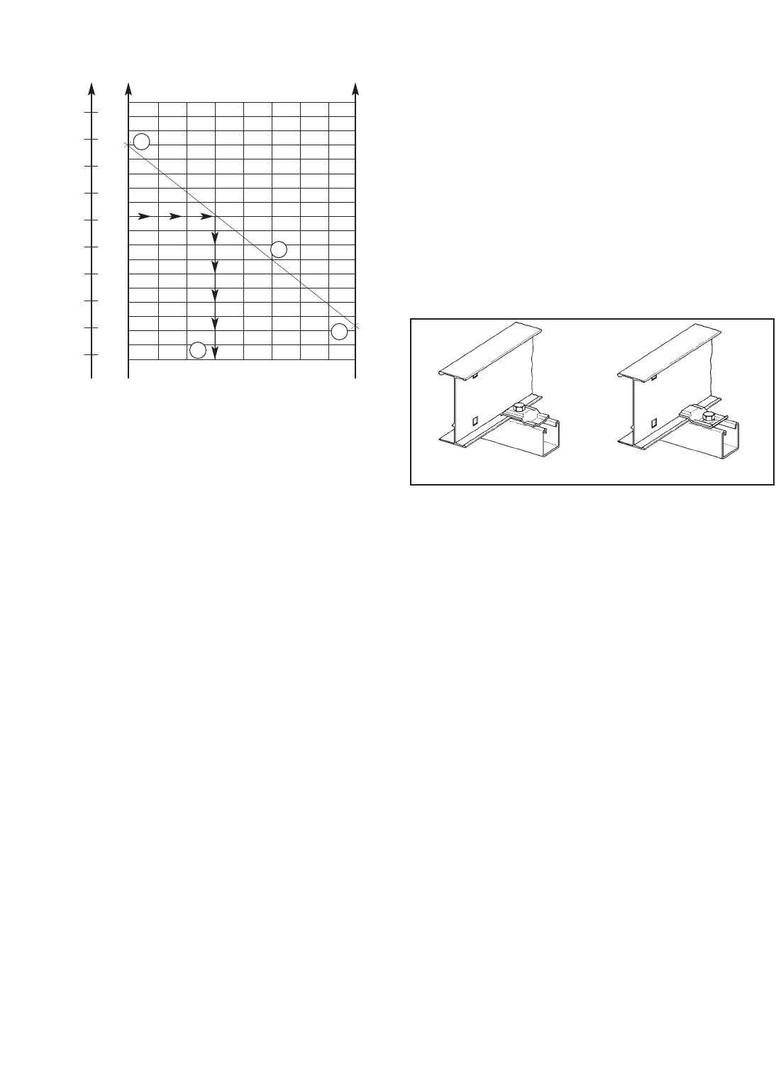
42
Cooper B-Line, Inc Cable Tray Manual
The Gap Setting of the Expansion Joint Splice
Plate is used as follows per the example indicated in
VE-2 Figure 4.13B.
Step 1. Plot the highest expected cable tray metal
temperature during the year on the maximum
temperature vertical axis. Example's Value: 100
Degrees F.
Step 2. Plot the lowest expected cable tray metal
temperature during the year on the minimum
temperature vertical axes. Example's Value: - 28
Degrees F.
Step 3. Draw a line between these maximum and
minimum temperature points on the two vertical
axis.
Step 4. To determine the required expansion joint
gap setting at the time of the cable tray's installation:
Plot the cable tray metal temperature at the time of
the cable tray installation on the maximum
temperature vertical axis (Example's Value: 50
Degrees F). Project over from the 50 Degrees F
point on the maximum temperature vertical axis to
an intersection with the line between the maximum
and minimum cable tray metal temperatures. From
this intersection point, project down to the gap
setting horizontal axis to find the correct gap setting
value (Example's Value: 3/8inch gap setting). This is
the length of the gap to be set between the cable
tray sections at the expansion joint.
The plotted High - Low Temperature Range in
Figure 4-13B is 128° F. The 125° F line in Table
4-1 shows that installations in these temperature
ranges would require 3/8” expansion joints
approximately every 102 feet for Steel and every
52 feet for Aluminum cable tray.
Another item essential to the operation of the
cable tray expansion splices is the type of hold down
clamps used. The cable tray must not be clamped to
each support so firmly that the cable tray cannot
contract and expand without distortion. The cable
tray needs to be anchored at the support closest to
the midpoint between the expansion joints with
hold down clamps and secured by expansion
guides at all other support locations.The expansion
guides allow the cable tray to slide back and forth as
it contracts and expands. Supports must also be
located on both sides of an expansion splice. The
supports should be located within two feet of the
expansion splice to ensure that the splice will
operate properly. If these guidelines for cable tray
thermal contraction and expansion are not followed,
there is the potential for the cable trays to tear loose
from their supports, and for the cable trays to bend
and collapse.
Max. Temp. Min. Temp.
Figure 4.13B
Gap Setting Of Expansion Splice Plate
1" (25.4 mm) Gap Maximum
130
110
90
70
50
30
10
-10
-30
50
C° F° F°
40
30
20
10
0
-10
-20
-30
-40
130
110
90
70
50
30
10
-10
-30
0
1/85/8
1/2
3/8
1/4
1
7/8
3/4
Gap Setting in Inches
Metal Temperature At Time
Of Installation (F° or C°)
As a clamp. As a guide.
1
2
3
4

43
Cable Tray Manual Cooper B-Line, Inc

44
Cooper B-Line, Inc Cable Tray Manual
Appendix Pages
Appendix Sheet 1 ........................................................................................................ 45
Temperature Rise Tests, Cable Tray Connectors, Class II
Aluminum & Steel Ladder Tray
Appendix Sheet 2 ........................................................................................................ 46
Temperature Rise Tests, Conduit Clamps For Bonding Rigid
Conduit To Cable Tray
Appendix Sheet 3 ........................................................................................................ 47
Example - NEC®Section 392.9(A)(1)
Appendix Sheet 4 ........................................................................................................ 48
Example - NEC®Section 392.9(A)(2)
Appendix Sheet 5 ........................................................................................................ 49
Example - NEC®Section 392.9(A)(3)
Appendix Sheet 6 ........................................................................................................ 50
Example - NEC®Section 392.9(B)
Appendix Sheet 7 ........................................................................................................ 51
Table 250.122 Minimum Size EGC for Raceway and Equipment
Appendix Sheet 8 ................................................................................................ 52 - 53
Cable Tray Sizing Flowchart
Appendix Sheet 9 ................................................................................................ 54 - 55
Cable Tray Installation & Specification Checklist
Appendix Sheet 10 ...................................................................................................... 56
Additional Cable Tray Resources and Engineering Software
Appendix Sheet 11 ...................................................................................................... 57
B-Line Wire Management Resources
45
Cable Tray Manual Cooper B-Line, Inc
Appendix Sheet 1
TABLE I
TEMPERATURE RISE TESTS, CABLE TRAY CONNECTORS,
CLASS II ALUMINUM LADDER CABLE TRAY
TABLE II
TEMPERATURE RISE TESTS, CABLE TRAY CONNECTORS,
CLASS II STEEL LADDER CABLE TRAY
Test Connector Data
Current Test I2TC1 C2 C3
Amps Time
And Cycles mult. Type No. & Temp. Type No. & Temp. Type No. & Temp.
Fuse by Of Type Rise Of Type Rise Of Type Rise
Size* 106Connector Bolts °C Connector Bolts °C Connector Bolts °C
1,980 52 3.4 Adj. Vert. 4 2 No. 6 CU AL-CU 10 Rigid 2 3
200A, FU 1 Bolt** Bond Lugs
1,970 394 25.5 Adj. Vert. 4 9 No. 6 CU AL-CU *** Rigid 2 15
400A, FU 1 Bolt** Bond Lugs
1,960 8100 51.8 Adj. Vert. 4 18 Rigid 4 23 Rigid 2 32
400A, FU 1 Bolt**
12,000 120 288 Adj. Vert. 4 94 Adj. Vert. 4 89 Rigid 4 81
2 Bolts** 2 Bolts**
12,000 123 295 Rigid 4 70 Rigid 4 87 Rigid 4 85
34,000 13 250 Rigid 4 71 Rigid 4 57 Rigid 4 69
Test Connector Data
Current Test I2TC1 C2 C3
Amps Time
And Cycles mult. Type No. & Temp. Type No. & Temp. Type No. & Temp.
Fuse by Of Type Rise Of Type Rise Of Type Rise
Size* 106Connector Bolts °C Connector Bolts °C Connector Bolts °C
7,900 Adj. Vert. 3/0 CU AL-CU Rigid
1,200A 66 69 1 Bolt** 4 6 Bond Lugs 18 Clean 2 8
Fuse Steel Steel
7,900 Rigid 3/0 CU AL-CU Rigid
1,200A 82 85 Corroded 4 10 Bond Lugs 22 Clean 2 9
Fuse Steel Steel
12,000 120 288 Rigid 2 50 3/0 CU AL-CU 104 Rigid 2 32
Corroded Nylon Bond Lugs Clean Steel
12,000 124 297 Rigid 4 40 Rigid 4 46 Rigid 4 21
Corroded Steel Corroded Lugs Clean Steel
34,600 14 280 Rigid 2 34 3/0 CU AL-CU 75 Rigid 2 29
Corroded Nylon Bond Lugs Clean Steel
34,400 14 276 Rigid 4 28 Rigid 4 35 Rigid 4 20
Corroded Nylon Corroded Steel Clean Steel
*Test current was interrupted in a predetermined time when a fuse was not used.
** 1 or 2 Bolts - Number of bolts installed on the adjustable vertical connector hinge.
*** The No. 6 bonding jumper melted and opened the circuit when protected by 400A fuse.
(See Page 29 - Figure 1 for Temperature Rise Test illustration)
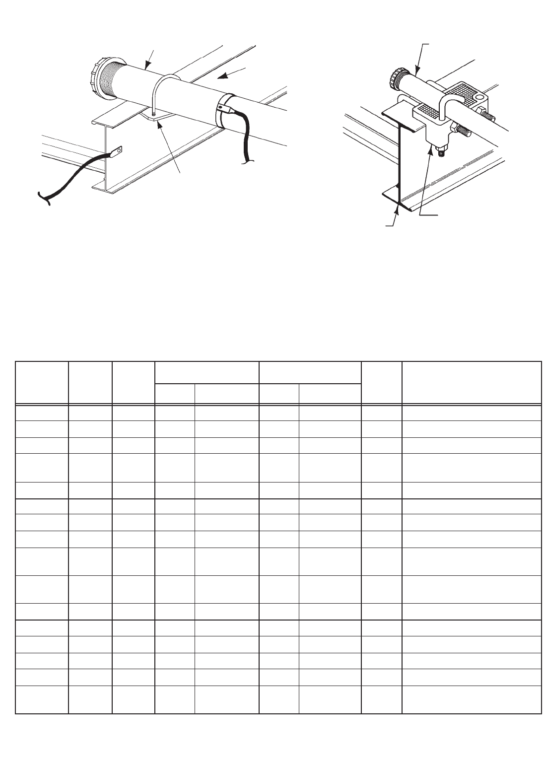
46
Cooper B-Line, Inc Cable Tray Manual
TABLE III
TEMPERATURE RISE TESTS, CONDUIT CLAMPS
FOR BONDING RIGID CONDUIT TO CABLE TRAY
Test Test I2TRigid Conduit Cable Tray Temp.
Current Time mult. Rise Condition After Test
Amperes Cycles 106Size Material Class Material °C
36,000 16 344.7 4" Aluminum II Aluminum 19 No arcing or damage
20,900 60.5 441.2 4" Aluminum II Aluminum 70 No arcing or damage
12,100 178 433.3 4" Aluminum II Aluminum 74 No arcing or damage
21,000 20 146.8 4" Steel II Steel (?) Zinc melted at point where
conduit contacted with tray
3,260 900 159.5 4" Steel II Steel 63 No arcing or damage
21,000 30 220 2" Aluminum II Aluminum 21 No arcing or damage
12,100 120.5 294.2 2" Aluminum II Aluminum 59 No arcing or damage
8,000 245 261.1 2" Aluminum II Aluminum 44 No arcing or damage
21,000 14 103.8 2" Steel II Steel 62 Zinc melted at point where
conduit contacted with tray
12,000 60.5 145.4 2" Steel II Steel 22 Slight arc between
clamp and tray
3,240 600 104.9 2" Steel II Steel 49 No arcing or damage
21,000 20 146.8 1" Aluminum II Aluminum 20 No arcing or damage
12,200 60.5 150.3 1" Aluminum II Aluminum 24 No arcing or damage
12,100 14.5 35.3 1" Steel II Steel 6 No arcing or damage
8,000 63.5 67.84 1" Steel II Steel 59 No arcing or damage
1,980 44.5 2.9 1" Steel II Steel 1 No arcing or damage
200A FU
Appendix Sheet 2
Conduit
UL Listed
Conduit Clamp
(9ZN-1158)
Cable Tray
Conduit
Cable Tray
Right Angle
Beam Clamp To
Current
Source
To
Current
Source Conduit Clamp DetailTest Set-Up
CIRCUIT ARRANGEMENT FOR RIGID CONDUIT
TEMPERATURE RISE TESTS
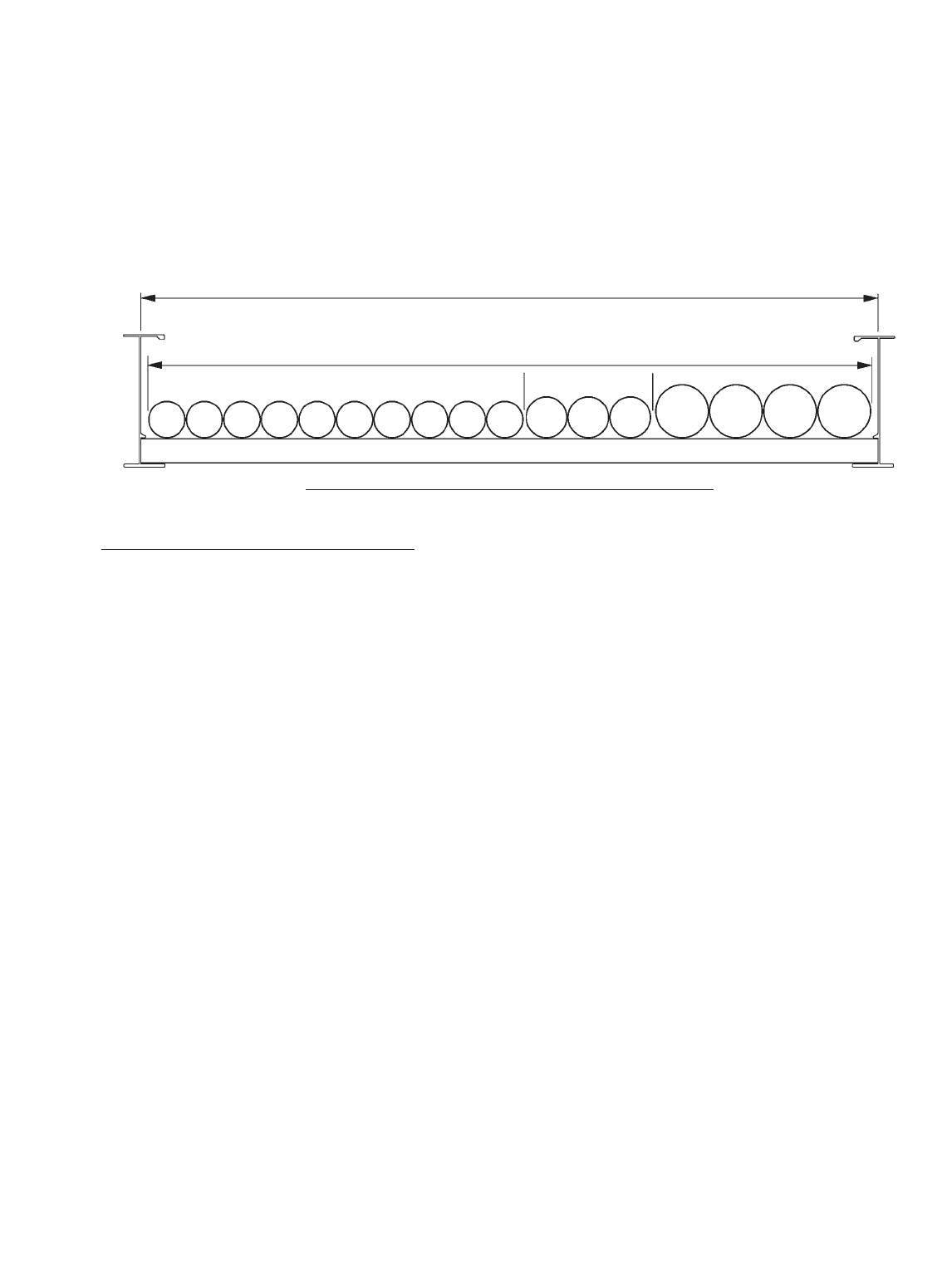
47
Cable Tray Manual Cooper B-Line, Inc
Appendix Sheet 3
Example - NEC®Section 392.9(A)(1)
Width selection for cable tray containing 600 volt multiconductor cables, sizes #4/0 AWG and larger
only. Cable installation is limited to a single layer. The sum of the cable diameters (Sd) must be equal
to or less than the usable cable tray width.
Cable tray width is obtained as follows:
(D) (N) Multiply (D) x (N)
Item List List Cable List Number Subtotal of the
Number Cable Sizes Outside of Cables Sum of the Cables
Diameter Diameters (Sd)
1. 3/C - #500 kcmil 2.26 inches 4 9.04 inches
2. 3/C - #250 kcmil 1.76 inches 3 5.28 inches
3. 3/C - #4/0 AWG 1.55 inches 10 15.50 inches
The sum of the diameters (Sd) of all cables (Add Sds for items 1, 2, & 3.)
9.04 inches + 5.28 inches + 15.50 inches = 29.82 inches (Sd)
A cable tray with a usable width of 30 inches is required. For
a 10% increase in cost a 36 inch wide cable tray could be
purchased which would provide for some future cable additions.
Notes:
1. The cable sizes used in this example are a random selection.
2. Cables - copper conductors with cross linked polyethylene insulation and a PVC jacket.
(These cables could be ordered with or without an equipment grounding conductor.)
3. Total cable weight per foot for this installation.
61.4 lbs./ft. (without equipment grounding conductors)
69.9 lbs./ft. (with equipment grounding conductors)
This load can be supported by a load symbol "B" cable tray - 75 lbs./ft.
30" Usable Cable Tray Width
29.82" = Equals Cable Sd
Cross Section Of The Cables And The Cable Tray
3333333333 222 1111
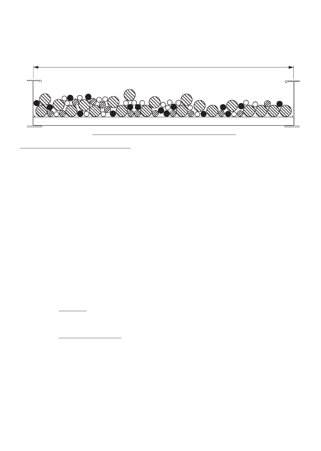
48
Cooper B-Line, Inc Cable Tray Manual
Appendix Sheet 4
Example - NEC®Section 392.9(A)(2)
Width selection for cable tray containing 600 volt multiconductor cables, sizes #3/0 AWG and
smaller. Cable tray allowable fill areas are listed in Column 1 of Table 392.9.
Cable tray width is obtained as follows:
(A) (N) Multiply (A) x (N)
Item List List Cable List Total of the
Number Cable Sizes Cross Sectional Number Cross Sectional
Areas of Cables Area for Each Item
1. 3/C #12 AWG 0.17 sq. in. 20 3.40 sq. in.
2. 4/C #12 AWG 0.19 sq. in. 16 3.04 sq. in.
3. 3/C #6 AWG 0.43 sq. in. 14 6.02 sq. in.
4. 3/C #2 AWG 0.80 sq. in. 20 16.00 sq. in.
Method 1.
The sum of the total areas for items 1, 2, 3, & 4:
3.40 sq. in. + 3.04 sq. in. + 6.02 sq. in. + 16.00 sq. in. = 28.46 sq. inches
From Table 392.9 Column 1 a 30 inch wide tray with an allowable fill area of 35 sq. in.
must be used. The 30 inch cable tray has the capacity for additional future cables (6.54
sq. in. additional allowable fill area can be used.)
Method 2.
The sum of the total areas for items 1, 2, 3, & 4 multiplied by
3.40 sq. in. + 3.04 sq. in. + 6.02 sq. in. + 16.00 sq. in. = 28 46 sq. in.
Use a 30 inch wide cable tray.
Notes:
1. The cable sizes used in this example are a random selection.
2. Cables - copper conductors with cross linked polyethylene insulation and a PVC jacket.
(These cables could be ordered with or without an equipment grounding conductor.)
3. Total cable weight per foot for this installation.
31.9 lbs./ft. (Cables in this example do not contain equipment grounding conductors.)
This load can be supported by a load symbol "A" cable tray - 50 lbs./ft.
30" Usable Cable Tray Width
Cross Section Of The Cables And The Cable Tray
( )
6 in.
7 sq. in. = cable tray width required
( )
28.46 sq. in. x 6 in.
7 sq. in. = 24.39 inch cable tray width required
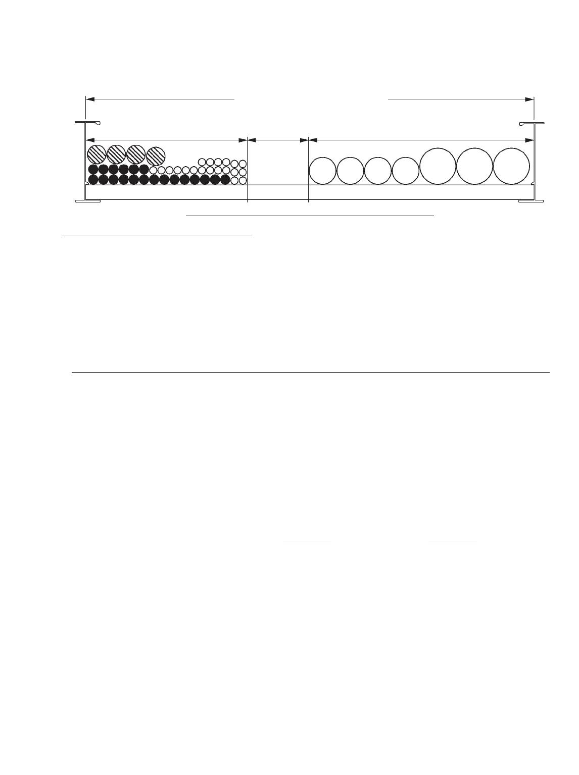
49
Cable Tray Manual Cooper B-Line, Inc
Example - NEC®Section 392.9(A)(3)
Width selection for cable tray containing 600 volt multiconductor cables, sizes #4/0 AWG and larger
(single layer required) and #3/0 AWG and smaller. These two groups of cables must have dedicated
areas in the cable tray.
Cable tray width is obtained as follows:
A - Width required for #4/0 AWG and larger multiconductor cables -
(D) (N) Multiply (D) x (N)
Item List List Cable List Number Subtotal of the
Number Cable Sizes Outside of Cables Sum of the Cables
Diameter Diameters (Sd)
1. 3/C - #500 kcmil 2.26 inches 3 6.78 inches
2. 3/C - #4/0 AWG 1.55 inches 4 6.20 inches
Total cable tray width required for items 1 & 2 = 6.78 inches + 6.20 inches = 12.98 inches
B - Width required for #3/0 AWG and smaller multiconductor cables -
(A) (N) Multiply (A) x (N)
Item List List Cable List Number Total of the
Number Cable Sizes Cross Sectional of Cables Cross Sectional Area
Area For Each Item
3. 3/C #12 AWG 0.17 sq. in. 20 3.40 sq. in.
4. 3/C #10 AWG 0.20 sq. in. 20 4.00 sq. in.
5. 3/C #2 AWG 0.80 sq. in. 4 3.20 sq. in.
Total cable tray width required for items 3, 4, & 5
Actual cable tray width is A - Width (12.98 in.) + B - Width (9.09 in.) = 22.07 inches
A 24 inch wide cable tray is required. The 24 inch cable tray has the capacity for additional
future cables (1.93 inches or 2.25 sq. inches allowable fill can be used).
Notes:
1. This ratio is the inside width of the cable tray in inches divided by its maximum fill area in
sq. inches from Column 1 Table 392.9.
2. The cable sizes used in this example are a random selection.
3. Cables - copper conductors with cross linked polyethylene insulation and a PVC jacket.
4. Total cable weight per foot for this installation.
40.2 lbs./ft. (Cables in this example do not contain equipment grounding conductors.)
This load can be supported by a load symbol "A" cable tray - 50 lbs./ft.
24" Usable Cable Tray Width
9.09" 1.93" 12.98"
Cross Section Of The Cables And The Cable Tray
2222 111
Appendix Sheet 5
(3.40 sq. in. + 4.00 sq. in. + 3.20 sq. in.) = (10.6 sq. in.) = 9.09 inches
( )
6 in.
7 sq. in. ( )
6 in.
7 sq. in.
1 1
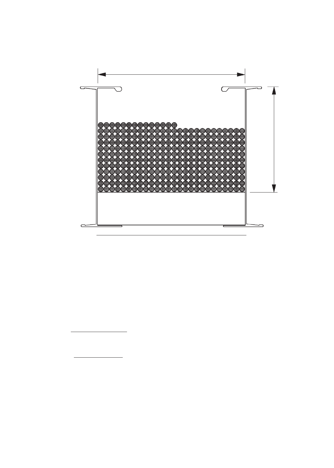
50
Cooper B-Line, Inc Cable Tray Manual
Appendix Sheet 6
Example - NEC®Section 392.9(B)
Cable Tray containing Type ITC or Type PLTC Cables
50% of the cable tray useable cross sectional area can contain type PLTC cables
4 inches x 6 inches x .050 = 12 square inches allowable fill area.
2/C - #16 AWG 300 volt shielded instrumentation cable O.D. = 0.224 inches.
Cross Sectional Area = 0.04 square inches.
Notes:
1. The cable sizes used in this example are a random selection.
2. Cables - copper conductors with PVC insulation, aluminum/mylar shielding, and PVC jacket.
6" Usable Cable Tray Width
4" Usable
Cable Tray
Depth
Cross Section Of The Cables And The Cable Tray
= 300 cables can be installed in this cable tray.
12 sq. in.
0.04 sq. in./cable
= 11.54 rows can be installed in this cable tray.
300 cables
26 cables/rows

51
Cable Tray Manual Cooper B-Line, Inc
Appendix Sheet 7
Reprinted with permission from NFPA 70-1999, the National Electrical Code®, Copyright© 1998, National Fire
Protection Association, Quincy, MA 02269. This reprinted material is not the complete and official position of the National
Fire Protection Association, on the referenced subject which is represented only by the standard in its entirety.
Table 250.122. Minimum Size Equipment Grounding
Conductors for Grounding Raceways and Equipment
Rating or Setting of Size
Automatic Overcurrent (AWG or kcmil)
Device in Circuit Ahead
of Equipment, Conduit, Aluminum or
etc., Not Exceeding Copper-Clad
(Amperes) Copper Aluminum*
15 14 12
20 12 10
30 10 8
40 10 8
60 10 8
100 8 6
200 6 4
300 4 2
400 3 1
500 2 1/0
600 1 2/0
800 1/0 3/0
1000 2/0 4/0
1200 3/0 250
1600 4/0 350
2000 250 400
2500 350 600
3000 400 600
4000 500 800
5000 700 1200
6000 800 1200
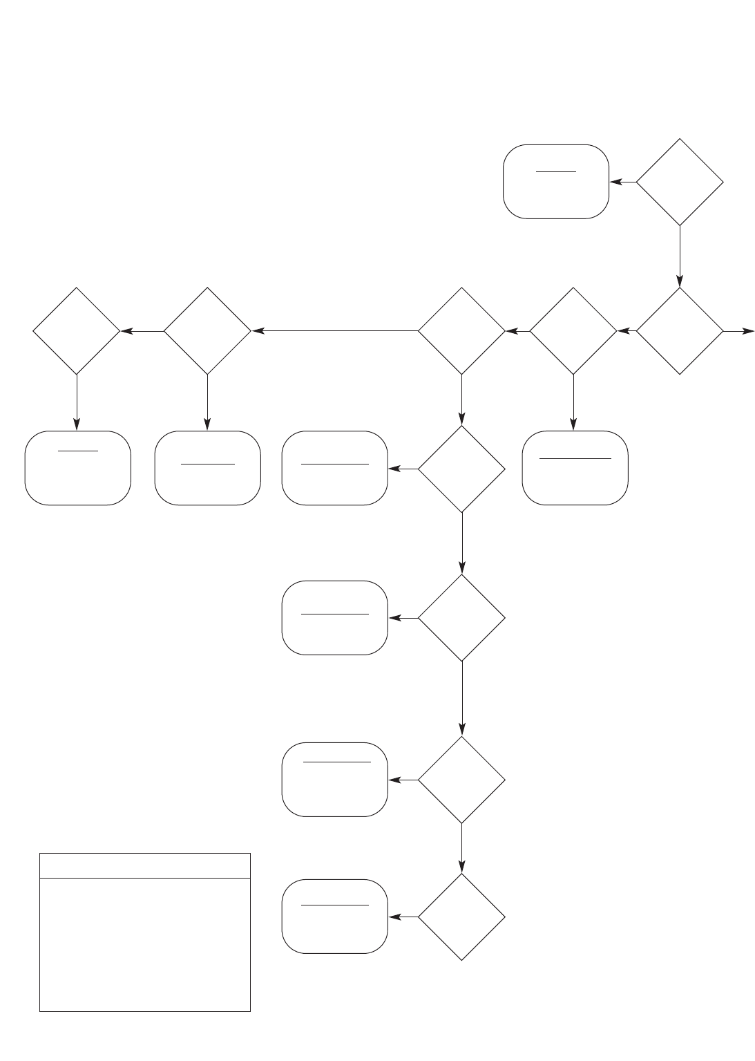
52
Cooper B-Line, Inc Cable Tray Manual
CABLE TRAY SIZING FLOWCHART
Appendix Sheet 8
392.12
W ≥Sd
(single layer)
392.3(B)(1)(a)
Not permitted
by the NEC®
392.10
Not
recognized by
the NEC®
392.10(B)
W ≥Sd 392.10(A)(1)
W ≥Sd
392.10(A)(2)
W ≥A/1.1
Note: The value “A”
only applies to cables
250 up to 1000kcmil.
The value “sd” only
applies to 1000 kcmil
and larger cables.
Note: Use when mixing
250 thru 1000 kcmil
cables with cables larger
than 1000 kcmil.
392.10(A)(3)
392.10(A)(4)
W ≥Sd
(9” max. RS)
2000V
or less
cables
Multi-
conductor
cables
S/C 1/0
or larger
Ladder
or Vented
Trough
Tray
S/C
1000
kcmil or
larger
S/C
250
kcmil up to
1000
kcmil
S/C
250 kcmil
and
larger
S/C 1/0
thru 4/0
Vented
Channel
Tray
Solid
Bottom
Tray
W ≥A/1.1 +Sd
No
No
No
No
No No No
No
Yes
Yes
Yes
Yes
YesYes Yes
Yes
Yes
Continued
on next
page
Yes
Legend
W = Cable Tray Width
D = Cable Tray Load Depth
Sd = Sum of Cable Diameters
A = Sum of Cable Areas
S/C = Single Conductor
M/C = Multiconductor Cables
RS = Ladder Rung Spacing
Start
Here
Sizing Cable Tray Per NEC 392
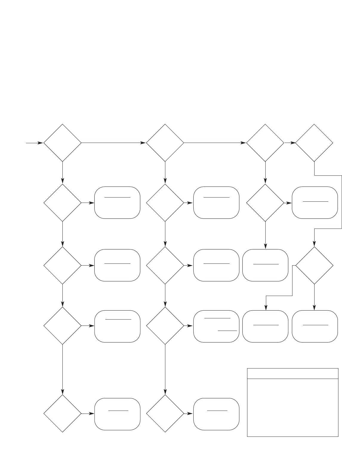
53
Cable Tray Manual Cooper B-Line, Inc
CABLE TRAY SIZING FLOWCHART
Appendix Sheet 8
392.9(E)(1)
W x D ≥1.6A
392.9(A)(1)
W ≥Sd
(single layer)
392.9(C)(1)
W ≥Sd/0.9
(single layer)
Note: The value “A”
only applies to cables
smaller than 4/0.
The value “Sd” only
applies to 4/0 and
larger cables, which
must be single layer
Note: The value “A”
only applies to cables
smaller than 4/0.
The value “Sd” only
applies to 4/0 and
larger cables, which
must be single layer
392.9(A)(3)
Vented
Channel
Tray
Solid
Channel
Tray
Solid
Bottom
Tray
Ladder
or Vented
Trough
Tray
One M/C
only
M/C 4/0
or larger
M/C 4/0
or larger
392.9(E)(2)
W x D ≥2.9A
392.9(F)(1)
W x D ≥1.9A
392.9(F)(2)
W x D ≥3.2A
392.9(A)(2)
W ≥A/1.2 392.9(C)(2)
W ≥A/0.9
M/C
smaller
than 4/0
One
M/C
Only
M/C
smaller
than 4/0
M/C
smaller than
4/0, with
4/0 or
larger
M/C
control
and/or
signal
W ≥A/1.2 + Sd
No NoNo
NoNo
NoNo
No No No
392.9(B)
W x D ≥2A
392.9(C)(3)
A + Sd
0.9
M/C
smaller than
4/0, with
4/0 or
larger
M/C
control
and/or
signal
W ≥
392.9(D)
W x D ≥2.5A
YesYes
Yes NoYes
Yes
Yes
Yes
YesYes
Yes
Yes Yes Yes
Yes
Legend
W = Cable Tray Width
D = Cable Tray Load Depth
Sd = Sum of Cable Diameters
A = Sum of Cable Areas
S/C = Single Conductor
M/C = Multiconductor Cables
RS = Ladder Rung Spacing
Ampacity: See pages 36 - 38 for information on cable ampacity that
might affect the cable tray sizing flowchart.
See pages 15 - 17 for information on hazardous
(classified) areas that might affect the cable tray sizing
flowchart.

54
Cooper B-Line, Inc Cable Tray Manual
Material NEMA Load Depth*
Aluminum ❏2” ** ❏
Pre-Galvanized Steel ❏3” ❏
Hot-Dip Galvanized Steel ❏4” ❏
304 Stainless Steel ❏5” ❏
316 Stainless Steel ❏6” ❏
Fiberglass-Polyester Resin ❏* Load depth is 1” less than siderail height.
Fiberglass-Vinyl Ester Resin ❏** Fiberglass and wire mesh.
Width Bottom Styles Length Fitting Radius
6” ❏6” ❏Metallic 12” ❏
9” ❏9” ❏120” ❏24” ❏
12” ❏12” ❏144” ❏36” ❏
18” ❏18” ❏240” ❏48” ❏
24” ❏Ventilated Trough ❏288” ❏
30” ❏Solid Trough ❏ Non-Metallic
36” ❏Solid Bottom ❏120” ❏
42” ❏240” ❏
Tray Series NEMA Class
A (50 lbs./ft.) ❏
B (75 lbs./ft.) ❏
B-Line Series OR C (100 lbs./ft.) ❏
Support Span ft.
Load Rating lbs./ft.
Safety Factor
CABLE TRAY INSTALLATION & SPECIFICATION CHECKLIST
Appendix Sheet 9
Project Information
Project Name: #
Location:
Contractor/Engineer:
Phone:
Project Information
Cable Tray
Distributor Name:
Location:
Contact:
Phone: Fax:

55
Cable Tray Manual Cooper B-Line, Inc
CABLE TRAY INSTALLATION & SPECIFICATION CHECKLIST
Appendix Sheet 9
Material Width
Aluminum ❏3” ❏
Pre-Galvanized Steel ❏4” ❏
Hot-Dip Galvanized Steel ❏6” ❏
304 Stainless Steel ❏8” * ❏
316 Stainless Steel ❏* Fiberglass only.
Fiberglass-Polyester Resin ❏
Fiberglass-Vinyl Ester Resin ❏Fitting Radius
Type 0” ❏
Ventilated ❏6” ❏
Non-Ventilated ❏12” ❏
24” ❏
36” ❏
Cable Channel
System Depth*
Data-Track ❏Straight Rung ❏
Verti-Rack ❏2” ❏
Half-Rack ❏3” ❏
Multi-Tier Half Rack ❏4” ❏
6” ❏
Width* Rung Spacing* Tiers* Length
3” ❏6” ❏2❏120” ❏
6” ❏9” ❏3❏144” ❏
9” ❏12” ❏ 4❏
12” ❏18” ❏5❏
18” ❏24” ❏6❏
24” ❏
* Options shown are not available for all systems. Please check B-Line Cent-R-Rail Catalog for availability.
Cent-R-Rail
Width* Depth* Wire Mesh Size Length
2” ❏1” ❏2 x 4 118” (3 meters)
4” ❏2” ❏
6” ❏4” ❏
8” ❏
12” ❏* Widths shown are not available for all depths.
18” ❏Please check B-Line Wire Basket Catalog for availability.
24” ❏
Wire Basket Tray

56
Cooper B-Line, Inc Cable Tray Manual
1 NEMA Standard VE-2, Section 4, Installation 4.3 Straight Section Installation - 4.3.1. Horizontal
Cable Tray Straight Sections states that straight section lengths should be equal to or greater than
the span length to ensure not more than one splice between supports.
Additional Cable Tray Resources
Cable Tray Institute National Electrical Manufacturers Association
1300 N. 17th Street 1300 N. 17th Street
Rosslyn, VA 22209 Rosslyn, VA 22209
www.cabletrays.com www.nema.org
B-Line Engineering Software
TrayCAD®
TrayCAD®is a Cable Tray layout design program that works within the AutoCAD®
environment. TrayCAD®is a windows based program and installs as an add-on to your
AutoCAD®system. Use the TrayCAD®toolbar to add cable tray to your existing plans by
drawing a single centerline representation of the tray run. Then, with the click of a button, the
program will build a full-scale 3-D wire-frame model of the cable tray and all the appropriate
fittings. The program also automatically creates a Bill of Material and contains a library of
modifiable details.
Runway Router®
Runway Router®is a cable ladder runway (ladder rack) layout design program that works within
your AutoCAD®environment. Use the commands from the Runway Router®toolbar to layout
runway, relay racks and electronic cabinets. Add cable tray or Cent-R-Rail®to your existing
plans by drawing a single centerline representation of the cable run. Then, with the click of a
button, the program will build a full-scale 3-D wire-frame model of the cable runway and all the
appropriate connectors and fittings. The program also automatically creates a Bill of Material
and contains a library of modifiable details.
Footnotes:
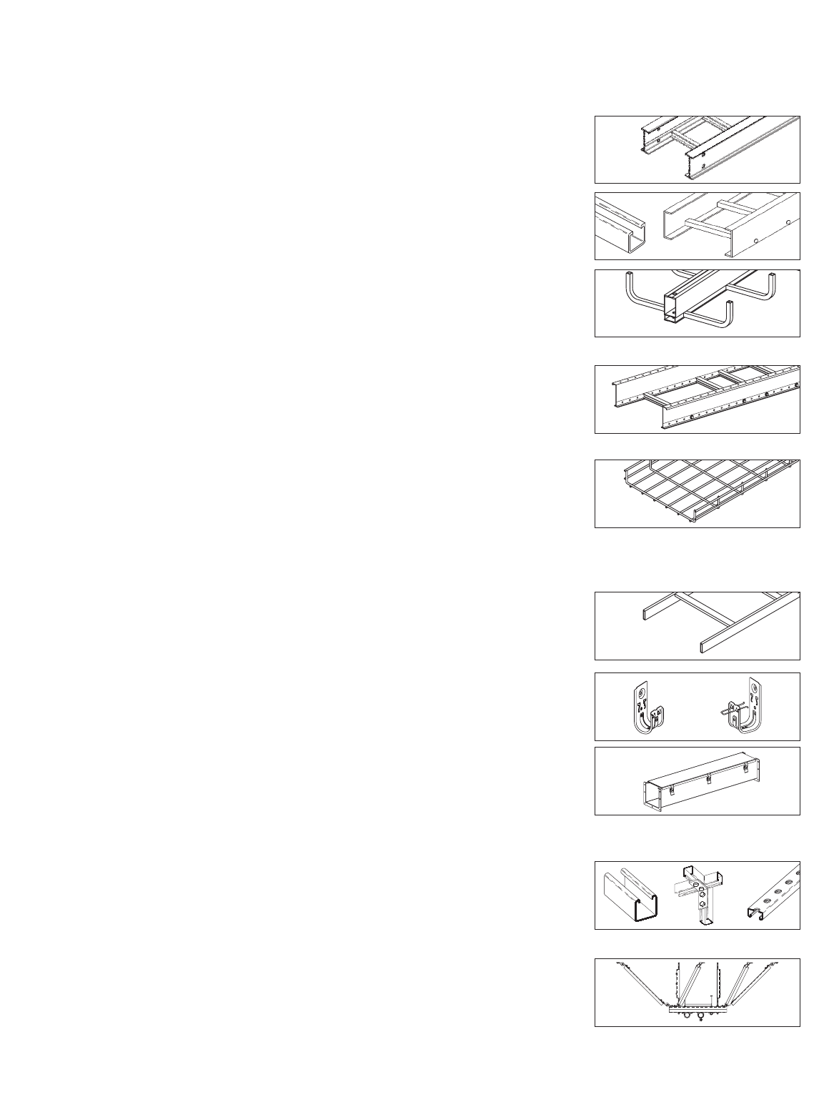
B-Line Wire Management Resources
B-Line Product Catalogs
• Cable Tray Systems (CT-02) . . . . . . . . . . . . . . . . . . . . . . . . . . . . .
Metallic, Two Siderail System
Commercial and Industrial Applications
• Fiberglass Cable Tray (CT01FRP) . . . . . . . . . . . . . . . . . . . . . . . .
Non-Metallic, Two Siderail Trays
Non-Metallic Strut Systems
• Cent-R-Rail®(CR-02) . . . . . . . . . . . . . . . . . . . . . . . . . . . . . . . . . . . .
Center Supported Cable Tray
“Lay-In” Cable Design for Easy Installation
of Low Voltage Cables
• Redi-Rail®(RR-01) . . . . . . . . . . . . . . . . . . . . . . . . . . . . . . . . . . . . . .
Pre-Punched Aluminum Side Rail Design
Unmatched Job Site Adaptability for a Two
Side Rail System - Load Depths 2” to 6”
• Wire Basket Runway (WB-02) . . . . . . . . . . . . . . . . . . . . . . . . . . .
Unmatched Adaptability to Site Conditions
Pre-Packaged Installation Kits and Accessories
Fast - Adaptable - Economical
Other B-Line Wire Management Systems
• Telecom (BLT-01) . . . . . . . . . . . . . . . . . . . . . . . . . . . . . . . . . . . . . . .
Saunders’ Cable Runway and Relay Racks
Unequal Flange Racks
• Cable Hooks (BLF-02) . . . . . . . . . . . . . . . . . . . . . . . . . . . . . . . . . . .
Supports all Cat 5, Fiber Optic, Innerduct
and Low Voltage Cabling Requirements
• Wireway (ENC-02) . . . . . . . . . . . . . . . . . . . . . . . . . . . . . . . . . . . . . .
Houses Runs of Control and Power Cable
Available in NEMA 12, Type 1 & Type 3R
B-Line Mechanical Support Systems
• Strut Systems (SS-00R) . . . . . . . . . . . . . . . . . . . . . . . . . . . . . . . . . .
Metal Framing Support System. Fully Adjustable
and Reusable, with a Complete Line of Channel,
Fittings and Accessories for Multi-Purpose Applications
• Seismic Restraints (SRS-02) . . . . . . . . . . . . . . . . . . . . . . . . . . . . .
Multi-Directional Bracing for Electrical Conduit,
Cable Tray and Mechanical Piping Systems.
OSHPD Pre-Approved Details
57
Cable Tray Manual Cooper B-Line, Inc
Cent-R-Rail
Redi-Rail
Wire Basket Metalic
Cable Tray
Non-Metalic
Cable Tray
Ask the Experts
Cooper B-Line, Inc
509 W. Monroe Street
Highland, IL 62249
Phone: 618-654-2184
Fax: 618-654-1917
101102 © 2002 Cooper B-Line
