Cooper Notification AMPRF-1 RF POWER AMPLIFIER WITH CERTIFIED TRANSCEIVER User Manual Standalone
Cooper Notification, Inc. RF POWER AMPLIFIER WITH CERTIFIED TRANSCEIVER Standalone
User Manual

Installation Instruction Sheet: AMP-RF-1
P/N P10-00071-A
1 of 7
INSTALLATION INSTRUCTIONS
Installation Instruction Sheet: AMP-RF-1
Instruction:
Model AMP-RF-1
Applicability:
Applies to WAVES CRLU and TRX Installs only
Part Number:
P10-00071
Date:
December 4, 2012
1. Purpose
This sheet provides the specifications of Indoor Amplifier model AMP-RF-1 along with detailed
instructions to install the 1 Watt, 2.4 GHz amplifier into a WAVES system using either a CRLU-201
or a TRX-401.
Model AMP-RF-1 is intended for indoor installations that require additional output power to
compensate for long transmission runs between the CRLU/TRX and the antenna.
2. Cautions and Warnings
The following are specific Cautions and Warnings that must be followed when installing or
operating equipment.
• Please read all instructions before attempting to install any equipment. Failure to
follow directions can cause bodily injury and/or damage to the equipment.
• Ensure that precautionary measures are employed to prevent applying power to
equipment at any time maintenance work is in progress.
• Do not make any unauthorized alterations to equipment or components. Changes or
modifications not expressly approved by Cooper Notification can result in damage
to the equipment and will void the warranty.
• When working near electricity do not use metal rules, flashlights, metallic pencils, or
any other object having exposed conducting material.
• Ensure all electrical connections are secure before applying power to a unit. Failure
to secure connections may cause an electrical arc resulting in physical shock or
damage to the equipment.
• Do not touch electronic components with wet hands.
• When possible, avoid installing equipment during severe or wet conditions.
Handling equipment with wet hands may cause slippage resulting in bodily injury
and/or damage to equipment.
• Comply with all electrical codes per the local authority having jurisdiction.
3. Tools
Required tools and equipment needed to install the amplifier shall be determined by qualified service
personnel.
Specifications
Installation Instruction Sheet: AMP-RF-1
P/N P10-00071 Rev A
INSTALLATION INSTRUCTIONS
2 of 3
4. Specifications
General Specifications of the AMP-RF-1 are listed below in Table 1.
Table 1 General Specifications
Spec RF Amplifier
Model AMP-RF-1
Transmit Power
Receive Gain
Frequency
Max Input Power
Min Input Power
Dimensions
Weight
Amplifier Current Draw
Amplifier Supply Voltage
Class II Power Supply Voltage Rating
Temperature
Input/Output Connectors
Compatible Access Points
1 Watt (30 dBm)
15 dB nominal
2.4 – 2.5 GHz
100 mW (20 dBm)
3 mW (5dBm)
4.5 x 2.5 x 1.3 in (117 x 64 x 33 mm)
.68 lbs (.30 Kg)
0.8 A @12VDC
9 - 12 VDC
110-240 VAC, 50/60 Hz
0 to 49 C (32 to 120 F) Indoor Use Only
N-Type Female
CRLU-201 and TRX-401 Series only
FCC WARNINGS
1. Modifications are not allowed to the amplifier or support equipment.
2. Any modification could void the User’s authority to operate the equipment.
3. Antenna placement must be no less than 1 meter from any potential point of
human contact or exposure.
4. The AMP-RF-1 amplifier can only be used with access point FCC ID:
X2PAMPRF-1. Access point FCC ID: X2PAMPRF-1 consists of one of the
antennas listed in this manual and an access point model CRLU-201 or TRX-
401. Refer to Section 7 Labeling Instructions, for special access point labeling
instructions.
AMP-RF-1 Outline Drawings
Installation Instruction Sheet: AMP-RF-1
P/N P10-00071 Rev A
INSTALLATION INSTRUCTIONS
3 of 3
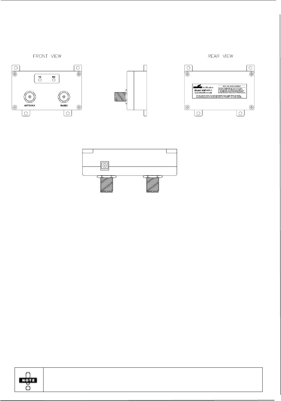
5. AMP-RF-1 Outline Drawings
Figures 1 and 2 below provide outline drawings of the Front, Side, Rear, and Top views of the
amplifier.
Figure 1 AMP-RF-1 Front/Side/Rear Views
Figure 2 AMP-RF-1 Top View/DC Power Connection
6. Installation
The installation of the power amplifier shall be conducted by qualified service personnel. To ensure
compliance with mandatory codes and standards all instructions listed in this document should be
followed.
For installations other than military applications, the use of the amplifier must meet EIRP (Effective
Isotropic Radiated Power) requirements mandated by the FCC. This section provides the basic
information required to define and calculate EIRP.
Each installation is unique therefore it is the responsibility of the service personnel to ensure proper
installation.
1. Calculate Transmission Line Loss including connector loss. Refer to section 6.1.1 for typical
loss when using LMR coax cable.
2. Identify the type of antenna in use. Refer to Table 3 for approved antenna types and their
respective gains.
3. Calculate the EIRP of the antenna being used. Refer to section 6.1.2 for EIRP formula.
4. If the calculated EIRP exceeds the FCC’s maximum EIRP rating, determine the additional
transmission line loss needed to adjust the EIRP to meet the FCC Rules. Refer to Table 4 for
EIRP values using the AMP-RF-1 amplifier.
Only antennas listed in this document are compatible with the AMP-RF-1 amplifier.
Installation
Installation Instruction Sheet: AMP-RF-1
P/N P10-00071 Rev A
INSTALLATION INSTRUCTIONS
4 of 3
6.1 Calculating Transmission Line Loss and EIRP
To calculate EIRP, the total transmission line loss between the amplifier and the antenna is required.
In some cases a minimum line loss is required to meet the FCC EIRP requirements. Refer to Table 4
for additional information to adjust EIRP.
6.1.1 Transmission Line Loss
Determining Transmission Line Loss requires knowledge of the cable type being used as well as the
type and quantity of connectors in the cable run between the amplifier and the antenna. Typical loss
values for LMR coax cable are listed below. However, the installer should calculate cable loss in
accordance with the appropriate cable and connectors being used.
Coax Cable Loss: LMR-240 has a 0.13 dB loss per foot
LMR-400 has a 0.07 dB loss per foot
LMR-600 has a 0.04 dB loss per foot
Connector loss: Approximately0.22 dB per connector
(Refer to specific connector type for actual loss)
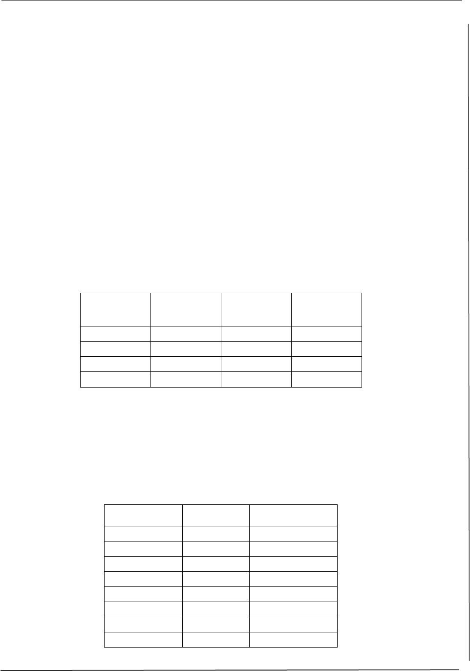
Table 2 identifies the calculated line loss for LMR-240, 400, and 600 for various cable lengths.
Table 2 Cable Loss for Specific Cable Lengths
Cable Length
(ft)
Typical Cable
loss (dB) for
LMR-240
Typical Cable
loss (dB) for
LMR-400
Typical Cable
loss (dB) for
LMR-600
25'
3
2
1
50'
7
4
2
100'
13
7
4
200'
26
14
8
6.1.2 EIRP Calculation
The formula for calculating EIRP is as follows:
EIRP (dBm) = amplifier output power (dBm) – transmission line loss (dB) + antenna gain (dBi)
Refer to Table 3 below for amplifier output power and antenna gain of approved antennas.
Table 3 Approved Antennas
Antenna Model
Antenna Gain
(dBi)
Amplifier Output
(dBm)
ANT-109-DR
9
30
ANT-115-DR
15
30
ANT-114-YAGI
13.9
30
ANT-115-YAGI
14.5
30
ANT-103-OM
3
30
ANT-106-0M
6
30
ANT-109-OM
9
30
ANT-115-OM
15
30
Installation
Installation Instruction Sheet: AMP-RF-1
P/N P10-00071 Rev A
INSTALLATION INSTRUCTIONS
5 of 3
6.1.3 Maximum and Adjusted EIRP
Table 4 below identifies compatible antennas, antenna gain, maximum EIRP and required
transmission line loss (as applicable).
When determining cable lengths to meet transmission line loss between the amplifier and the
antenna, if the cable distance is exceedingly long and does not provide adequate attenuation, it is
acceptable to add fixed 50 ohm external attenuators to ensure the required EIRP is met.
Table 4 Maximum and Adjusted EIRP
Antenna Model
Antenna
Gain
(dBi)
Amplifier
Output
(dBm)
EIRP
with no
line loss
(dBm)
Max EIRP
per
FCC Rules
(dBm)
Minimum Loss
required between
amplifier and antenna*
(dB)
Required
Adjusted
EIRP
(dBm)
ANT-109-DR
8
30
38
38
5* 33
ANT-115-DR
15.5
30
45.5
42
5* 40.5
ANT-114-YAGI
13.9
30
43.9
42
5* 38.9
ANT-115-YAGI
14.5
30
44.5
42
5* 39.5
ANT-103-OM
3
30
33
36
0 33
ANT-106-0M
6
30
36
36
0 36
ANT-109-OM
9
30
39
36
3 36
ANT-115-OM
15
30
45
36
9 36
*Indicates adjusted line loss to meet FCC EIRP exemption rules and harmonic limits
6.1.4 Line Loss between CRLU/TRX and Amplifier
Transmission line loss between the CRLU/TRX and the amplifier is also critical; the minimum
amplifier input power should be no less than 5 dBm and should be adjusted accordingly.
Amp input power (dBm) = CRLU/TRX output power (dBm) – Transmission Line Loss (dB)
CRLU/TRX Output Power = 20 dBm
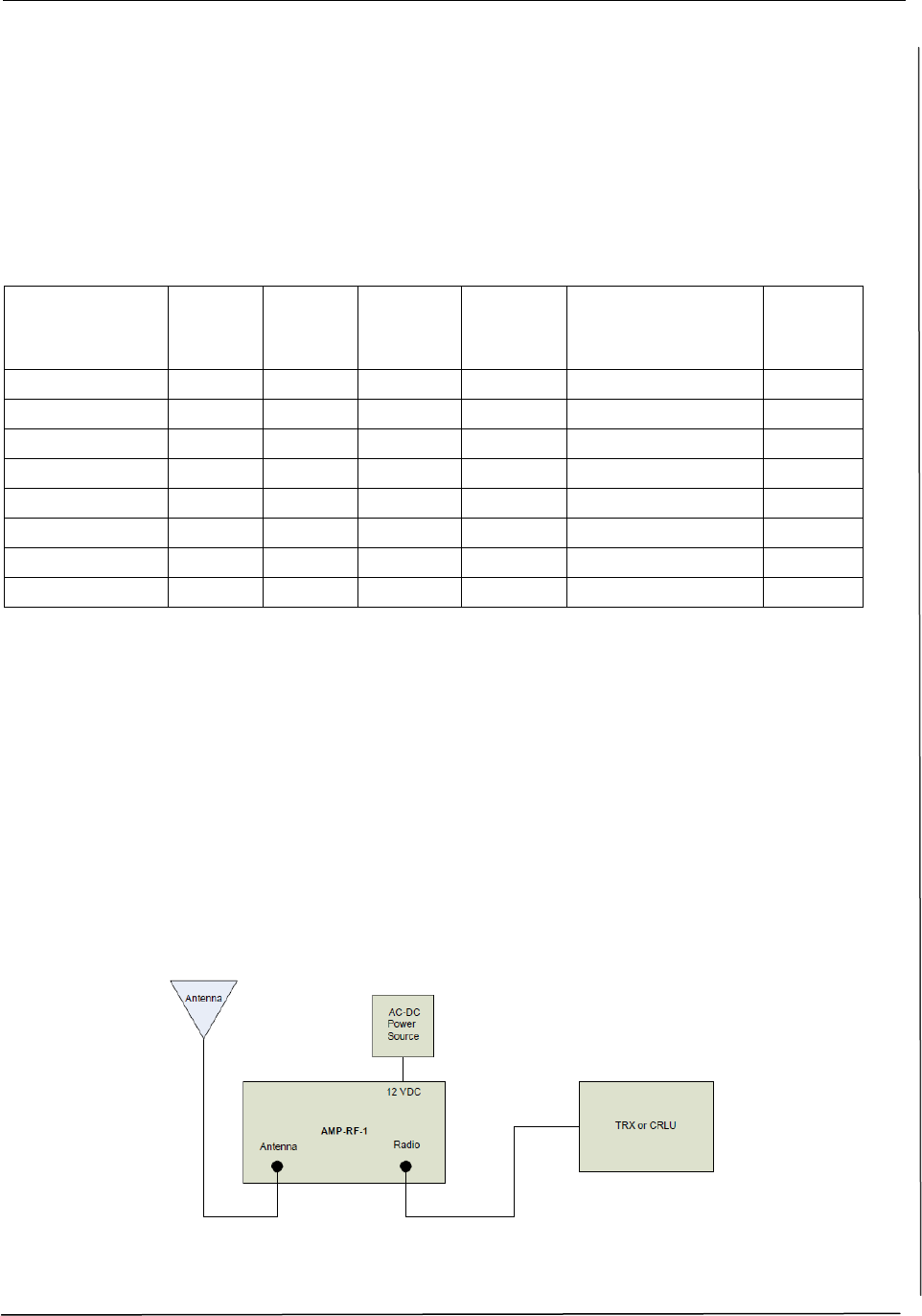
6.2 Wiring the Amplifier
Refer to the Amplifier Connection Diagram, Figure 3 below, while completing the installation steps.
Figure 3 Amplifier Connection Diagram
*Use only the Class II 12 VDC Power Supply provided with the amplifier
Labeling Instructions
Installation Instruction Sheet: AMP-RF-1
P/N P10-00071 Rev A
INSTALLATION INSTRUCTIONS
6 of 3
6.2.1 Amplifier Location
1. For security measures, it is recommended however not required, to mount the amplifier
in an enclosure.
2. The location of the amplifier is to be determined by qualified service personnel only. As
mentioned previously, input/output power, line loss, and antenna gain should all be
considered when identifying a location.
3. The amplifier supply must be powered from a 110 – 240 VAC, 50 – 60 Hz 15A power
source using the provided Class II power supply.
Provisions should be considered to provide backup power to the amplifier in case of power
failure.
6.2.2 Wiring from the CRLU/TRX to the Amplifier
1. Connect one end of the LMR coax cable to the N-Connector located on the top panel of
the CRLU/TRX.
2. Connect the other end of the LMR cable to the amplifier using the N connector on the
amplifier labeled Radio.
6.2.3 Wiring from the Amplifier to the Antenna
1. Connect one end of the LMR coax cable to the amplifier using the N connector on the
amplifier labeled Antenna.
2. Connect the other end of the LMR cable to the input of the antenna.
6.2.4 Powering the Amplifier
Input power to the amplifier is 12 VDC; DO NOT power the amplifier from the +15
VDC source on the CRLU/TRX; this may damage the equipment and void the
warranty.
1. Plug the amplifier’s power supply into an AC outlet. Plug the other end of the power
cable into the DC Power connection located at the top of the amplifier as indicated in
Figures 2 and 3.
2. If a signal is present at the amplifier, the TX and RX LEDs on the front of the amplifier
will be lit accordingly.
It is recommended that the amplifier and related equipment be provided with a Back-Up
power source to ensure operations are not disrupted when AC Power is lost.
7. Labeling Instructions
The FCC ID: X2PAMPRF-1 label included with the amplifier must be installed on the amplifier’s
CRLU-201 or TRX-401 access point. The placement of this label must cover the existing FCC ID
label on the front cover of the access point.
Revisions
Installation Instruction Sheet: AMP-RF-1
P/N P10-00071 Rev A
INSTALLATION INSTRUCTIONS
7 of 3
8. Revisions
Rev. ECN # Date Modification
A N/A Original
This equipment has been tested and found to comply with the limits for a Class A digital
device pursuant to part 15 of the FCC Rules. These limits are designed to provide
reasonable protection against harmful interference when the equipment is operated in a
commercial environment. This equipment generates, uses, and can radiate radio frequency
energy and, if not installed and used in accordance with the instruction manual, may cause
harmful interference to radio communications. Operation of this equipment in a residential
area is likely to cause harmful interference in which case the user will be required to correct
the interference at his/her own expense.